1
Test Report issued under the responsibility of:
NVLAP Lab Code 100426-0
This report must not be used to claim product certification,
approval, or endorsement by NVLAP, NIST, or any agency of
the Federal Government. Nemko USA, Inc. is a NVLAP
www.nemko.com
accredited laboratory.
TEST REPORT
FCC Part 15
ICES-003
Radio Frequency Devices
Subpart B – Unintentional Radiators
Digital Apparatus
Report Reference No. ..................... : 10240453EUS1
Compiled by (+ signature) ............... : Brian Boyea
Approved by (+ signature) ................ : Mike Cantwell
Date of issue ................................... : 14-Jun-13
Report Revision ............................... : 3
Total number of pages .................... : 24
Testing Laboratory ......................... : Nemko USA, Inc. (Dallas)
Address ........................................... : 802 N. Kealy Ave.
Lewisville, TX 75057
USA
Tel: +1 972 436 9600
Fax: +1 972 436 2667
Applicant’s name ............................ : Texas Instruments, Inc.
Address ............................................. : 12500 TI BLVD, Dallas, TX 75243
Model(s) Tested............................... : GASSENSOREVM
Test specification:
Standard ........................................... : FCC Part 15, Subpart B & ICES-003, Issue 4 (Feb-2004)
Test procedure .................................. : CCA
Non-standard test method ................ : N/A
TRF Revision .................................... : 11-Feb-13
Nemko USA, Inc. 802 N. Kealy Ave. Lewisville, TX
Tel: +1 972-436-9600 Fax: +1 972-436-9600
USA
Page 1 of 24
FCC Part 15, Subpart B & ICES-003, Issue 4 (Feb-2004)
Report Number: 10240453EUS1
Revision: 3
Issue Date: 14-Jun-13
Revision History
#
Description
Date
0
Original Report Release
15-Apr-13
1
Checked Class B compliance box on page 9
11-May-13
2
Changed model to GasSensorEVM
14-Jun-13
3
Changed model to GASSENSOREVM
14-Jun-13
Notices:
1. This report shall not be reproduced, except in full, without the written approval of the Issuing testing
laboratory.
2. The test results presented in this report relate only to the object tested.
3. The results contained in this report reflect the results for this particular model and serial number. It is the
responsibility of the manufacturer to ensure that all production models meet the intent of the requirements
detailed within this report.
4. "(see Enclosure #)" refers to additional information appended to the report.
5. Throughout this report a point is used as the decimal separator.
6. Dimensions in English units for convenience only, metric units prevail.
Responsible Party:
In accordance with 47 CFR 2.995(x), record retention under verification authorization procedure, or 47 CFR
2.1075(x), record retention under declaration of conformity authorization procedure, the name and signature of
an official of the responsible party, as designated in 47 CFR 2.909 shall appear on the report. The following
signature block is provided for this purpose.
Signature:
Name:
Nemko USA, Inc. 802 N. Kealy Ave. Lewisville, TX
Tel: +1 972-436-9600 Fax: +1 972-436-9600
USA
Page 2 of 24
FCC Part 15, Subpart B & ICES-003, Issue 4 (Feb-2004)
Report Number: 10240453EUS1
Revision: 3
Issue Date: 14-Jun-13
Table of Contents
Revision History ................................................................................................................................................................. 2
Normative References ........................................................................................................................................................ 4
Equipment Under Test (EUT) ............................................................................................................................................. 5
Details: ........................................................................................................................................................................... 5
EUT Configuration ......................................................................................................................................................... 6
EUT Photo(s) ................................................................................................................................................................. 8
Summary of Testing ............................................................................................................................................................ 9
Testing Location ........................................................................................................................................................... 10
Procedural Requirements ............................................................................................................................................ 10
United States ........................................................................................................................................................... 10
Canada .................................................................................................................................................................... 10
Information to the User and Labeling Requirements ................................................................................................... 10
United States ........................................................................................................................................................... 11
Canada .................................................................................................................................................................... 13
Technical Requirements ................................................................................................................................................... 13
Radiated Emissions .......................................................................................................................................................... 13
30 MHz to 1 GHz ..................................................................................................................................................... 14
Above 1 GHz ........................................................................................................................................................... 14
Conducted Emissions ....................................................................................................................................................... 15
Mains............................................................................................................................................................................ 15
Measurement Uncertainty ................................................................................................................................................ 16
List of Test Equipment ...................................................................................................................................................... 16
Test Results – Radiated Emissions (below 1 GHz) .......................................................................................................... 17
Test Results – Radiated Emissions (above 1 GHz) ......................................................................................................... 20
Setup Photos .................................................................................................................................................................... 23
Nemko USA, Inc. 802 N. Kealy Ave. Lewisville, TX
Tel: +1 972-436-9600 Fax: +1 972-436-9600
USA
Page 3 of 24
FCC Part 15, Subpart B & ICES-003, Issue 4 (Feb-2004)
Report Number: 10240453EUS1
Revision: 3
Issue Date: 14-Jun-13
Normative References
The following document(s) have been appropriately considered in the performance of the test results
detailed in this report.
Code of Federal Regulations – Title 47 – Telecommunications, Part 15 – Radio Frequency
Devices
ANSI C63.4:2003
Methods of Measurement of Radio-Noise Emissions from Low-Voltage Electrical and Electronic
Equipment in the Range of 9 kHz to 40 GHz
ANSI C63.4:2009 [informative only]
Methods of Measurement of Radio-Noise Emissions from Low-Voltage Electrical and Electronic
Equipment in the Range of 9 kHz to 40 GHz [KDB No. 704992 dated 10-Mar-2010]
CISPR-22:2003
Information Technology Equipment—Radio Disturbance Characteristics—Limits and Methods
of Measurement [47 CFR 15.31(a)(3) excludes clauses 4.1.5.2, 5.7, 9, & 14 and specifies test
method as ANSI C63.4] [ICES-003, clause 5, Limits, does not include conducted emissions on
telecommunications ports]
ICES-003 (Issue 4, Feb-2004)
Digital Apparatus
CAN/CSA-CEI/IEC CISPR 22:02
Limits and Methods of Measurement of Radio Disturbance Characteristics of Information
Technology Equipment
Nemko USA, Inc. 802 N. Kealy Ave. Lewisville, TX
Tel: +1 972-436-9600 Fax: +1 972-436-9600
USA
Page 4 of 24
FCC Part 15, Subpart B & ICES-003, Issue 4 (Feb-2004)
Report Number: 10240453EUS1
Revision: 3
Issue Date: 14-Jun-13
Equipment Under Test (EUT)
Details:
Test item description:
Model ............................................... : GASSENSOREVM
Serial Number ................................. : SAT0009_SAT0010
Production Status ............................ :
Production
Pre-Production
Prototype
Other Status Info ................ : Consists of SAT0009 &SAT0010
EUT Received Date ........................ : 8-Apr-13
Ratings ............................................ : 3VDC
1φ
3φ
General product description:
TI Gas Sensor Demo Platform with BLE
Modifications to the EUT required for compliance:
There have been no modifications to the EUT as a result of this evaluation.
Deviations from Test Methodology:
There have been no deviations, additions to, or exclusions from the specified test standard.
Engineering Judgements:
No engineering judgments based on the results in this test report have been made.
Approved by (+ signature) ................ :
Nemko USA, Inc. 802 N. Kealy Ave. Lewisville, TX
Tel: +1 972-436-9600 Fax: +1 972-436-9600
Click here to enter text.
USA
Page 5 of 24
FCC Part 15, Subpart B & ICES-003, Issue 4 (Feb-2004)
Report Number: 10240453EUS1
Revision: 3
Issue Date: 14-Jun-13
Table 1 – EUT Internal Operating Frequencies
Frequency (MHz)
Description
2402-2478MHz
Transmit
Frequency (MHz)
Description
Table 2 – EUT Operating Modes
Mode #
1
Description
Powered on
2
3
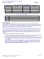
EUT Configuration
A minimum representative configuration, as defined by the manufacturer, has been used for the testing
performed herein. The selection of hardware (including interface ports), software, and cables were chosen by the
manufacturer as being representative of the product’s intended use. The interconnection of various articles of
equipment and the types of cables used has also been defined by the manufacturer.
The placement of the equipment under test has been, to the extent practical, arranged to maximize emissions.
Cables, of the type and length specified by the manufacturer, were connected to at least one of each type of
interface port provided by the EUT and if practical, were terminated by a device typical of actual usage. For
multiple ports of the same type, the addition of cables did not significantly affect the emission level (i.e. < 2B
variation).
The arrangement of external power supply units was as follows:
a) If the mains input cable of the external power supply unit is greater than 0,8 m, the external power supply
unit shall be placed on the tabletop, with a nominal 0,1 m separation from the host unit.
b) If the external power supply unit has a mains input cable that is less than 0,8 m, the external power supply
unit shall be placed at a height above the ground plane such that its power cable is fully extended in the
vertical direction.
c) If the external power supply unit is incorporated into the mains power plug, it shall be placed on the
tabletop. An extension cable shall be used between the external power supply unit and the source of
power . The extension cable should be connected in a manner such that it takes the most direct path
between the external power supply unit and the source of power.
Nemko USA, Inc. 802 N. Kealy Ave. Lewisville, TX
Tel: +1 972-436-9600 Fax: +1 972-436-9600
USA
Page 6 of 24
FCC Part 15, Subpart B & ICES-003, Issue 4 (Feb-2004)
Report Number: 10240453EUS1
Revision: 3
Issue Date: 14-Jun-13
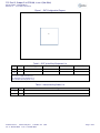
Figure 1 - EUT Configuration Diagram
A
Table 3 – EUT & Auxilliary Equipment List
Item
A
Use*
Product Type
Manufacturer
Model
Serial No.
EUT
TI Gas Sensor
TI
GASSENSOREVM
None
B
Note:
* Use = EUT - Equipment Under Test,
AE - Auxiliary/Associated Equipment, or
SIM - Simulator (Not Subjected to Test)
Table 4 - Interconnecting Cables List
Item
Use*
Cable Type
1
2
Nemko USA, Inc. 802 N. Kealy Ave. Lewisville, TX
Tel: +1 972-436-9600 Fax: +1 972-436-9600
USA
Page 7 of 24
FCC Part 15, Subpart B & ICES-003, Issue 4 (Feb-2004)
Report Number: 10240453EUS1
Revision: 3
Issue Date: 14-Jun-13
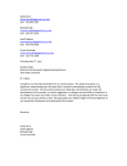
EUT Photo(s)
Photo 1
EUT Photo – Front/Top View
Supplemental Information:
Nemko USA, Inc. 802 N. Kealy Ave. Lewisville, TX
Tel: +1 972-436-9600 Fax: +1 972-436-9600
USA
Page 8 of 24
FCC Part 15, Subpart B & ICES-003, Issue 4 (Feb-2004)
Report Number: 10240453EUS1
Revision: 3
Issue Date: 14-Jun-13
Summary of Testing
Possible test case verdicts:
- test case does not apply to the test object : N/A
- test object does meet the requirement ...... : P (Pass)
- test object does not meet the requirement : F (Fail)
- not tested (not part of this evaluation) ....... : NT
Date(s) of performance of tests ................... : 8-April-2013
Class ............................................................ :
Clause
A
B
Test Description
Verdict
Comment
47 CFR
15.107
Conducted Emissions - Mains
N/A
15.109
Radiated Emissions
Using CISPR-22 Limit per 15.109(g)
Using FCC Limits per 15.109(a) or 15.109(b)
Note 1
P
ICES-003
5.2 or 5.3
Conducted Emissions - Mains
5.4 or 5.5
Radiated Emissions
N/A
Note 1
P
Notes:
Note 1: The EUT is battery powered.
General remarks:
Summary of compliance with national requirements:
Compliance with this standard provides a means of conformity with the United States Federal
Communication Commission (FCC) verification, certification, or declaration of conformity authorization
procedures and Industry Canada (IC) rules.
Nemko USA, Inc. 802 N. Kealy Ave. Lewisville, TX
Tel: +1 972-436-9600 Fax: +1 972-436-9600
USA
Page 9 of 24
FCC Part 15, Subpart B & ICES-003, Issue 4 (Feb-2004)
Report Number: 10240453EUS1
Revision: 3
Issue Date: 14-Jun-13
Testing Location
Testing Laboratory:
Nemko USA, Inc. (Dallas)
Testing location/ address .......................... : 802 N. Kealy Ave.
Lewisville, TX 75057
USA
Testing procedure: TMP
Tested by (name + signature)
:
Approved by (+ signature)
:
Testing location/ address ......................... :
Supplemental Information:
Testing results contained herein were performed at the location(s) listed above.
Procedural Requirements
The following requirements are taken from the appropriate rules, other rules may apply and the manufacturer
should consult the full text of the appropriate laws prior to marketing any device.
United States
Mandated procedures for digital devices are defined in 47 CFR 15.101, Equipment authorization of unintentional
radiators. Details of the authorization procedures (verification, declaration of conformity, and certification) can be
found in 47 CFR, Part 2, Subpart J, Equipment Authorization Procedures.
Canada
Clause 6 of ICES-003 contains the procedural requirements.
6.1: A record of the measurements and results, showing the date that the measurements were completed, shall
be retained by the manufacturer or importer for a period of at least five years from the date shown in the record
and made available for examination on the request of the Minister.
6.2: A written notice indicating compliance must accompany each unit of digital apparatus to the end user. The
notice shall be in the form of a label that is affixed to the apparatus. Where because of insufficient space or other
constraints it is not feasible to affix a label to the apparatus, the notice may be in the form of a statement included
in the user's manual. A suggested text for the notice, in English and in French, is provided in the Annex.
Information to the User and Labeling Requirements
The following requirements are taken from the appropriate rules, other rules may apply and the manufacturer
should consult the full text of the appropriate laws prior to marketing any device.
Nemko USA, Inc. 802 N. Kealy Ave. Lewisville, TX
Tel: +1 972-436-9600 Fax: +1 972-436-9600
USA
Page 10 of 24
FCC Part 15, Subpart B & ICES-003, Issue 4 (Feb-2004)
Report Number: 10240453EUS1
Revision: 3
Issue Date: 14-Jun-13
United States
47 CFR 15.19(a)(1): Receivers associated with the operation of a licensed radio service shall bear the following
statement in a conspicuous location on the device:
This device complies with part 15 of the FCC Rules. Operation is subject to the condition
that this device does not cause harmful interference.
47 CFR 15.19(a)(2): A stand-alone cable input selector switch, shall bear the following statement in a
conspicuous location on the device:
This device is verified to comply with part 15 of the FCC Rules for use with cable
television service.
47 CFR 15.19(a)(3): All other devices shall bear the following statement in a conspicuous location on the device:
This device complies with part 15 of the FCC Rules. Operation is subject to the following
two conditions: (1) This device may not cause harmful interference, and (2) this device
must accept any interference received, including interference that may cause undesired
operation.
47 CFR 15.19(a)(5): When the device is so small or for such use that it is not practicable to place the statement
specified under paragraph (a) of this section on it, the information required by this paragraph shall be placed in a
prominent location in the instruction manual or pamphlet supplied to the user or, alternatively, shall be placed on
the container in which the device is marketed. However, the FCC identifier or the unique identifier, as
appropriate, must be displayed on the device.
Nemko USA, Inc. 802 N. Kealy Ave. Lewisville, TX
Tel: +1 972-436-9600 Fax: +1 972-436-9600
USA
Page 11 of 24
FCC Part 15, Subpart B & ICES-003, Issue 4 (Feb-2004)
Report Number: 10240453EUS1
Revision: 3
Issue Date: 14-Jun-13
47 CFR 15.19(b): Products subject to authorization under a Declaration of Conformity shall be labeled as follows:
47 CFR 15.19(b)(1): The label shall be located in a conspicuous location on the device and shall contain the
unique identification described in 47 CFR 2.1074 (Devices subject only to a Declaration of Conformity shall be
uniquely identified by the responsible party. This identification shall not be of a format which could be confused
with the FCC Identifier required on certified, notified, type accepted or type approved equipment. The
responsible party shall maintain adequate identification records to facilitate positive identification for each device.)
of this chapter and [one of] the following logo[s]:
(i) If the product is authorized based on testing of
the product or system; or
(ii) If a personal computer is authorized based on
assembly using separately authorized
components, in accordance with §15.101(c)(2) or
(c)(3), and the resulting product is not separately
tested:
47 CFR 15.19(b)(2) Label text and information should be in a size of type large enough to be readily legible,
consistent with the dimensions of the equipment and the label. However, the type size for the text is not required
to be larger than eight point.
47 CFR 15.19(b)(3): When the device is so small or for such use that it is not practicable to place the statement
specified under paragraph (b)(1) of this section on it, such as for a CPU board or a plug-in circuit board peripheral
device, the text associated with the logo may be placed in a prominent location in the instruction manual or
pamphlet supplied to the user. However, the unique identification (trade name and model number) and the logo
must be displayed on the device.
47 CFR 15.19(b)(4): The label shall not be a stick-on, paper label. The label on these products shall be
permanently affixed to the product and shall be readily visible to the purchaser at the time of purchase, as
described in §2.925(d) of this chapter. “Permanently affixed” means that the label is etched, engraved, stamped,
silkscreened, indelibly printed, or otherwise permanently marked on a permanently attached part of the
equipment or on a nameplate of metal, plastic, or other material fastened to the equipment by welding, riveting,
or a permanent adhesive. The label must be designed to last the expected lifetime of the equipment in the
environment in which the equipment may be operated and must not be readily detachable.
47 CFR 15.21: The user’s manual or instruction manual for an intentional or unintentional radiator shall caution
the user that:
Changes or modifications not expressly approved by the party responsible for
compliance could void the user's authority to operate the equipment.
In cases where the manual is provided only in a form other than paper, such as on a computer disk or over the
Internet, the information required by this section may be included in the manual in that alternative form, provided
the user can reasonably be expected to have the capability to access information in that form.
47 CFR 15.105(a): For a Class A digital device or peripheral, the instructions furnished the user shall include the
following or similar statement, placed in a prominent location in the text of the manual:
Nemko USA, Inc. 802 N. Kealy Ave. Lewisville, TX
Tel: +1 972-436-9600 Fax: +1 972-436-9600
USA
Page 12 of 24
FCC Part 15, Subpart B & ICES-003, Issue 4 (Feb-2004)
Report Number: 10240453EUS1
Revision: 3
Issue Date: 14-Jun-13
Note: This equipment has been tested and found to comply with the limits for a Class A digital device,
pursuant to part 15 of the FCC Rules. These limits are designed to provide reasonable protection against
harmful interference when the equipment is operated in a commercial environment. This equipment
generates, uses, and can radiate radio frequency energy and, if not installed and used in accordance with
the instruction manual, may cause harmful interference to radio communications. Operation of this
equipment in a residential area is likely to cause harmful interference in which case the user will be
required to correct the interference at his own expense.
47 CFR 15.105(b): For a Class B digital device or peripheral, the instructions furnished the user shall include the
following or similar statement, placed in a prominent location in the text of the manual:
Note: This equipment has been tested and found to comply with the limits for a Class B digital device,
pursuant to part 15 of the FCC Rules. These limits are designed to provide reasonable protection against
harmful interference in a residential installation. This equipment generates, uses and can radiate radio
frequency energy and, if not installed and used in accordance with the instructions, may cause harmful
interference to radio communications. However, there is no guarantee that interference will not occur in a
particular installation. If this equipment does cause harmful interference to radio or television reception,
which can be determined by turning the equipment off and on, the user is encouraged to try to correct the
interference by one or more of the following measures:
—
—
—
—
Reorient or relocate the receiving antenna.
Increase the separation between the equipment and receiver.
Connect the equipment into an outlet on a circuit different from that to which the receiver is connected.
Consult the dealer or an experienced radio/TV technician for help.
Canada
ICES-003 suggests the following text for the notice indicating compliance:
This Class [*] digital apparatus complies with Canadian ICES-003.
Cet appareil numérique de la classe [*] est conforme à la norme NMB-003 du Canada.
Technical Requirements
The testing requirements, as appropriate, were derived from ANSI C63.4; 47 CFR, Subpart A; and CISPR-22.
Radiated Emissions
The arrangement of the equipment is typical of a normal installation practice and as was practical, the
arrangement was varied and emissions investigated for maximum amplitude. Final measurements were
performed in a semi-anechoic chamber or on an open area test site (OATS). The equipment was rotated 360°
and the antenna height has been varied between 1m and 4m. Measurements were taken at both horizontal and
vertical antenna polarities. The receiver bandwidth was set to 120 kHz for measurements below 1 GHz, and 1
Nemko USA, Inc. 802 N. Kealy Ave. Lewisville, TX
Tel: +1 972-436-9600 Fax: +1 972-436-9600
USA
Page 13 of 24
FCC Part 15, Subpart B & ICES-003, Issue 4 (Feb-2004)
Report Number: 10240453EUS1
Revision: 3
Issue Date: 14-Jun-13
MHz for measurements above 1 GHz. A peak detector is used to detect an emission; a quasi-peak detector may
be used to record a final measurement below 1 GHz and an average detector may be used above 1 GHz. An
inverse proportionality factor of 20 dB/decade (10 dB) was used, as noted in 15.31(f)(1), to normalize the
measured data to the specified test distance for determining compliance.
Table 5 – Highest Measurement Frequency
Highest EUT Clock
Highest Measurement
Below 1.705 MHz
30 MHz
1.705 MHz – 108 MHz
1 GHz
108 MHz – 500 MHz
2 GHz
500 MHz – 1 GHz
5 GHz
Above 1 GHz
5th harmonic of the highest
frequency or 40 GHz,
whichever is lower.
30 MHz to 1 GHz
Reading on the measuring receiver showing fluctuations close to the limit, were observed for at least 15 s at each
measurement frequency; the highest reading was recorded.
Table 6 – Radiated Emissions Limits per 47 CFR 15.109(a) & (b) (30 MHz to 1 GHz)
3m
2
10m
1
2
1
Frequency Range
Class A
(dBµV/m)
Class B
(dBµV/m)
Class A
(dBµV/m)
Class B
(dBµV/m)
30 MHz – 88 MHz
49.1
40.0
39.1
30.0
88 MHz – 216 MHz
53.5
43.5
43.5
33.5
216 MHz – 960 MHz
56.4
46.0
46.4
56.0
Note: The lower limit applies at the transition frequency.
1 Specified at a test distance of 3m
2 Specified at a test distance of 10m
Table 7 – Radiated Emissions Limits per 47 CFR 15.109(g) (30 MHz to 1 GHz)
3m
10m
Frequency Range
Class A
(dBµV/m)
Class B
(dBµV/m)
Class A
(dBµV/m)
Class B
(dBµV/m)
30 MHz – 230 MHz
50
40
40
30
230 MHz – 1 GHz
57
47
47
37
Note: The lower limit applies at the transition frequency.
Above 1 GHz
Table 8 - Radiated Emissions Limits per 47 CFR 15.109(a) & (b) @ 3m (1 GHz – 6 GHz)
Class A (dBµV/m)
Class B (dBµV/m)
Frequency Range
Average
Peak
Average
Peak
960 MHz – 40 GHz
60.0
80.0
54
74
Nemko USA, Inc. 802 N. Kealy Ave. Lewisville, TX
Tel: +1 972-436-9600 Fax: +1 972-436-9600
USA
Page 14 of 24
FCC Part 15, Subpart B & ICES-003, Issue 4 (Feb-2004)
Report Number: 10240453EUS1
Revision: 3
Issue Date: 14-Jun-13
Table 9 - Radiated Emissions Limits per 47 CFR 15.109(g) @ 3m (1 GHz – 6 GHz)
Class A (dBµV/m)
Class B (dBµV/m)
Frequency Range
Average
Peak
Average
Peak
1 GHz – 3 GHz
56
76
50
70
3 GHz – 6 GHz
60
80
54
74
Conducted Emissions
The mains cable of the EUT or EUT host unit was connected to the LISN defined in this standard and is bonded
to the reference plane. Where applicable, remaining auxiliary equipment was powered through an additional
LISN (also bonded to the reference plane), using a multi-socket outlet strip if necessary. The LISNs were at least
0.8m away from the EUT. A vertical ground plane was used while the table-top EUTs were placed on a wooden
table 0.8m high. Floor-standing EUTs were insulated from the ground plane and grounded according to the
manufacturer’s instructions.
Signal cables were positioned for their entire lengths, as far as possible, at a nominal distance of 0.4 m from the
ground reference plane. Where the mains cable supplied by the manufacturer was longer than 1 m, the excess
was folded at the centre into a bundle no longer than 0.4 m, so that its length is shortened to 1 m. If the 1 m cable
length cannot be achieved owing to physical limitations of the EUT arrangement, the cable length shall be as
near to 1 m as possible.
All telecommunication and signal ports were correctly terminated using either appropriate associated equipment
or a representative termination during the measurement of the conducted disturbances at the mains. If an ISN is
connected to a telecommunications port during the measurement of conducted disturbances at the mains port,
then the ISN receiver port was terminated in 50Ω. The ISNs were at least 0.8m away from the EUT.
Mains
Any power cable(s) from the equipment under test that were directly connected to the AC Mains have been
tested. In the event that the equipment under test had no direct connection to the Mains, that is, it was connected
to a Host unit (example: USB powered); then conducted emissions was performed on the Mains of the Host unit.
Battery powered equipment was not tested for conducted emissions; however, if the equipment makes
provisions for connections to a battery charger that is connected to the Mains, then conducted emissions were
performed on the battery charger.
Table 10 – Class A Conducted Emissions Limits - Mains
Limits (dBµV)
Frequency
Quasi-peak
Average
150 kHz – 500 kHz
79
66
500 kHz – 30 MHz
73
60
NOTE: The lower limit shall apply at the transition frequency.
Nemko USA, Inc. 802 N. Kealy Ave. Lewisville, TX
Tel: +1 972-436-9600 Fax: +1 972-436-9600
USA
Page 15 of 24
FCC Part 15, Subpart B & ICES-003, Issue 4 (Feb-2004)
Report Number: 10240453EUS1
Revision: 3
Issue Date: 14-Jun-13
Table 11 – Class B Conducted Emissions Limits - Mains
Limits (dBµV)
Frequency
Quasi-peak
Average
150 kHz – 500 kHz
66 - 56
56-46
500 kHz – 5 MHz
56
46
5 MHz – 30 MHz
60
50
NOTE 1: The lower limit shall apply at the transition frequency.
NOTE 2: The limit decreases linearly with the logarithm of the
frequency in the range 150 kHz to 500 kHz.
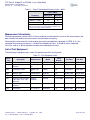
Measurement Uncertainty
Determining compliance with the limits in these standards was based on the results of the measurement, and
does not take into account the measurement instrumentation uncertainty.
Referencing the measurement instrumentation uncertainty considerations contained in CISPR 16-4-2, the
expanded measurement uncertainty is ±4.90 dB for radiated emissions, ±3.46 dB for mains conducted
emissions, and ±4.31 dB for telecommunication ports conducted emissions.
List of Test Equipment
The following test equipment was used in the performance of the testing herein.
Table 12 – Test Equipment Used
Asset
Tag
Description
Manufacturer
Serial
Number
Model
Cal. Date
Cal. Due
1942
Weather Station
Omega
wTHBP-LCD
none
25-Apr-2012
25-Apr-2013
1
3m Semi-Anechoic
Chamber
Nemko USA,
Inc.
Chamber
1
25-Sep-2012
25-Sep-2013
1025
Preamplifier, 25dB
Nemko USA,
Inc.
LNA25
399
5-Mar-2013
5-Mar-2014
1304
Antenna, Horn
Electro Metrics
RGA-60
6151
24-Nov-2011
24-Nov-2014
1763
Antenna, Bilog
Schaffner
CBL 6111D
22926
07-Mar-2013
07-Mar-2014
1767
Receiver, EMI Test 20Hz
- 26.5 GHz - 150 - +30
dBm LCD
Rohde &
Schwartz
ESIB26
837491/0002
19-Dec-2012
19-Dec-2013
1783
Cable Assy, 3m
Chamber
Nemko
Chamber
26-Sep-2012
26-Sep-2013
1785
Preamplifier
A.H. Systems
PAM-0126
09-Jan-2013
09-Jan-2014
Nemko USA, Inc. 802 N. Kealy Ave. Lewisville, TX
Tel: +1 972-436-9600 Fax: +1 972-436-9600
USA
143
Page 16 of 24
FCC Part 15, Subpart B & ICES-003, Issue 4 (Feb-2004)
Report Number: 10240453EUS1
Revision: 3
Issue Date: 14-Jun-13
Test Results – Radiated Emissions (below 1 GHz)
Nemko USA, Inc. 802 N. Kealy Ave. Lewisville, TX
Tel: +1 972-436-9600 Fax: +1 972-436-9600
USA
Page 17 of 24
FCC Part 15, Subpart B & ICES-003, Issue 4 (Feb-2004)
Report Number: 10240453EUS1
Revision: 3
Issue Date: 14-Jun-13
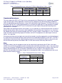
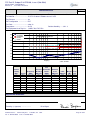
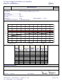
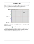
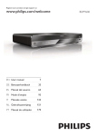
Table No. 1
Verdict
Radiated Emissions
Frequency Range ................... : 30 MHz to 1 GHz
P
Test Location ........... : 3m Chamber
Test Method .............................. : 47 CFR 15.109 & ICES-003 clauses 5.4/5.5
Test Distance .......................... : 3m
EUT Configuration .................. : EUT
Test Date ................................ : 8-Apr-13
Temperature ........................... : 23.3°C
Relative Humidity .... : 62.1 %
Test Equipment Asset Tag List : 1,1025,1763,1767,1783
100.0
Peak emission
90.0
Class A EN55022
Radiated Emissions - Horiz ontal
Class B EN55022
Amplitude(dBuV/m@3m)
80.0
70.0
Class A FCC
Class B FCC
60.0
50.0
40.0
30.0
20.0
10.0
0
10M
100M
1G
Frequency
Job No.: 10240453
(1)
(2)
Antenna
Polarity
(H/V)
Detector
H
QPK
H
QPK
H
H
H
H
H
H
H
H
(3)
(6)
Frequency
(MHz)
104.0150
972.3080
Receiver
Reading
(dBµV/m)
32.1
18.0
(7)
Site
Correction
Factor
(dB/m)
-15.4
1.3
(8)
(9)
Emission
Level
(dBµV/m)
16.7
19.2
Limit
(dBµV/m)
40.0
47.0
(10)
(11)
Margin Pass/
(dB)
Fail
23.3
Pass
27.8
Pass
Supplemental Information:
Tested by (+ signature) .....................:
Nemko USA, Inc. 802 N. Kealy Ave. Lewisville, TX
Tel: +1 972-436-9600 Fax: +1 972-436-9600
Brian Boyea
USA
Page 18 of 24
FCC Part 15, Subpart B & ICES-003, Issue 4 (Feb-2004)
Report Number: 10240453EUS1
Revision: 3
Issue Date: 14-Jun-13
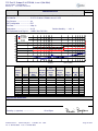
Table No. 2
Verdict
Radiated Emissions
Frequency Range ................... : 30 MHz to 1 GHz
P
Test Location ........... : 3m Chamber
Test Method .............................. : 47 CFR 15.109 & ICES-003 clauses 5.4/5.5
Test Distance .......................... : 3m
EUT Configuration .................. : EUT
Test Date ................................ : 8-Apr-13
Temperature ........................... : 23.3°C
Relative Humidity .... : 62.1 %
Test Equipment Asset Tag List : 1,1025,1763,1767,1783
100.0
Peak emission
90.0
Class A EN55022
Radiated Emissions - Vertical
Class B EN55022
Amplitude(dBuV/m@3m)
80.0
Class A FCC
Class B FCC
70.0
60.0
50.0
40.0
30.0
20.0
10.0
0
10M
100M
1G
Frequency
Job No.: 10240453
(1)
(2)
Antenna
Polarity
(H/V)
Detector
V
QPK
V
QPK
V
QPK
V
QPK
V
V
V
V
V
V
(3)
(6)
Frequency
(MHz)
30.8359
96.0298
112.0280
720.0120
Receiver
Reading
(dBµV/m)
17.3
38.8
39.7
33.2
(7)
Site
Correction
Factor
(dB/m)
-9.0
-16.4
-14.6
-2.8
(8)
(9)
Emission
Level
(dBµV/m)
8.3
22.4
25.1
30.4
Limit
(dBµV/m)
40.0
40.0
40.0
47.0
(10)
(11)
Margin Pass/
(dB)
Fail
31.7
Pass
17.6
Pass
14.9
Pass
16.6
Pass
Supplemental Information:
Tested by (+ signature) .....................:
Nemko USA, Inc. 802 N. Kealy Ave. Lewisville, TX
Tel: +1 972-436-9600 Fax: +1 972-436-9600
Brian Boyea
USA
Page 19 of 24
FCC Part 15, Subpart B & ICES-003, Issue 4 (Feb-2004)
Report Number: 10240453EUS1
Revision: 3
Issue Date: 14-Jun-13
Test Results – Radiated Emissions (above 1 GHz)
Nemko USA, Inc. 802 N. Kealy Ave. Lewisville, TX
Tel: +1 972-436-9600 Fax: +1 972-436-9600
USA
Page 20 of 24
FCC Part 15, Subpart B & ICES-003, Issue 4 (Feb-2004)
Report Number: 10240453EUS1
Revision: 3
Issue Date: 14-Jun-13
Table No. 3
Verdict
Radiated Emissions
Frequency Range ................... : 1 GHz to 6 GHz
P
Test Location ........... : 3m Chamber
Test Method .............................. : 47 CFR 15.109 & ICES-003 clauses 5.4/5.5
Test Distance .......................... : 3m
EUT Configuration .................. : EUT
Test Date ................................ : 8-Apr-13
Temperature ........................... : 23.3°C
Relative Humidity .... : 61.5 %
Test Equipment Asset Tag List : 1,1785,1304,1783,1767
90.0
R adiated E m issions - H or izontal
80.0
70.0
Limit Level (dB uV/m)
60.0
50.0
40.0
30.0
20.0
10.0
0
Oper
ator :
1.0G
2.0G
3.0G
4.0G
5.0G
6.0G
7.0G
8.0G
Fr equency (GH z)
09:47:40 A M, Monday, A pr il 08, 2013
(1)
(2)
Antenna
Polarity
(H/V)
Detector
H
PK
H
H
H
H
H
H
H
H
H
ber :
9.0G Model N um10.0G
11.0G
12.0G
C om pany:
(3)
(8)
(9)
Frequency
(MHz)
8.3113
Emission
Level
(dBµV/m)
49.0
Limit
(dBµV/m)
54.0
(10)
(11)
Margin Pass/
(dB)
Fail
5.0
Pass
Supplemental Information:
Tested by (+ signature) .....................:
Nemko USA, Inc. 802 N. Kealy Ave. Lewisville, TX
Tel: +1 972-436-9600 Fax: +1 972-436-9600
Brian Boyea
USA
Page 21 of 24
FCC Part 15, Subpart B & ICES-003, Issue 4 (Feb-2004)
Report Number: 10240453EUS1
Revision: 3
Issue Date: 14-Jun-13
Table No. 4
Verdict
Radiated Emissions
Frequency Range ................... : 1 GHz to 6 GHz
P
Test Location ........... : 3m Chamber
Test Method .............................. : 47 CFR 15.109 & ICES-003 clauses 5.4/5.5
Test Distance .......................... : 3m
EUT Configuration .................. : EUT
Test Date ................................ : 8-Apr-13
Temperature ........................... : 23.3°C
Relative Humidity .... : 61.5 %
Test Equipment Asset Tag List : 1,1785,1304,1783,1767
90.0
R adiated E m issions - V er tical
80.0
70.0
A mplitude (dbuV/m)
60.0
50.0
40.0
30.0
20.0
10.0
0
Oper
ator :
1.0G
2.0G
3.0G
4.0G
5.0G
6.0G
(1)
7.0G
ber :
9.0G Model N um10.0G
8.0G
Fr equency
09:49:28 A M, Monday, A pr il 08, 2013
(2)
Antenna
Polarity
(H/V)
Detector
V
PK
V
V
V
V
V
V
V
V
V
11.0G
12.0G
C om pany:
(3)
(8)
(9)
Frequency
(MHz)
11.8090
Emission
Level
(dBµV/m)
48.4
Limit
(dBµV/m)
54.0
(10)
(11)
Margin Pass/
(dB)
Fail
5.6
Pass
Supplemental Information:
Tested by (+ signature) .....................:
Nemko USA, Inc. 802 N. Kealy Ave. Lewisville, TX
Tel: +1 972-436-9600 Fax: +1 972-436-9600
Brian Boyea
USA
Page 22 of 24
FCC Part 15, Subpart B & ICES-003, Issue 4 (Feb-2004)
Report Number: 10240453EUS1
Revision: 3
Issue Date: 14-Jun-13
Setup Photos
Nemko USA, Inc. 802 N. Kealy Ave. Lewisville, TX
Tel: +1 972-436-9600 Fax: +1 972-436-9600
USA
Page 23 of 24
FCC Part 15, Subpart B & ICES-003, Issue 4 (Feb-2004)
Report Number: 10240453EUS1
Revision: 3
Issue Date: 14-Jun-13
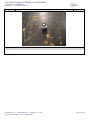
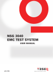
Photo 2
Test Setup – Radiated Emissions (below & above 1 GHz)
Supplemental Information:
Nemko USA, Inc. 802 N. Kealy Ave. Lewisville, TX
Tel: +1 972-436-9600 Fax: +1 972-436-9600
USA
Page 24 of 24
IMPORTANT NOTICE FOR TI REFERENCE DESIGNS
Texas Instruments Incorporated ("TI") reference designs are solely intended to assist designers (“Buyers”) who are developing systems that
incorporate TI semiconductor products (also referred to herein as “components”). Buyer understands and agrees that Buyer remains
responsible for using its independent analysis, evaluation and judgment in designing Buyer’s systems and products.
TI reference designs have been created using standard laboratory conditions and engineering practices. TI has not conducted any
testing other than that specifically described in the published documentation for a particular reference design. TI may make
corrections, enhancements, improvements and other changes to its reference designs.
Buyers are authorized to use TI reference designs with the TI component(s) identified in each particular reference design and to modify the
reference design in the development of their end products. HOWEVER, NO OTHER LICENSE, EXPRESS OR IMPLIED, BY ESTOPPEL
OR OTHERWISE TO ANY OTHER TI INTELLECTUAL PROPERTY RIGHT, AND NO LICENSE TO ANY THIRD PARTY TECHNOLOGY
OR INTELLECTUAL PROPERTY RIGHT, IS GRANTED HEREIN, including but not limited to any patent right, copyright, mask work right,
or other intellectual property right relating to any combination, machine, or process in which TI components or services are used.
Information published by TI regarding third-party products or services does not constitute a license to use such products or services, or a
warranty or endorsement thereof. Use of such information may require a license from a third party under the patents or other intellectual
property of the third party, or a license from TI under the patents or other intellectual property of TI.
TI REFERENCE DESIGNS ARE PROVIDED "AS IS". TI MAKES NO WARRANTIES OR REPRESENTATIONS WITH REGARD TO THE
REFERENCE DESIGNS OR USE OF THE REFERENCE DESIGNS, EXPRESS, IMPLIED OR STATUTORY, INCLUDING ACCURACY OR
COMPLETENESS. TI DISCLAIMS ANY WARRANTY OF TITLE AND ANY IMPLIED WARRANTIES OF MERCHANTABILITY, FITNESS
FOR A PARTICULAR PURPOSE, QUIET ENJOYMENT, QUIET POSSESSION, AND NON-INFRINGEMENT OF ANY THIRD PARTY
INTELLECTUAL PROPERTY RIGHTS WITH REGARD TO TI REFERENCE DESIGNS OR USE THEREOF. TI SHALL NOT BE LIABLE
FOR AND SHALL NOT DEFEND OR INDEMNIFY BUYERS AGAINST ANY THIRD PARTY INFRINGEMENT CLAIM THAT RELATES TO
OR IS BASED ON A COMBINATION OF COMPONENTS PROVIDED IN A TI REFERENCE DESIGN. IN NO EVENT SHALL TI BE
LIABLE FOR ANY ACTUAL, SPECIAL, INCIDENTAL, CONSEQUENTIAL OR INDIRECT DAMAGES, HOWEVER CAUSED, ON ANY
THEORY OF LIABILITY AND WHETHER OR NOT TI HAS BEEN ADVISED OF THE POSSIBILITY OF SUCH DAMAGES, ARISING IN
ANY WAY OUT OF TI REFERENCE DESIGNS OR BUYER’S USE OF TI REFERENCE DESIGNS.
TI reserves the right to make corrections, enhancements, improvements and other changes to its semiconductor products and services per
JESD46, latest issue, and to discontinue any product or service per JESD48, latest issue. Buyers should obtain the latest relevant
information before placing orders and should verify that such information is current and complete. All semiconductor products are sold
subject to TI’s terms and conditions of sale supplied at the time of order acknowledgment.
TI warrants performance of its components to the specifications applicable at the time of sale, in accordance with the warranty in TI’s terms
and conditions of sale of semiconductor products. Testing and other quality control techniques for TI components are used to the extent TI
deems necessary to support this warranty. Except where mandated by applicable law, testing of all parameters of each component is not
necessarily performed.
TI assumes no liability for applications assistance or the design of Buyers’ products. Buyers are responsible for their products and
applications using TI components. To minimize the risks associated with Buyers’ products and applications, Buyers should provide
adequate design and operating safeguards.
Reproduction of significant portions of TI information in TI data books, data sheets or reference designs is permissible only if reproduction is
without alteration and is accompanied by all associated warranties, conditions, limitations, and notices. TI is not responsible or liable for
such altered documentation. Information of third parties may be subject to additional restrictions.
Buyer acknowledges and agrees that it is solely responsible for compliance with all legal, regulatory and safety-related requirements
concerning its products, and any use of TI components in its applications, notwithstanding any applications-related information or support
that may be provided by TI. Buyer represents and agrees that it has all the necessary expertise to create and implement safeguards that
anticipate dangerous failures, monitor failures and their consequences, lessen the likelihood of dangerous failures and take appropriate
remedial actions. Buyer will fully indemnify TI and its representatives against any damages arising out of the use of any TI components in
Buyer’s safety-critical applications.
In some cases, TI components may be promoted specifically to facilitate safety-related applications. With such components, TI’s goal is to
help enable customers to design and create their own end-product solutions that meet applicable functional safety standards and
requirements. Nonetheless, such components are subject to these terms.
No TI components are authorized for use in FDA Class III (or similar life-critical medical equipment) unless authorized officers of the parties
have executed an agreement specifically governing such use.
Only those TI components that TI has specifically designated as military grade or “enhanced plastic” are designed and intended for use in
military/aerospace applications or environments. Buyer acknowledges and agrees that any military or aerospace use of TI components that
have not been so designated is solely at Buyer's risk, and Buyer is solely responsible for compliance with all legal and regulatory
requirements in connection with such use.
TI has specifically designated certain components as meeting ISO/TS16949 requirements, mainly for automotive use. In any case of use of
non-designated products, TI will not be responsible for any failure to meet ISO/TS16949.
Mailing Address: Texas Instruments, Post Office Box 655303, Dallas, Texas 75265
Copyright © 2013, Texas Instruments Incorporated