1
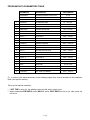
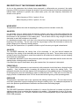
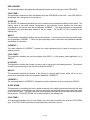
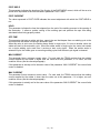
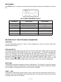
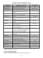
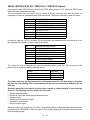
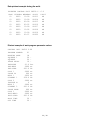
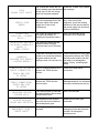
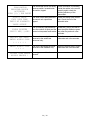
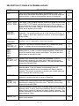
DIAGNOSTIC MENU PARAMETERS TABLE
PARAMETER
PARAMETER DESCRIPTION
VALUE RANGE
SOFTWARE VER.
This is the software version of the inverter
1.08
DRIVERS ERROR
This is the status of the control drivers
CAPACITORS
This indicates the voltage value of the capacitors
EMERGENCY
This indicates that inverter emergency inlet has
intervened with ERR. Vice versa, then OK is
displayed
OK – ERR
WELD - NO WELD
If the inverter inlet is on weld, then it displays OK
while if it is on no weld it displays ERR
OK – ERR
CHECK WELD
Not used
START BOOSTER
It indicates that the cycle start control has been given
to the inverter welding inlet with OK or it is on hold
with ERR
OK – ERR
THERMOSTAT
This indicates if the safety thermostat of the inverter
has tripped by displaying ERR. Vice versa, then OK is
displayed
OK – ERR
EV WATER
It indicates if the outlet controlling the inverter water
solenoid valve is active
ON – OFF
READY BOOSTER
By displaying OK, it indicates that the inverter has
finished charging the capacitors and is ready to weld.
Vice versa, it displays ERR
OK – ERR
WRONG BOOSTER
It indicates that the inverter has experienced either an
out-of-limit or excessive or faulty current supply (OK),
while, if the current supply is within the limits, the
parameter is correct on the outlets (ERR).
OK – ERR
LOCK BOOSTER
During the welding process the inverter is in the OK
condition while in the welding hold phase it is in the
ERR condition.
OK – ERR
TEMP. BOARD
It indicates the temperature on the board 50261
25.5*
TEMP. SINK
It indicates the temperature on the inverter radiator
30.5*
TRAFO I2T FAIL
It indicates if the thermal protection has intervened on
the welding transformer’s primary
V. SW. DRIVER
It indicates the 50256 driver board’s version
DRIVER LED 1
It indicates Led 1 status
ON – OFF*
DRIVER LED 2
It indicates Led 2 status
ON – OFF*
DRIVER LED 3
It indicates Led 3 status
ON – OFF*
DRIVER LED 4
It indicates Led 4 status
ON – OFF*
DRIVER LED 5
It indicates Led 5 status
ON – OFF*
NONE – DRV1 / 2
0 – ~ 700 V
Not used
ON – OFF
2.00*
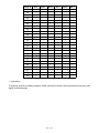
* The data is displayed only if the communication cable item 22890 is connected. Please, refer to the
installation menu for further information.
FACTORY RESERVED MENU
This menu is reserved to and can be accessed by authorized personnel only.
21 / 42