1
CNC 8055 MC
Operating Manual
Ref. 9909 (in)
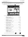
INDEX
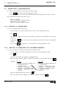
VERSION HISTORY
INTRODUCCIÓN
Safety conditions ......................................................................................................................... 3
Reshipment conditions ............................................................................................................... 5
Fagor documentation for the 8055MC CNC ................................................................................ 6
Contents of this manual .............................................................................................................. 7
1. CONFIGURATIONS
1.1
1.2
1.3
1.4
1.4.1
1.4.2
1.4.3
1.4.4
1.4.5
1.4.6
1.5
1.6
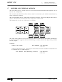
With 9" Amber, 10" Color, 11" LCD or 14" Color monitor ....................................................... 2
With 14" color monitor with alphanumeric keyboard ............................................................. 3
With 11" LCD monitor with full keyboard .............................................................................. 4
Monitors ................................................................................................................................ 5
9" Amber monitor .................................................................................................................. 5
10" Color monitor .................................................................................................................. 7
11" LCD monitor ................................................................................................................... 9
11" LCD monitor with full keyboard .................................................................................... 11
14" Color Monitor ............................................................................................................... 13
14" color monitor with alphanumeric keyboard ................................................................... 15
Specific MC model KEYBOARD ......................................................................................... 17
Keyboard switcher board ..................................................................................................... 19
2. GENERAL CONCEPTS
2.1
2.2
2.2.1
2.3
2.4
2.5
Keyboard ............................................................................................................................... 1
General .................................................................................................................................. 2
General logic outputs of the CNC .......................................................................................... 4
Power-up ............................................................................................................................... 5
Operating in 8055M mode with an MC keyboard .................................................................. 6
Video off ................................................................................................................................ 6
3. OPERATING IN JOG MODE
3.1
3.2
3.2.1
3.2.2
3.2.3
3.3
3.4
ii
Introduction .......................................................................................................................... 2
Axis Control .......................................................................................................................... 6
Work Units ............................................................................................................................ 6
Coordinate preset .................................................................................................................. 6
Handling the Feedrate of the Axes (F) ..................................................................................... 6
Search for Machine reference zero (home) .............................................................................. 7
Manually moving the machine .............................................................................................. 8
3.4.1
3.4.2
3.4.3
3.4.4
3.4.5
3.5
3.5.1
3.5.1.1
3.5.2
3.5.2.1
3.5.2.2
3.5.2.3
3.6
3.7
3.8
Continuous Movement .......................................................................................................... 8
Incremental movement .......................................................................................................... 9
Movement by means of Electronic Handwheel ..................................................................... 10
Feed handwheel ................................................................................................................... 11
Master Handwheel ............................................................................................................... 12
Tool control ......................................................................................................................... 13
Tool change ......................................................................................................................... 14
Variable tool change point ................................................................................................... 15
Tool calibration ................................................................................................................... 16
Define the tool in the tool table ........................................................................................... 17
Tool measurement ................................................................................................................ 18
Modify values while in execution ........................................................................................ 19
Spindle control .................................................................................................................... 20
Control of external devices .................................................................................................. 21
ISO code management ......................................................................................................... 22
4. WORKING WITH OPERATIONS OR CYCLES
4.1
4.1.1
4.1.2
4.2
4.3
4.3.1
4.3.2
4.4
4.4.1
4.5
4.5.1
4.5.2
4.5.3
4.6
4.6.1
4.7
4.7.1
4.8
4.8.1
4.9
4.9.1
4.10
4.10.1
4.11
4.11.1
4.12
4.12.1
4.13
4.13.1
4.13.2
4.13.3
4.13.4
4.13.5
Operation editing mode ......................................................................................................... 2
Definition of the machining conditions ................................................................................. 3
Safety plane ........................................................................................................................... 3
Simulation and execution of the operation ............................................................................. 4
Profile milling operation........................................................................................................ 5
Defining data ......................................................................................................................... 6
Profile definition (level 2)...................................................................................................... 7
Surface Milling operation ...................................................................................................... 8
Defining data ......................................................................................................................... 8
Pocket cycle with a profile ................................................................................................... 10
Data definition .................................................................................................................... 12
Profile definition ................................................................................................................. 13
Examples of profile definition ............................................................................................. 14
Rectangular and Circular Boss cycles .................................................................................. 16
Data definition .................................................................................................................... 17
Rectangular (2 levels) and Circular pocket cycles ................................................................ 18
Data definition .................................................................................................................... 19
Positioning (2 levels) ........................................................................................................... 21
Data definition .................................................................................................................... 22
Boring operation ................................................................................................................. 23
Data definition .................................................................................................................... 23
Reaming operation .............................................................................................................. 24
Data definition .................................................................................................................... 24
Tapping operation ............................................................................................................... 25
Data definition .................................................................................................................... 26
Drilling (2 levels) and Center punching operations .............................................................. 27
Data definition .................................................................................................................... 29
Multiple positioning ........................................................................................................... 30
Multiple positioning at random points ................................................................................ 31
Multiple positioning in a straight line ................................................................................. 32
Multiple positioning in an arc (bolt-hole pattern) ................................................................ 34
Multiple positioning in a parallelogram pattern ................................................................... 36
Multiple positioning in a grid pattern .................................................................................. 37
ii
5. STORAGE OF PROGRAMS
5.1
5.2
5.2.1
5.3
5.3.1
5.4
5.5
5.6
5.6.1
5.6.2
5.6.3
5.6.4
List of stored programs .......................................................................................................... 2
See content of a program ........................................................................................................ 3
Seeing the operations in detail ............................................................................................... 3
Edit a new part-program ......................................................................................................... 4
Storage of an operation or cycles ........................................................................................... 4
Erasing a part-program ........................................................................................................... 5
Copy a part-program in another ............................................................................................. 5
Modifying a part-program ...................................................................................................... 6
Erasing an operation .............................................................................................................. 6
Moving an operation to another position ............................................................................... 6
Adding or inserting a new operation ...................................................................................... 7
Modifying an already existing operation ............................................................................... 7
6. EXECUTION AND SIMULATION
6.1
6.2
6.2.1
6.3
6.4
6.4.1
6.5
Simulating or executing an operation or cycle ....................................................................... 2
Simulating or executing a part-program ................................................................................. 3
Simulating or executing a section of a part-program ............................................................... 3
Simulating or executing a stored operation ............................................................................ 3
Execution Mode .................................................................................................................... 4
Tool inspection ..................................................................................................................... 5
Graphic representation ........................................................................................................... 6
APPENDIX
Keyboard selection ................................................................................................................................ 3
Key codes .............................................................................................................................................. 5
Logic outputs for key status .................................................................................................................. 7
Key inhibiting codes ............................................................................................................................. 9
iv
VERSION HISTORY (M)
(MILL MODEL)
Date:
May 1999
FEATURE
Software Version: 3.0x
AFFECTED M ANUAL & CHAPTERS
Portuguese language
Installation Manual
Chapter 3
Tangential Control
Installation Manual
Programming Manual
Chapters 9, 10, Appendix
Chapters 6, 13, Appendix
PLC. User registers R1 through R499
Installation Manual
Programming Manual
Chapters 6, 7, Appendix
Chapter 13
CNC status screen
Operation Manual
Chapter 8
Hard disk (HD)
Installation Manual
Chapters 1, 3, Appendix
HD Diagnosis
Operation Manual
Chapter 12
Integrate the HD into an outside PC network
Installation Manual
Chapter 3
Consult directories, delete, rename and copy programs in
the same or other device
Operation Manual
Programming Manual
Chapters 1, 7
Chapter 1
Ejecution and simulacion from RAM memory, Memkey
Card, HD or serial line.
Operation Manual
Chapters 1, 3,
It is possible to execute (EXEC) and open (OPEN) a
program (to be edited) stored in any device.
Programming Manual
Chapter 14, Appendix
MC option. Tool calibration screen.
When defining R and L; I and K are initialized
If I=0 and K=0; I and K are initialized
Operation Manual
Chapter 3
MC option. ISO management, also as MDI
MC Operation Manual
Chapter 3
MC option. New way to handle safety planes.
MC Operation Manual
Chapter 4
MC option. New codes for specific keys.
MC Operation Manual
Appendix
Incline planes. The software travel limits are monitored in
JOG movements.
Version history (M) - 1
2 - Version history (M)
8055MC CNC
INTRODUCTION
Introduction - 1
Safety conditions
8055MC CNC
SAFETY CONDITIONS
Read the following safety conditions in order to prevent accidents to staff and damage to this product
and any products connected to it.
The equipment may only be repaired by Fagor Automation authorized staff.
Fagor Automation will not assume responsibility for any physical or material harm stemming from
failure to comply with these basic safety norms.
Precautions against accidents
Before powering up the equipment make sure it is connected to ground
In order to prevent electric shocks make sure the ground connections have been properly made.
Do not work in damp atmospheres
To prevent electric shocks always work in atmospheres with a relative humidity of under 90% with no
condensation at 45°C.
Do not work in explosive atmospheres
To avoid danger, physical harm or damage, do not work in explosive atmospheres.
Precautions to avoid damaging the product
Operating environment
This equipment is prepared for use in Industrial Environments, complying with directives and standards
in force in the European Union.
Fagor Automation will not assume any responsibility for any damage that it may cause or undergo if
it is set up in any other type of conditions (residential or household environments).
Install the equipment in a suitable place
Wherever possible, the CNC installation should be made well away from cooling liquids, chemicals, or
where it may be subject to impacts that could damage this.
The equipment complies with European electromagnetic compatibility directives. We nevertheless
recommend keeping it away from sources of electromagnetic disturbance, such as:
-
Powerful loads connected to the same mains as the equipment.
Nearby portable transmitter (Radiotelephones, amateur radio transmitters).
Nearby radio/TV transmitters.
Nearby arc welding machines.
Nearby high voltage lines.
Etc.
Environmental Conditions
The room temperature should be maintained in operating conditions should be between +5°C and
+45°C.
The room temperature that should be maintained in non-operating conditions should be between -25°C
and 70°C.
Introduction - 3
Safety conditions
8055MC CNC
Protection devices in the equipment itself
Power Source Module
Has two fast 3.15 Amp./ 250V. external fuses (F) fitted for protecting the mains input.
Axis Module
All the digital input/outputs are protected by means of 1 fast 3.15 Amp./ 250V. external fuse (F) against
overvoltages from the external power sources (over 33 Vdc.) and against connection of the power
source the wrong way round.
Input-output Module
All the digital input/outputs are protected by means of 1 fast 3.15 Amp./ 250V. external fuse (F) against
overvoltages from the external power sources (over 33 Vdc.) and against connection of the power
source the wrong way round.
Input-output and Copy Module
All the digital input/outputs are protected by means of 1 fast 3.15 Amp./ 250V. fuse (F) against
overvoltages from the external power sources (over 33 Vdc.) and against connection of the power
source the wrong way round.
Ventilator module
Has 1 or 2 external fuses fitted depending on the model.
The fuses are fast (F), 0.4 Amp./ 250V. for protecting the fans.
Monitor
The type of fuse depends on the type of monitor. See the identification label on the equipment itself.
Precautions to be taken during repairs
Do not touch the inside of the equipment
Only authorized Fagor Automation staff may handle the items located inside
the equipment.
Do not touch the connectors when the equipment is connected to the mains.
Before touching the connectors (input/outputs, feedback etc) make sure that
the equipment is not connected to the mains.
Safety symbols
Symbols that may appear in the manual
WARNING Symbol
This goes with text describing action or operations that could give rise to
accidents or damage of the equipment.
Symbols that may be found on the product
WARNING Symbol
This goes with text describing action or operations that could give rise to
accidents or damage of the equipment.
ELECTRIC SHOCK Symbol
Means that the point indicated could be under electrical voltage.
GROUND PROTECTION Symbol
Means that the point indicated must be connected up to the central machine
ground point for protecting people and equipment.
Introduction - 4
Reshipment conditions
8055MC CNC
RESHIPMENT CONDITIONS
If the Monitor of the Central Processing Unit has to be sent back, please pack this in its original box
with the original packing material. If the original packing material is not available, please pack this as
follows:
1.- Obtain a cardboard box whose 3 internal sizes should be at least 15 cm (6 inches) larger than the
equipment. The cardboard used for the box should withstand 170 Kg (375 pounds).
2.- If this is to be sent to a Fagor Automation office to be repaired, enclose a label with the device stating
its owner, address, name of the person to be contacted, type of device, series number, symptoms
and brief description of the fault.
3.- Wrap the equipment in a polyethylene roll or similar material to protect this.
If the monitor is to be shipped, provide special protection for the glass part of the screen.
4.- Pad the equipment in the cardboard box by filling this with polyurethane foam on all sides.
5.- Seal the cardboard box with packing tape or industrial staples.
Introduction - 5
Fagor Documentation
for the CNC 8055TC
8055MC CNC
FAGOR DOCUMENTATION FOR THE
8055MC CNC
The 8055MC CNC is based on the 8055M CNC, and has inside all the features of the 8055T CNC
plus the specific features of the MC mode.
For this reason, it has the specific documentation for this model and all the documents for the
8055M CNC model.
CNC 8055 OEM Manual
For the manufacturer of the machine or the person in charge of carrying
out the installation and set up of the CNC.
This is the same for models 8055-M, 8055-T and 8055-MC. It has the
Installation manual inside.
CNC 8055-M USER Manual
For the final user, that is, the person who is going to work with the CNC
in the 8055-M mode.
It has 2 manuals inside:
Operation Manual
Programming manual
describing how to operate the CNC.
describing how to program the CNC.
CNC 8055-MC USER Manual This is for the final user, meaning the person who is going to work with
the CNC in the 8055-MC mode.
DNC 8050 Software Manual
For the persons who are to use the DNC 8050 communication software
option.
DNC 8050 Protocol Manual
For those who wish to make their own DNC communication, without
using the DNC 8050 communication software option.
FLOPPY DISK Manual
For those who use the Fagor disc drive. This manual shows how said drive
should be used.
Introduction - 6
8055MC CNC
Contents of this manual
CONTENTS OF THIS MANUAL
This manual is made up of the following sections:
Index
History of versions
Introduction
Summary of the safety conditions.
Reshipment Conditions.
List of Fagor Documents for the 8055 CNC.
Contents of this Manual.
Chapter 1
Configurations.
Explains the 2 possible configurations, the basic one and the extended one.
Shows how the connection of the different items should be made and the characteristics of each
of these.
Chapter 2
General Concepts.
Keyboard layout and programs supplied by Fagor Automation.
Variables and parameters specified for the 8055MC model.
Describes the possibilities for using 1, 2 o 3 electronic handwheels.
How to carry out CNC power up and how to access 8055M operating mode.
Chapter 3
Operating in manual mode.
Gives the values displayed by the CNC in this operating mode.
How to select the operating units, axis feedrate, etc..
How to make a search for machine reference zero (home).
Moving the machine manually or by means of electronic handwheels.
Tool Control. Tool changing, calibration and measuring.
Spindle Control in rpm and at Constant surface speed.
Control of the external devices.
Chapter 4
Operating with operations or cycles.
Shows how to select each of the operations or cycles.
Explains how to define all the data for each of the operations.
Shows how to define the machining conditions for the operation.
Chapter 5
Storing programs.
Shows how to access the list of programs stored.
Explains how to see the content of a program or one of its operations
Explains how to edit, erase or copy a new part-program.
Shows how to modify a part-program or one of its operations.
Chapter 6
Execution and simulation
Describes how to simulate or execute an operation or part-program.
Appendix
Selection of keyboards in the extended configuration.
Key codes, to be handled in the PLC
Introduction - 7
1.
CNC 8055MC
Configurations
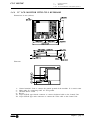
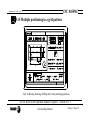
1. CONFIGURATIONS
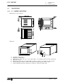
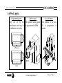
The CNC 8055MC is modular and must have the following elements:
Central Unit (CPU):
Is located usually in the electrical cabinet and there are 2 models: for 3 and
6 modules. For further information, see the Installation manual Chapter 1.
Monitor:
There are several models: 9" Amber, 10" Color, 11" LCD and 14" Color.
The dimensions, enclosures and connections them all are described later on in this
chapter.
Keyboard:
There is a specific keyboard to operate it in MC mode. Its dimensions and
connections are described later on in this chapter.
When operating in "not MC" mode (CNC installation and start-up and standard
8055 operating mode) the access to the alphanumeric keys is rather cumbersome
because one must press 2 keys for the CNC to assume the desired one.
Selects the A character
Selects the R character
In this cases, the following should be used:
a) The MC keyboard and a 14" color
monitor with alphanumeric keyboard
b) The 11" LCD monitor with full keyboard.
The MC keyboard is not required.
Chapter 1 - page 1
1.
1.1
1.1
Configurations
With 9" Amber, 10" Color, 11" LCD or 14" Color monitor
CNC 8055MC
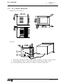
WITH 9" AMBER, 10" COLOR, 11" LCD OR 14" COLOR MONITOR
Central Unit - Specific MC keyboard connection
It is done through connector X1 of the CPU module. Fagor Automation supplies the cable for
this connection.
The characteristics of the connector are described in Chapter 1 of the Installation module (CNC
configuration) in the section regarding the CPU module.
The dimensions, enclosure and connector location on the keyboard is described later on in this
chapter.
Central Unit-Monitor connection
It is done through connector X2 of the CPU module. Fagor Automation supplies the cable for
this connection.
The characteristics of the connector are described in Chapter 1 of the Installation module (CNC
configuration) in the section regarding the CPU module.
The dimensions, enclosure and connector location on the keyboard is described later on in this
chapter.
Configuration setting.
General machine parameter CUSTOMTY (P92) = 0
Chapter 1 - page 2
CNC 8055MC
1.2
1.
1.2
Configurations
With 14" color monitor with alphanumeric keyboard
WITH 14" COLOR MONITOR WITH ALPHANUMERIC KEYBOARD
Central Unit - Keyboard connection
It is done through connector X1 of the CPU module and through the keyboard switcher board.
Fagor Automation supplies the cables for this connection.
The characteristics of the connector are described in Chapter 1 of the Installation module (CNC
configuration) in the section regarding the CPU module.
The dimensions, enclosure and connector location on the keyboard is described later on in this
chapter.
The dimensions, connectors of the keyboard switcher board as well as how to select the keyboard
active at the time is described later on in this chapter.
Central Unit - Monitor connection
It is done through connector X2 of the CPU module. Fagor Automation supplies the cable for
this connection.
The characteristics of the connector are described in Chapter 1 of the Installation module (CNC
configuration) in the section regarding the CPU module.
The dimensions, enclosure and connector location on the keyboard is described later on in this
chapter.
Configuration setting
General machine parameter CUSTOMTY (P92) = 0
Chapter 1 - page 3
1.
1.3
1.3
Configurations
With 11" LCD monitor with full keyboard
CNC 8055MC
WITH 11" LCD MONITOR WITH FULL KEYBOARD
Central Unit - Monitor / Keyboard
It is connected to the keyboard through connector X1 of the CPU module and to the monitor
through connector X2 of the CPU module.
Fagor Automation supplies the cables for these connections.
The characteristics of the connectors are described in Chapter 1 of the Installation module (CNC
configuration) in the section regarding the CPU module.
The dimensions, enclosure and connection of the Monitor / Keyboard is described later on in this
chapter.
Configuration setting.
General machine parameter CUSTOMTY (P92) = 255
Chapter 1 - page 4
CNC 8055MC
1.4
1.
Configurations
1.4
Monitors
1.4.1 9" Amber Monitor
MONITORS
1.4.1 9" AMBER MONITOR
Dimensions in mm (inches):
Elements:
1.2.3.4.5.6.7.-
Contrast setting knob
Brightness setting knob
Mains fuses. 2 fast ones (F), 1 per mains phase, of 3.15Amp./250V for mains protection.
ON/OFF switch
Mains plug. The plug provided should be used to connect it to 220V AC and ground.
Ground terminal. Used to connect the general machine ground. Metric 6mm.
25-pin SUB-D type male connector to connect it with the Central Unit.
Chapter 1 - page 5
1.
Configurations
1.4
Monitors
1.4.1 9" Amber Monitor
CNC 8055MC
Enclosure:
In order to guarantee proper ambient conditions, the shortest distance, in millimeters, that should be
left between each of the Monitor walls and the enclosure in which this is placed, must be as follows:
When a fan is used to improve the ventilation of the enclosure a fan with direct current motor should
be used, as alternating current (AC) motors product magnetic fields which could distort the images
displayed on the screen.
The temperature inside the enclosure should be between 0 and 50°C (32 to 122°F).
Chapter 1 - page 6
CNC 8055MC
1.
Configurations
1.4
Monitors
1.4.2 10" Color Monitor
1.4.2 10" COLOR MONITOR
Dimensions in mm (inches):
Elements:
1- Mains plug. The plug provided should be used to connect it to 220V AC and ground.
2- Ground terminal. Used to connect the general machine ground. Metric 6mm.
X2- 25-pin SUB-D type male connector to connect it with the Central Unit.
Chapter 1 - page 7
1.
Configurations
1.4
Monitors
1.4.2 Monitor 10" Color
CNC 8055MC
Enclosure:
In order to guarantee proper ambient conditions, the shortest distance, in millimeters, that should be
left between each of the Monitor walls and the enclosure in which this is placed, must be as follows:
When a fan is used to improve the ventilation of the enclosure a fan with direct current motor should
be used, as alternating current (AC) motors product magnetic fields which could distort the images
displayed on the screen.
The temperature inside the enclosure should be between 0 and 50°C (32 to 122°F).
Chapter 1 - page 8
CNC 8055MC
1.
Configurations
1.4
Monitors
1.4.3 11" LCD Monitor
1.4.3 11" LCD MONITOR
Dimensions in mm (inches):
Elements:
123.4-
Mains plug. The plug provided should be used to connect it to 220V AC and ground.
Ground terminal. Used to connect the general machine ground. Metric 6mm.
ON/OFF power switch.
25-pin SUB-D type female connector to connect it with the Keyboard.
X2 25-pin SUB-D type male connector to connect the video cables to the Central Unit.
Chapter 1 - page 9
1.
Configurations
1.4
Monitors
1.4.3 11" LCD Monitor
CNC 8055MC
Enclosure:
In order to guarantee proper ambient conditions, the shortest distance, in millimeters, that should be
left between each of the Monitor walls and the enclosure in which this is placed, must be as follows:
When a fan is used to improve the ventilation of the enclosure a fan with direct current motor should
be used, as alternating current (AC) motors product magnetic fields which could distort the images
displayed on the screen.
The temperature inside the enclosure should be between 0 and 50°C (32 to 122°F).
Note:
Defective Pixels.
Due to the current status of the Color TFT LCD technology, all manufacturers consider good
LCDs those having a certain number of defective pixels. The widely accepted criteria are
basically: the number of defective pixels or sub-pixels and their concentration on the LCD
surface.
Chapter 1 - page 10
CNC 8055MC
1.
Configurations
1.4
Monitors
1.4.4 11" LCD monitor with full keyboard
1.4.4 11" LCD MONITOR WITH FULL KEYBOARD
Dimensions in mm (inches):
Elements:
1.2.3.4.X1
X2
Ground terminal. Used to connect the general ground of the machine. It is metric 6mm.
Mains plug for connecting 220V AC and ground.
ON/OFF Power switch
Buzzer.
25-pin SUB-D type female connector to connect keyboard cable to the Central Unit.
25-pin SUB-D type male connector to connect the video cable to the Central Unit.
Chapter 1 - page 11
1.
Configurations
1.4
Monitors
1.4.4 11" LCD monitor with full keyboard
CNC 8055MC
Enclosure:
In order to guarantee proper ambient conditions, the shortest distance, in millimeters, that should be
left between each of the Monitor walls and the enclosure in which this is placed, must be as follows:
When a fan is used to improve the ventilation of the enclosure a fan with direct current motor should
be used, as alternating current (AC) motors product magnetic fields which could distort the images
displayed on the screen.
The temperature inside the enclosure should be between 0 and 50°C (32 to 122°F).
Note:
Defective Pixels.
Due to the current status of the Color TFT LCD technology, all manufacturers consider good
LCDs those having a certain number of defective pixels. The widely accepted criteria are
basically: the number of defective pixels or sub-pixels and their concentration on the LCD
surface.
Chapter 1 - page 12
CNC 8055MC
1.
Configurations
1.4
Monitors
1.4.5 14" Color monitor
1.4.5 14" COLOR MONITOR
Dimensions in mm (inches):
Elements:
1.- Ground terminal. Used to connect the general ground of the machine. It is metric 6mm.
2.- Mains plug for connecting 220V AC and ground.
X2 25-pin SUB-D type male connector to connect the video cable to the Central Unit.
Chapter 1 - page 13
1.
Configurations
1.4
Monitors
1.4.5 14" Color Monitor
CNC 8055MC
Enclosure:
In order to guarantee proper ambient conditions, the shortest distance, in millimeters, that should be
left between each of the Monitor walls and the enclosure in which this is placed, must be as follows:
When a fan is used to improve the ventilation of the enclosure a fan with direct current motor should
be used, as alternating current (AC) motors product magnetic fields which could distort the images
displayed on the screen.
The temperature inside the enclosure should be between 0 and 50°C (32 to 122°F).
Chapter 1 - page 14
CNC 8055MC
1.
Configurations
1.4
Monitors
1.4.6 14" color monitor with alphanumeric keyboard
1.4.6 14" COLOR MONITOR WITH ALPHANUMERIC KEYBOARD
Dimensions in mm (inches):
Elements:
1.2.3.X1
X2
X3
Ground terminal. Used to connect the general ground of the machine. It is metric 6mm.
Mains plug for connecting 220V AC and ground.
Buzzer.
25-pin SUB-D type female connector to connect keyboard cable to the Central Unit.
25-pin SUB-D type male connector to connect the video cable to the Central Unit.
Reserved.
Chapter 1 - page 15
1.
Configurations
1.4
Monitors
1.4.6 14" color monitor with alphanumeric keyboard
CNC 8055MC
Enclosure:
In order to guarantee proper ambient conditions, the shortest distance, in millimeters, that should be
left between each of the Monitor walls and the enclosure in which this is placed, must be as follows:
When a fan is used to improve the ventilation of the enclosure a fan with direct current motor should
be used, as alternating current (AC) motors product magnetic fields which could distort the images
displayed on the screen.
The temperature inside the enclosure should be between 0 and 50°C (32 to 122°F).
Chapter 1 - page 16
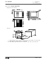
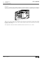
CNC 8055MC
1.5
1.
1.5
Configurations
Specific MC model keyboard
SPECIFIC MC MODEL KEYBOARD
Dimensions in mm (inches):
Elements:
1.- 25-pin SUB-D type female connector to connect the keyboard with the Central Unit or with
the keyboard switcher board.
2.- Ground terminal.
3.- Buzzer
4.- Buzzer volume adjusting potentiometer
Chapter 1 - page 17
1.
1.5
Configurations
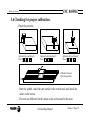
Specific MC model keyboard
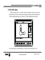
Enclosure:
The keyboard must be mounted as indicated below:
Chapter 1 - page 18
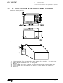
CNC 8055MC
1.
1.6
CNC 8055MC
1.6
Configurations
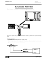
keyboard switcher board
KEYBOARD SWITCHER BOARD
It must be used when having an MC keyboard and a 14" color monitor with alphanumeric keyboard.
It is used to select the keyboard attended to by the Central Unit: the MC keyboard or the one at the
monitor.
Dimensions in mm (inches) and elements:
X1 25-pin SUB-D type female connector for connection with the Central Unit.
X2 25-pin SUB-D type female connector for connection with the keyboard of the monitor.
X3 25-pin SUB-D type female connector for connection with the MC keyboard.
X4 3-pin WEIDMÜLLER type male connector used for selecting the keyboard attended to by the
Central Unit.
Pin
1
Value
Function
0V
CNC attends to the 8050MC keyboard
24V
The CNC attends to the 8050M keyboard
Input
2
--
--
Not used at this time
3
Input
0V
External power supply
Connector X4 may be controlled either from the electrical cabinet or by the operator by means of a
switch.
If connector X4 is not under power, the CNC attends to the MC keyboard.
The maximum cable length permissible between the Central Unit and the Keyboard is 25m (82 pies).
The appendix of this manual includes a section with examples about selecting keyboards.
Chapter 1 - page 19
2.
2.1
8055MC CNC
General Concepts
Keyboard
2. GENERAL CONCEPTS
2.1
KEYBOARD
Alphanumeric keys and command keys.
Selects character X
Selects character A
Selects character R
Specific keys for the MC model
Enable Selection and definition of Machining Operations
Governing external devices
Selecting the spindle’s operating mode
Selecting single or automatic execution mode
The JOG key
Enables Moving the axes of the machine
Governing the spindle
Modifying the feedrate of the axes and the spindle
speed
Starting and stopping execution
Chapter 2 - page 1
2.
2.2
General Concepts
General
8055MC CNC
2.2 GENERAL
The 8055MC CNC is based on the 8055M CNC and has inside all the performance features of the
8055M CNC plus the specific features of the MC mode.
For example, the setting of the numerical Control must be done in 8055M mode.
In the MC operating mode the programs P900000 to P999999 are reserved for the CNC itself, that
is, these cannot be used as part-programs by the user as they have a special significance.
Furthermore, to be able to work in MC mode, the CNC has to have in its memory programs P999997
and P999998, which are supplied by Fagor Automation.
Every time the CNC detects a new software version, updates these programs automatically and makes
a backup copy of the old ones in the configuration card (CARD A).
Also routines 0000 a 8999 are free for use and routines 9000 to 9999 are reserved for the CNC itself.
Warning: Programs P999997 and P999998 are associated with the software version.
Fagor Automation shall not be held responsible of any possible malfunction if
programs P999997 and P999998 contained in user RAM memory have been erased
or do not correspond to the software version.
Some of the routines reserved for the CNC itself have the following meaning:
9998
9999
Routine to be executed by the CNC at the beginning of each part-program.
Routine to be executed by the CNC at the end of each part-program.
Every time a new part-program is edited the CNC adds a call to the corresponding
routine at the beginning and end of each program.
Warning
Both subroutines must be defined by the machine manufacturer even if no operation
is to be carried out at the beginning or at the end of the part-program.
Otherwise, the CNC will issue an error when attempting to run a part-program.
Example of how to define subroutine 9998.
(SUB 9998) ; Definition of subroutine 9998.
; Programmed blocks defined by the machine manufacturer
(RET)
; End of subroutine
Chapter 2 - page 2
2.
2.2
8055MC CNC
General Concepts
General
Some of the programs reserved for the CNC itself have the following meaning:
P999998
This is a routines program used by the CNC for interpreting the programs edited in MC
format and executing these afterwards.
Warning
No modifications of this program are allowed. If this program is
modified or erased, Fagor Automation will not be held responsible
for the performance of the CNC.
If the manufacturer needs to create his own subroutines (home
search subroutine, tool change, etc. ...) as well as subroutines
9998 and 9999 should be included in another program, for
example P999999.
P999997
This is a text program which contains:
All the phrases and texts displayed on the different screens in the MC mode.
The help texts for the icons in work cycles shown at the bottom left side of the screen.
The messages (MSG) and errors (ERR) to be issued at the MC model.
All these texts, messages and errors may be translated into the desired language.
Points to consider:
All the lines of the program have to start with the character ";"
If a line starts with ";;", the CNC will understand that the whole line is a program
comment.
The format of a line is as follows:
";Nr. of text - explanatory remark (not displayed) - $Text to be displayed"
Examples
;; General text ............................... The CNC treats this as a remark
;;44 Feedrate $M/MIN ................. The CNC treats this as a remark.
;44 $M/MIN .................................. This is message 44 and the text "M/MIN" is
displayed
;;44 Feedrate $M/MIN ................. This is message 44, and has the explanatory
remark "Feedrate" which is not displayed and the
text
"M/MIN" is shown.
Notes regarding messages:
The format must be respected. Only the text after "SAVEMSG:" may be translated
Example:
Original:
Translated:
N9500(MSG"SAVEMSG: DRILLING 1")
N9500(MSG"SAVEMSG: 1. ZULAKETA ZIKLOA")
Notes regarding errors:
The format must be respected. Only the text between quotes( "xxxx") may be
translated
Example:
Original:
N9000(ERROR"DRILLING CYCLE 1: F=0")
Translated:
N9000(ERROR"1. ZULAKETA ZIKLOA: f=0")
Warning
When modifying program 999997, it is recommended to make a
backup copy because the CNC replaces it every time another
language is selected or the software version is updated.
P998000 ... P998999 Are the profiles defined by the user by means of the profile editor and
corresponding to the pocket cycle with profiles. In the MC mode, the user defines them
with three digits (0 through 999) and the CNC stores them internally as P 998xxx.
P997000 ... P997999 Are the profiles defined by the user by means of the profile editor and
corresponding to the profile milling operation. In the P 997xxx.
Chapter 2 - page 3
2.
General Concepts
2.2
General
2.2.1 General logic outputs of the CNC
2.2.1
8055MC CNC
GENERAL LOGIC OUTPUTS OF THE CNC
The general logic output CUSTOM (M5512) shows the CNC the operation mode that is selected:
CUSTOM (M5512) = 0
CUSTOM (M5512) = 1
Operating mode CNC 8055 M is selected.
Operating mode CNC 8055 MC is selected.
When having two keyboards, MC keyboard and an 14" monitor with keyboard, this variable can be
used in the PLC:
- to govern the keyboard switcher board.
- to know the source of the keys and inhibit the desired ones.
SELECT0 a SELECT7 (M5524 a M5531)
The general logic outputs "SELECT" indicate the position selected at each multi-position switch
of the keyboard.
Pos ition
0
0
0
0
Handwheel x 10
0
0
0
1
Handwheel x 1
0
0
1
0
JOG 10000
0
0
1
1
JOG 1000
0
1
0
0
JOG 100
0
1
0
1
JOG
10
0
1
1
0
JOG
1
0
1
1
1
1
0
0
0
Continuous JOG
Pos ition
Chapter 2 - page 4
SELECT3 SELECT2 SELECT1 SELECT0
Handwheel x 100
SELECT7 SELECT6 SELECT5 SELECT4
Feed Override 0%
0
0
0
0
Feed Override 2%
0
0
0
1
Feed Override 4%
0
0
1
0
Feed Override 10%
0
0
1
1
Feed Override 20%
0
1
0
0
Feed Override 30%
0
1
0
1
Feed Override 40%
0
1
1
0
Feed Override 50%
0
1
1
1
Feed Override 60%
1
0
0
0
Feed Override 70%
1
0
0
1
Feed Override 80%
1
0
1
0
Feed Override 90%
1
0
1
1
Feed Override 100%
1
1
0
0
Feed Override 110%
1
1
0
1
Feed Override 120%
1
1
1
0
2.
2.3
8055MC CNC
2.3
General Concepts
Power-up
POWER-UP
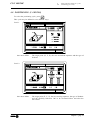
Both on CNC power-up and after the keystroke sequence:
the CNC acts as follows:
Shows «page 0» if it has been defined by the manufacturer. To access this operating mode, press
any key.
If there is no «page 0», the CNC will display the standard screen for the selected work mode.
There are two operating modes: MC mode and M mode. To switch from one mode to the other, press
The standard MC mode screen is:
Warning
CNC setting should be done in M mode.
Some errors must be eliminated in the M mode.
Chapter 2 - page 5
2.
2.4
2.5
General Concepts
Operating in 8055M mode with an MC keyboard
Video OFF
8055MC CNC
2.4 OPERATING IN 8055M MODE WITH AN MC KEYBOARD
The MC keyboard has been designed to also be able to operate in M mode. The alphanumeric
keyboard must be used for the keys replacing softkeys F1 to F7.
Alphanumeric keyboard:
The keys which replace softkeys F1 to F7 are:
To switch from one operating mode to another, press key sequence
2.5 VIDEO OFF
The CRT can be blanked out by hitting the keystroke sequence:
.
To recover the video signal, just press any key.
On the other hand, when receiving any message (PLC, program, etc.) the CNC also recovers the
display.
Chapter 2 - page 6
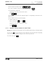
3.
8055MC CNC
Operating in JOG mode
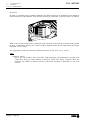
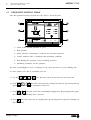
3. OPERATING IN JOG MODE
The standard MC operating mode screen is:
If one presses key
The CNC displays the special MC operating mode screen.
Chapter 3 - page 1
3.
3.1
3.1
Operating in JOG mode
Introduction
8055MC CNC
INTRODUCTION
The standard MC operating mode screen contains the following information:
1.- Clock
2.- This window can display the following data:
SBK
when the Single Block execution mode is selected.
DNC
when the DNC mode is activated.
P.....
number of the program selected.
Message «In Position» - «Execution» - «Interrupted» - «RESET»
PLC messages
3.- The CNC messages are shown in this window.
4.- This window can display the following data:
* The X, Y, Z coordinates of the axes.
* In small characters, the axis coordinates referred to machine zero reference (home). This
values are very useful when allowing the operator to set a tool change position (see zone 6).
The CNC does not show this data when text 33 has not defined in program 999997.
* The coordinates of the auxiliary axes which are defined.
* The real spindle rpm "S".
5.- The information shown in this window depends on the position of the left-hand switch.
In all cases the feedrate of the «F» axes that has been selected and the % of F which is being
applied are shown.
All the possible cases are shown below.
Chapter 3 - page 2
8055MC CNC
3.
3.1
Operating in JOG mode
Introduction
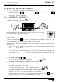
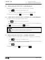
6.- This window displays, in large characters, the tool number «M» selected.
The offset number «D» associated with the tool. If the tool number and the offset number
coincide, the CNC will not display value «D».
The coordinates for the tool change point referred to home. The CNC does not display this
window when text 47 of program 999997 is not defined.
7.- This window shows all the details of the spindle :
* The actual spindle speed "S".
* The condition of the spindle. This is represented by an icon and can be turning to the right,
to the left or idle.
* The % of the spindle speed being applied.
* The active spindle range.
* The range of the active spindle. The CNC does not display this information when text 28 of
program 999997 is not defined.
8.- Whenever a work cycle is accessed, the CNC shows the help text associated with the icon
selected in this window.
This help text must be defined in P999997 program and be written in the desired language.
The format and the points to be considered in the P999997 program are detailed in Chapter 2.
9.- Reserved.
Chapter 3 - page 3
3.
3.1
Operating in JOG mode
Introduction
8055MC CNC
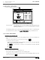
The special screen for MC operating mode contains the following information:
1.- Clock
2.- This window can display the following data:
SBK
when the Single Block mode of execution is selected.
DNC
when the DNC mode is active.
P.....
number of the program selected.
Message «In Position» - «Execution» - «Interrupted» - «RESET»
PLC messages
3.- The CNC messages are shown in this window.
4.- In manual operating mode this window does not display any data, but during execution, it shows
the lines of the program being executed.
5.- The X, Each axis has the following fields available:
COMMAND
States the coordinate programmed, that is, the position that the axis must
reach.
ACTUAL
States the actual coordinate or actual position of the axis.
TO GO
States the distance that the axis has still to go to reach the coordinate
programmed.
FOLLOWING ERROR Difference between the theoretical and real values of the position.
The spindle (S) has the following fields available:
THEORETICAL
theoretical speed S programmed.
RPM
speed in rpm.
FOLLOWING ERROR When operating with spindle guided stop (M19) this indicates the
difference between theoretical and real speeds.
The auxiliary axes only show the actual (real) axis position.
Chapter 3 - page 4
3.
3.1
8055MC CNC
Operating in JOG mode
Introduction
6.- This window shows the state of the «G» functions and the auxiliary functions «M» that are
activated. It also displays the value of variables.
PARMC
States the number of consecutive parts that have been executed with the same
program.
Whenever a new program is selected, this variable assumes value 0.
CYTIME
States the time elapsed during the execution of the parts. It is expressed in the
following
format: “hours : minutes : seconds : hundredths of second”.
Whenever the execution of a program is started, even though this is repetitive, this
variable assumes value 0.
TIMER
States the reading of the clock enabled by the PLC. It is expressed in format “hours
: minutes : seconds”.
7.- Reserved.
8.- Reserved.
Warning
Whenever a part-program or an operation stored as part of a part-program is
selected for simulation or execution, the CNC selects this part-program in the
top center window and highlights it next to the
symbol.
When the selected program is highlighted, the CNC acts as follows:
If
is pressed, the CNC executes the selected part-program.
If
is pressed the program is deselected, the CNC deletes it from the top
center window.
Chapter 3 - page 5
3.
3.2
Operating in JOG mode
Axis control
8055MC CNC
3.2 AXIS CONTROL
3.2.1 WORK UNITS
Whenever the MC work mode is accessed, the CNC assumes the work units, «mm or inches»,
«millimeters/minute or millimeters/revolution», etc., that are selected by machine parameter.
To modify these values the M work mode has to be accessed, modifying the relevant machine
parameter.
3.2.2 COORDINATE PRESET
Coordinate preset must be made axis to axis, in the following stages:
1st
Press the key for the axis required
,
or
The CNC will frame the position for said axis, to indicate that this is selected.
2nd
Enter the value required for preset of the axis.
To exit coordinate preset press
3rd
Press
so that the CNC assumes said value as the new value for the point.
The CNC requests confirmation of the command. Press
exit preset.
3.2.3
to confirm or
HANDLING THE FEEDRATE OF THE AXES (F)
To fix any particular value for the axis feedrate the following steps have to be carried out:
1st
Press
The CNC will frame the present value, to indicate that this is selected.
2nd
Enter the new feedrate required.
To exit coordinate preset press
3rd
Chapter 3 - page 6
Press
for the CNC to assume said value as the new feedrate for the axes.
to
3.
3.3
8055MC CNC
3.3
Operating in JOG mode
Search for machine reference zero
SEARCH FOR MACHINE REFERENCE ZERO (HOME)
The search for machine reference zero can be done in 2 ways:
- search for machine reference zero for all the axes.
- search for machine reference zero for only one axis.
Search for machine reference for all the axes
To carry out a search for machine reference zero for all axes the user should press key:
The CNC will request confirmation of the command (text 48 of program 999997)
Press
,The CNC will execute the machine reference zero routine defined by the
manufacture in the general machine parameter P34 (REFPSUB).
Warning:
After carrying out the search for machine reference zero (home)
position in this mode, the CNC saves the part zero or zero offset that
is active at the time.
A home search routine, general machine parameter P34 other than 0 has
to be defined. Otherwise the CNC will display the relevant error.
Search for machine reference zero for only one axis
To carry out the search for machine reference zero for only one axis the key for the required axis
should be pressed as well as the key for machine reference zero search.
In either case, the CNC will request confirmation of the command (text 48 of program 999997)
Carries out the home search on the X axis
Carries out the home search on the Y axis
Carries out the home search on the Z axis
Warning:
After carrying out the search for machine home position in this mode
the CNC does not save the part zero or zero offset that is active at the
time and assumes as new part zero the position taken by machine
reference zero (home).
Chapter 3 - page 7
3.
Operating in JOG mode
3.4
Manually moving the machine
3.4.1 Continuous movement
8055MC CNC
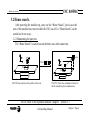
3.4 MANUALLY MOVING THE MACHINE
The axes of the machine can be moved in the following ways:
- [X] [target position]
[Z] [target position]
- continuous movement
- incremental movement
- movement by electronic handwheel
3.4.1
or [Z] [target position]
CONTINUOUS MOVEMENT
Place the left-hand switch in position
and on the right-hand switch select the percentage (0%
to 120%) of the feedrate selected to be applied.
Continuous movement should be done axis to axis. To do this press the JOG
key for the direction of the axis to be moved.
The axis moves with a feedrate equal to the percentage (0% to 120%) of the «F»
feedrate selected.
If during movement the key
is pressed the maximum feedrate possible is carried out, as is
stated in the “G00FEED” axis machine parameter. This feedrate will be applied as long as said key
is pressed, and when released the previous feedrate will be resumed.
Depending on the state of the “LAMCHM” general logic input the movement will be made in the
following way:
* If the PLC sets this mark at a low logic level (0V), the axis will only move while the relevant
JOG
key is pressed.
* If the PLC sets this mark at a high logic level (24V), the axis will start to move when the JOG
key
is pressed and will not stop until said JOG key or another JOG key is pressed
again, and in this case
the movement is transferred to what is indicated by the next
key pressed.
When operating with feedrate "F" in millimeters/revolution the following cases may arise:
a) The spindle is started.
or
The CNC moves the axes to the F programmed.
b) The spindle is stopped but there is a spindle speed S selected.
The CNC calculates the corresponding feedrate in millimeters/minute and moves the axis.
For example, if «F 2.000» and «S 500»:
F (mm/min) = F (rev/min.) x S = 2 x 500 = 1000 mm/min
The axis moves at a feedrate of 1000 in millimeters/minute.
c)
The spindle is stationary and there is no spindle speed S selected.
If feedrate F has value 0, the CNC moves the axes at rapid feedrate.
If feedrate F has any other value, the axes will only be able to be moved if key
and the key for one axis. The CNC moves the axis at fast feedrate.
Chapter 3 - page 8
is pressed
3.
Operating in JOG mode
3.4
Manually moving the machine
3.4.2 Incremental movement
8055MC CNC
3.4.2
INCREMENTAL MOVEMENT
Place the left-hand switch in one of the positions
Incremental movement must be done axis to axis. To do this press the JOG key for the direction of
the axis to be moved.
Each time a key is pressed, the corresponding axis moves the amount set by the switch. This
movement effects the «F» feedrate selected.
Position of the switch
1
10
100
1000
10000
Movement per turn
0.001 mm
0.010 mm
0.100 mm
1.000 mm
10.000 mm
or
or
or
or
or
0.0001
0.0010
0.0100
0.1000
1.0000
inches
inches
inches
inches
inches
Chapter 3 - page 9
3.
Operating in JOG mode
3.4
Manually moving the machine
3.4.3 Movement by means of electronic handwheel
3.4.3
8055MC CNC
MOVEMENT BY MEANS OF ELECTRONIC HANDWHEEL
This option means the machine movements can be governed by means of an electric handwheel.
To do this the left-hand switch has to be located in one of the positions of the handwheel
The positions available are 1, 10 and 100, all of these indicating the multiplication factor applied to
the pulses provided by the electronic handwheel.
Example:
Position of the switch
Movement
1
0.100 mm or
10
1.000 mm or
100
10.000 mm or
per turn
0.0100 inches
0.1000 inches
1.0000 inches
The machine has an electronic handwheel
After selecting the position required on the switch, press one of the JOG keys for the axis which
is to be moved. The axis selected will be displayed in small characters next to the handwheel
symbol at the bottom of the screen.
If a FAGOR electronic handwheel with push button is available, the selection of the axis to be
moved can also be done in the following way:
Press the push button located on the rear of the handwheel. The CNC will select the first of
the axis and display this in highlighted text.
If the push button is pressed again the CNC will select the following axis, making this selection
on a rotative basis.
If the push button is held down for longer than 2 seconds, the CNC will stop selecting said
axis.
After selecting the axis the machine will move this as the handwheel is turned, also respecting
the turning direction applied to the same.
The machine has two or three electronic handwheels
The machine will move each of the axis according to how the corresponding handwheel is turned,
taking into account the position selected on the switch and also respecting the turning direction
applied.
Warning:
It may occur that depending on the turning speed of the handwheel and the
position of the switch, the CNC may be requested to make a movement with a
feedrate higher than the maximum allowed (“G00FEED” axis machine parameter).
The CNC will move the axis the amount required, but limit the feedrate to said
value.
Chapter 3 - page 10
8055MC CNC
3.
Operating in JOG mode
3.4
Manually moving the machine
3.4.4 Feed Handwheel
3.4.4 FEED HANDWHEEL
Usually, when making a part for the first time, the machine feedrate is controlled by means of the
feedrate override switch.
From this version on, it is possible to use the machine handwheels to control that feedrate. This way,
the machining feedrate will depend on how fast the handwheel is turned.
To do this, proceed as follows:
Inhibit all the feedrate override switch positions from the PLC.
Detect how far the handwheel is turned (reading of pulses received)
Set the corresponding feedrate from the PLC depending on the pulses received from the
handwheel.
The following CNC variables return the number of pulses the handwheel has turned.
HANPF shows the number of pulses of the 1st handwheel.
HANPS shows the number of pulses of the 2nd handwheel.
HANPT shows the number of pulses of the 3rd handwheel.
HANPFO shows the number of pulses of the 4th handwheel.
To use this feature, the handwheel must be associated with one of the axes of the machine. General
machine parameters “AXIS1....8” or “HANDWHE1....4” set with values: “21....29”
Example: The machine has a button to activate and deactivate this feature (feed handwheel) and the
feedrate control is carried out with the second handwheel.
CY1
R101=0
reading
END
PRG
DFU I71 = CPL M1000
M1000 = MSG1
NOT M1000
= AND KEYDIS4 $FF800000 KEYDIS4
= JMP L101
If the feature is active
DFU M2009
M2009
= CNCRD(HANPS,R100,M1)
R100
= SBS R101 R100 R102
reading
= MOV R100 R101
= MLS R102 3 R103
= OR KEYDIS4 $7FFFFF KEYDIS4
switch
CPS R103 LT 0 = SBS 0 R103 R103
CPS R103 GT 120 = MOV 120 R103
DFU M2009
M2009
= CNCWR(R103,PLCFRO,M1)
Resets the register containing the previous handwheel
Every time the button is pressed, mark M1000 is inverted
If the feature is active, a message is displayed.
If the feature is not active
enables all the positions of the feedrate override switch
and goes on with program execution
and a leading edge (up flank) occurs at the clock mark
We read the number of handwheel pulses contained in
calculates the number of pulses received from the last
updates R101 for the next reading
calculates in R103 the proper % of feedrate override
inhibits all the other positions of the feedrate override
ignores the handwheel turning direction
Limits the maximum feedrate override to 120%.
With the leading edge (up flank) of the clock mark
set the calculated feedrate override (PLCFRO=R103)
L101
END
Chapter 3 - page 11
3.
Operating in JOG mode
3.4
Manually moving the machine
3.4.5 Master Handwheel
8055MC CNC
3.4.5 MASTER HANDWHEEL
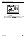
With this feature, it is possible to jog two axes at the same time along a linear or circular path with
a single handwheel.
More handwheels need not be installed on the machine. The one currently installed will be used for
the usual work mode and for this feature (Master Handwheel).
If besides having a general handwheel (general machine parameter AXIS*=11 or 12) other
handwheels are associated with the axes, the CNC assumes the one associated with the X axis (general
machine parameter AXIS*=21) as the Master Handwheel.
This feature must be handled by the PLC.
The PLC activates or deactivates the “master handwheel” mode through logic CNC input
“MASTRHND” M5054,
M5054 = 0 Standard handwheel mode ON.
M5054 = 1 Master handwheel mode
ON.
The PLC must indicate the type of jogging path to follow through logic CNC input “HNLINARC”
M5053,
M5053 = 0 Linear jog
M5053 = 1 Circular jog.
The following example uses the [O2] key to activate and deactivate the “master handwheel”
mode and the [O3] to indicate the type of jog.
DFU B29 R561 = CPL M5054
DFU B31 R561 = CPL M5053
Activate / deactivate the “master handwheel” mode.
Selects the type of jog, linear or circular.
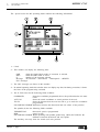
While in handwheel mode and selecting the “master handwheel”, the CNC shows the following data:
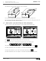
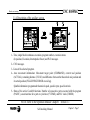
When choosing a linear jog (upper drawing) , the angle of the path must be indicated and when
choosing a circular jog (lower drawing), the arc center coordinates must be indicated.
To define these variables, press the [F] and, then, one of these keys:
Chapter 3 - page 12
3.
3.5
8055MC CNC
3.5
Operating in JOG mode
Tool control
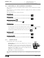
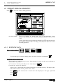
TOOL CONTROL
The standard screen for MC operating mode displays the following information about the tool.
This window displays the following information:
> In large characters, the number "T" of the selected tool.
> The offset number «D» associated with the tool.
> The coordinates for the tool change point.
The CNC does not display this window when text 47 of program 999997 is not defined.
To select any other tool take the following steps:
1st
Press
The CNC will frame the tool number
2nd Enter the tool number to be selected
To exit the selection process press
3rd
Press
key for the CNC to select the new tool.
The CNC will handle the tool change
Chapter 3 - page 13
3.
Operating in JOG mode
3.5
Tool control
3.5.1 Tool change
3.5.1
8055MC CNC
TOOL CHANGE
Depending on the type of tool changer, one can have:
Machine with automatic tool changer
Machine with manual tool changer
In both cases the CNC:
Executes the routine associated with the tool change (general machine P60 «TOOLSUB»).
Sends the PLC all the information required for this to handle the tool change.
And assumes the new values for the tool (offsets, geometry, etc. ...).
An example of how a manual tool changer is handled.
Subroutine 55 as associated with the tools. General machine parameter P60 «TOOLSUB» = 55.
Define the general machine parameter P71 "TAFTERS" = YES so that the tool is selected after
executing the subroutine.
The subroutine associated with the tools can contain the following information:
(SUB 55)
(P100 = NBTOOL)
; Assigns the No. of tool requested to P100
(P101 = MS3)
; If spindle clockwise P101=1
(P102 = MS4)
; If spindle counterclockwise P102=1
G0 G53.... XP?? Y?? ZP?? ; Movement to change point
M5
; Spindle stop
(MSG "SELECT T?P100 - THEN PRESS START")
; Message for requesting tool change
M0
; Program stop and wait until START is pressed
(MSG "" "")
; Erases previous message
(IF P102 EQ 1 GOTO N10)
; Recovers turning direction of spindle
(IF P101 EQ 0 RET)
M3
(RET)
N10 M4
(RET)
After completing the subroutine, the CNC executes function T??, sends the PLC all the
information required for the latter to handle the tool change and assumes the new values for
the tool, (tool offsets, geometry, etc.)
When having a Machining Center, general machine parameter "TOFFM06 (P28) = Yes", the CNC
acts as follows:
If the execution of an operation or cycle involves a tool change, the CNC:
Selects the desired tool in the magazine
Executes the subroutine associated with the tool, general machine parameter "TOOLSUB (P60)"
Executes function M06 to carry out the tool change.
When selecting a new tool in JOG mode or when operating in M mode, the CNC only selects the too
in the magazine and executes the associated subroutine.
The M06 function must be executed by the operator, either by programming an ISO block or by
setting the PLC so it executes the M06 function when pressing a particular key. The following
example uses the [O4] key: DFU B2 R562 = CNCEX1 (M06, M1)
Note: On Machining Centers, the subroutine associated with the tool MUST NOT include the M06.
Chapter 3 - page 14
3.
Operating in JOG mode
3.5
Tool control
3.5.1 Variable tool change point
8055MC CNC
3.5.1.1
VARIABLE TOOL CHANGE POINT
If the manufacturer wishes the user can be allowed to define the tool change point at all times. This
feature logically depends on the type of machine and type of changer.
This feature allows the tool change to be made beside the part, thus avoiding movements to a change
point farther away from the same.
To allow this:
Define text 47 of the program 999997 for the CNC to request the coordinates on X, Y and Z of
the change point.
For example: ;47 $CHANGE POSITION
These coordinates should always refer to machine reference zero (home), for the zero offsets not
to affect the tool change point.
For this reason, the CNC can display, along with coordinates X, Y, Z and in small characters, the
coordinates for the axes referring to home.
For the CNC to show the coordinates of the axes referring to home text 33 of program 999997
has to be defined. For example: ;33 $REFERENCE ZERO (HOME)
Since the tool change point can be modified by the operator at any time, the subroutine associated
with the tools must take these values into account.
Arithmetical parameters P290, P291 and P292 contain the values set by the operator as change
position on X, Y, Z.
Arithmetic parameter P290
Change position on X
Arithmetic parameter P291
Change position on Y
Arithmetic parameter P292
Change position on Z
In subroutine 55 of the previous section, the line fixing the movement to the change point must be
modified:
Where it says: G0 G53 XP??? YP??? ZP???
It should say: G0 G53 XP290 YP291 ZP292
the user.
; Movement to the change point.
; Movement to the change point defined by
Define the coordinates of the change point (X, Y, Z)
Press key
for selecting field «T». Then press key for the relevant axis
or keys:
After moving over the coordinates for the axis to be defined, one can:
a) Enter the value manually. Key in the value required and press the
key
b) Assign the present position of the machine.
Move the axis, by means of the handwheel or the JOG keys, up to the point required.
Press key
The CNC assigns said coordinate to the field selected.
Press key
Chapter 3 - page 15
3.
Operating in JOG mode
3.5
Tool control
3.5.2 Tool calibration
3.5.2
8055MC CNC
TOOL CALIBRATION
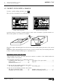
To access tool calibration mode press key
The CNC displays the following information:
1.- Header for the selected operating mode: «Tool calibration».
2.- Help graphics for the tool calibration.
3.- Window for tool calibration.
4.- Current machine status
Actual (real) X, Y, Z coordinates, actual axis feedrate "F", actual spindle speed "S" and
"T" tool currently selected.
5.- Tool number and its Offset number.
6.- Length and offset values set in the tool offset table.
7.- Nominal life, real life, family and status of the table set in the tool table.
To calibrate the tool take the following steps:
1.- Define the tool in the tool table.
2.- Carry out tool calibration
Chapter 3 - page 16
3.
Operating in JOG mode
3.5
Tool control
3.5.2 Tool calibration
8055MC CNC
3.5.2.1
DEFINE THE TOOL IN THE TOOL TABLE
To define a tool in the tool table take the following steps:
Select the tool number to be defined
Press key
to select field «T»
Key in the tool number to be defined and press key
If the tool is defined, the CNC will display the values stored in the table.
If the tool is not defined, the CNC will assign it a offset with the same number and all the data
that define the geometry and lengths of the tool will be reset to value 0.
Select the offset number to be associated with this tool
The "D" field must be selected. If not, use the
keys.
Key in the offset number to be associated with the tool and press
Define the tool dimensions
The tool data is:
R
L
Radius
Length
I
Radius wear
K
Length wear
Even if the tool length is known (L), it is recommended to measure
it as indicated in the next section. Once it has been measured, the
CNC updates the L and K fields.
The CNC assumes (R+I) as the real tool radius and (L+K) as the real tool length.
To set these values, select the corresponding field using the
, key in the desired
value and press
Define the rest of the data associated with the tool
Nominal life. Machining time (in minutes) or number of operations
that the tool may carry out.
Actual life. Machining time already elapsed or number of
operations already carried out.
Family code. Used with automatic tool changer.
0 ... 199. normal tools, 200 ... 255 special tools.
When requesting a worn-out (expired) tool ("actual life" greater than "nominal life"), the CNC
will select the next tool in the table belonging to the same family instead of the one requested.
Tool status. They are 2 fields for internal CNC data. They cannot be modified.
N = Normal (family 0-199)
S = Special (family 200-255)
A = Available
E = Expired (“actual life” greater than “nominal life”)
R = Rejected by the PLC
To define these values, select the corresponding field using the
key in the
desired value and press
Chapter 3 - page 17
3.
Operating in JOG mode
3.5
Tool control
3.5.2.2 Tool measurement
3.5.2.2
8055MC CNC
TOOL MEASUREMENT
There are 2 ways of measuring a tool.
a)
Using a tool calibrating table.
Using the window containing the tool dimensions to set that data.
b) Not using a tool calibrating table. The measurements are carried out with the CNC.
Use the Tool Calibration window.
a) Set the tool length or modify the tool length offsets
This window show the dimensions assigned to the selected tool.
"R" and "L" indicate the tool Radius and Length.
"I" and "K" indicate the offset the CNC has to apply to compensate for tool wear.
The CNC adds the "I" value to the radius "R" and the "K" value to the length "L" for calculating
the real dimensions (R+I) and (L+K) to be used.
Every time the R or L value is defined, the CNC sets the I and K fields, respectively, to zero.
The "I" and "K" values are accumulative. That is, if the "I" value is 0.20 and a value of 0.05
is entered, the CNC assigns a value of 0.25 to the "I" field.
When defining I=0 or K=0, each one of them is reset to "0".
To change one of these values, select the corresponding field , key in the desired value and
press
b) Tool measurement
The window on the right contains the tool dimensions and the one on the lower left-hand side the
data necessary to measure it.
To access the tool calibration window (bottom left) and thus carry out tool calibration, the tool
must be selected on the machine.
Otherwise, press
Chapter 3 - page 18
key in the tool number and press
3.
3.5
3.5.2.2
8055MC CNC
Operating in JOG mode
Tool control
Tool measurement
Select the bottom left window using the
Key in the Z coordinate of the part used for calibration and press
Tool measurement. Length only.
Approach the tool to the part and touch it with it.
Press
The tool is now calibrated. The CNC assigns the length "L" corresponding to it and resets its "K"
field to "0".
The tool radius "R" has to be entered manually.
To calibrate another tool:
Select at the machine:
number
Approach the tool to the part and touch it with it.
Then,
3.5.2.3
MODIFY VALUES WHILE IN EXECUTION
The tool values (dimensions and geometry) may be modified without having to interrupt program
execution.
To do this, press
, the CNC will show the Tool Calibration screen with all the data corresponding
to the active tool being possible to change its data or that of any other tool.
To exit this screen, press
Chapter 3 - page 19
3.
3.6
3.6
Operating in JOG mode
Spindle control
8055MC CNC
SPINDLE CONTROL
The standard MC work mode shows the following information about the spindle.
1.- Actual (real) spindle speed in rpm.
2.- Theoretical spindle speed in rpm.
To select another speed, press
Key in the new value and press
speed.
the CNC highlights the current value
The CNC assumes that value and updates the real spindle
3.- % of the theoretical spindle speed being applied.
To change this percentage, press
4.- Spindle status:
turning clockwise,
turning counterclockwise or
stopped.
To change the spindle status, press:
5.- Currently selected spindle speed range.
When using an automatic tool changer, this value cannot be modified.
and then use the
When NOT using an automatic tool changer, press
current value is highlighted.
Enter the range number to be selected and press
key until the
or
Note: When the machine does not have spindle ranges, this message is useless. That is why the
CNC does not show this message when text number 28 has not be defined in program
999997.
Chapter 3 - page 20
3.
3.7
8055MC CNC
3.7
Operating in JOG mode
Control of external devices
CONTROL OF EXTERNAL DEVICES
The CNC allows up to 6 external devices to be activated and deactivated from the keyboard. One of
these is the cooling fluid.
The activation and deactivation of the devices must be carried out by the machine manufacturer by
means of the PLC program.
The CNC will inform the PLC of the status of each one of the keys. The relevant Register bit will have
value 1 when the key is pressed and value 0 when this is not pressed.
The Register bit for each one of the keys is as follows:
The status of the light for each one of these keys must be controlled by the machine manufacturer
by means of the PLC program, with the MCLED* input variables shown in the figure being available
for this purpose.
Examples:
Control of the coolant:
DFU B28R561 = CPL MCLED1
= CPL O33
Control of the tail-stock (O1). To activate or deactivate the tail-stock a number of conditions must
be satisfied such as spindle stopped, ....
DFU B30R561 AND (Remaining conditions)
= CPL MCLED2
= CPL O34
Chapter 3 - page 21
3.
3.8
Operation in JOG mode
ISO code management
8055MC CNC
3.8 ISO CODE MANAGEMENT
The ISO key gives access to the MDI mode or to the ISO work mode.
To access the MDI mode, the JOG mode must be selected and then press
The CNC displays a window at the bottom of the standard (or special) screen.
In this window, an ISO-coded block may be edited and then executed just like in MDI mode of the
"M model" work mode
once while working with operations or cycles or twice when in
To access the ISO mode, press
the JOG mode.
When accessing the ISO mode, a special screen comes up where up to 6 program blocks may be
edited in ISO code or in high level language.
Example:
[ISO]
G95 G96 S120 M3
G0 Z100
G1 X30 F0.1
Once the desired block or blocks have been edited, press
screen will display the
, The upper right-hand side of the
symbol.
From this moment on, the edited blocks may be simulated, executed or stored like any other operation
or cycle.
Press
to simulate and
to execute.
It is possible to combine blocks edited in ISO code with machining cycles (standard and/or user
defined) to make up part-programs. The chapter on "Program storage" of this manual describes how
to do it and how to operate with them.
To store blocks edited in ISO code, press
Chapter 3 - page 22
4. Working with operations or cycles
8055MC CNC
4. WORKING WITH OPERATIONS OR CYCLES
The following keys of the CNC must be used to select the machining operations or cycles:
When pressing
the CNC shows all the user cycles defined by the machine manufacturer using
the WGDRAW application.
The user cycle is edited like any other standard cycle of the MC mode.
Once all the necessary data has been defined, the operator may Simulate or Execute the cycle
just like any other standard cycle of the MC mode.
When pressing any other key, the CNC selects the corresponding machining operation or cycle
changing the display and lighting up the indicator lamp of the key just pressed.
The operations or cycles that can be selected with each one of these keys are the following:
Boring operation
Surface milling operation
Reaming operation
Pocket cycle with profile
Tapping operation
Rectangular & circular boss
Drilling (2 levels) & center punching
Rectang. (2 levels) & circular pocket
Profile milling operation (2 levels)
Positioning (2 levels)
When the machining operation or cycle has several levels, the
key must be pressed to select
the desired cycle level:
The Boring , Reaming, Tapping, Drilling and Center punching operations may be carried out at the
position occupied by the tool or they could be associated with a positioning by means of
With this CNC, it is possible to combine ISO-coded blocks with standard and/or user-defined
machining operations to create part-programs as described in the chapter on "Part-program storage"
in this manual.
To deselect the cycle and return to the standard display, press the key corresponding to the selected
cycle (the one with the indicator lamp on) or
Note: the operations or cycles can modify global parameters 150 through 299 (both included).
Chapter 4 - page 1
4.
4.1
4.1
Work with operations or cycles
Operation editing mode
8055MC CNC
OPERATION EDITING MODE
Once the operation has been selected, the CNC shows a screen like this:
1.- Name of the selected operation or cycle.
2.- Help graphics.
3.- When referred to positioning, it indicates the associated operation
4.- Current machine status. Coordinates and machining conditions.
5.- Data defining the geometry of the machining operation.
6.- Machining conditions for the operation.
The CNC will highlights an icon, a coordinate or one of the operation (or cycle) defining data.
To select another icon, data or coordinate, one can:
a) Use the
keys, the CNC selects the previous one or the next one.
or
The CNC selects the first coordinate for that axis. By pressing that key
b) Press
again, it will select the next coordinate for that axis.
c) Press
or
The CNC selects the corresponding roughing data . By pressing that key again,
the corresponding finishing data is selected.
d) Press
The CNC selects the "S" roughing data. By pressing that key again, the finishing "S"
data is selected.
Chapter 4 - page 2
8055MC CNC
4.1.1
4.
Work with operations or cycles
4.1
Operation editing mode
4.1.1 Definition of machining conditions
DEFINITION OF THE MACHINING CONDITIONS
Some operations keep the same machining condition during the whole execution process (boring,
reaming, etc.)
Other operations use certain machining conditions for roughing and other conditions for finishing
(pockets, bosses, etc.)
This section describes how to define all this data.
Axis feedrate (F)
Place the cursor over this data, key in the desired value and press
Spindle speed (S)
Place the cursor over this data, key in the desired value and press
Spindle turning direction
Place the cursor over this data and press
Machining tool (T)
Place the cursor over this data, key in the desired value and press
It is also possible to access the Tool calibration mode to check or change the data corresponding
to the selected tool. To do this, place the cursor over the "T" field and press
To quit the tool calibration mode and return to the cycle, press
Roughing pass (∆)
Place the cursor over this data, key in the desired value and press
Finishing stocks (δ, δ z)
Place the cursor over this data, key in the desired value and press
4.1.2
SAFETY PLANE
In all operations, there are four work planes.
Starting plane or tool position when calling the cycle. It does not
have to be defined.
Safety plane. It is used for the first approach and for withdrawing the
tool after the machining operation. It is defined with parameter Zs.
Approach (to the part) plane. It does not have to be defined. The CNC
calculates ti, at 1 mm off the part surface.
Part surface. It is defined with parameter Z.
The tool moves in rapid (G00) to the safety plane (Zs), it keeps on going in rapid to the approach plane
(up to 1mm off the part surface) and, finally, it moves at machining feedrate (G01) down to the part
surface.
Chapter 4 - page 3
4.
4.2
Work with operations or cycles
Simulation and execution of the operation
8055MC CNC
The approach to the part surface depends on the tool position.
If it is above the safety plane (left drawing), it first moves on X and Y and then on Z.
If it is below the safety plane (right drawing), it first moves on Z up to the safety plane, then on X
and Y and finally on Z down to the part surface.
4.2
SIMULATION AND EXECUTION OF THE OPERATION
There are 2 ways to work with operations or cycles: Editing and Execution modes.
Editing mode
Press
Execution mode
to switch from the Editing mode to the Execution mode.
Press one of these keys to switch from the Execution mode to the Editing mode:
The operation or cycle can be simulated in any of the two modes. To do that, press
For further information refer to the chapter on "Execution and Simulation" of this manual.
To execute the operation or cycle, select the Execution mode and press
For further information refer to the chapter on "Execution and Simulation" of this manual.
Chapter 4 - page 4
4.
4.3
8055MC CNC
Work with operations or cycles
Profile milling operation
4.3 PROFILE MILLING OPERATION
Press
to select the profile milling operation
This cycle may be defined in two ways:
Level 1.
One must define:
The starting point (X1, Y1), the intermediate points (P1 through P12), the
end point (Xn, Yn) and the machining conditions in Z (Zs, Z, P, I, Fz)
On the other hand, in the data area for the roughing operation, one must
define whether the milling operation is to be carried out with or without tool
radius compensation.
Level 2.
One must define
The starting point (X, Y), the "Profile Program" number and the machining
conditions in Z (Zs, Z, P, I, Fz)
On the other hand, in the data area for the roughing operation, one must
define whether the milling operation is to be carried out with or without tool
radius compensation.
Chapter 4 - page 5
4.
4.3
Work with operations or cycles
Profile milling operation
8055MC CNC
4.3.1 DEFINING DATA
Coordinates of the starting and end points
These coordinates are defined one at a time. Once the cursor is over the coordinates of the axis
to be defined, one can:
a) Enter the value by hand. Key in the desired value and press
b) Assign the current position of the machine.
Jog the axis, with the handwheel or the JOG keys up to the desired point. The upper righthand window shows the tool position at all times.
Press
window.
for the selected data to assume the value appearing in the upper right-hand
Press
Intermediate points (Level 1)
The intermediate points are defined one at a time. At each point, one must define:
The X, Y coordinates are defined one at a time like those for the starting end points.
The type of corner
To select the type of corner, place the cursor over the icon and press
When not using all 12 definition points, the first unused point must be defined with the same
coordinates as those of the last point of the profile.
Machining conditions in Z (Zs, Z, P, I, Fz)
The machining conditions are defined one by one.
The Zs and Z values are defined like the coordinates of the starting and end points.
To define the rest of the values (P, I, Fz), place the cursor in the corresponding window, key in
the desired value and press
Milling with or without tool radius compensation
Without tool radius compensation
With left-hand tool radius compensation
With right-hand tool radius compensation
To select the type of tool compensation, place the cursor over the icon and press
Chapter 4 - page 6
4.
4.3
8055MC CNC
Work with operations or cycles
Profile milling operation
4.3.2 PROFILE DEFINITION (LEVEL 2)
To define the "Profile program" one can:
Key in the "Profile Program" number directly.
If the "Profile program" number is known, key it in and press
Access the "Profile Program" directory to select one of them
Press
The cycle will show a window with the profile programs already defined.
To move around within a window, use
Place the cursor over the desired program and press
To exit this window without selecting any program, use
Edit a new "Profile program"
To edit a new "Program", key the program number (between 0 and 999) and press
The CNC will display the window for the profile editor (see Operating manual of the 8055 M
CNC, chapter 4 section "Profile Editor").
Once the profile has been edited, the CNC requests a comment to be associated with the "Profile
Program" just edited.
Enter the desired comment and press
If no comment is desired, press
Modify an existing "Profile program".
To modify a "Program", key in its number and press
The CNC will display the profile currently defined in the window for the profile editor.
One can:
Add new elements at the end of the current profile.
Modify the data of any element.
Modify or insert chamfers, roundings, etc.
Delete elements from the element.
An intermediate element of the profile CANNOT be deleted directly. To do it, all the elements
must be deleted one by one starting with the one defined last until reaching to the desired one.
Delete an existing "Profile Program".
Press
the cycle will show the profile programs already defined.
Place the cursor over the "Profile Program" to be deleted and press
The CNC will request confirmation.
Notes:
The profile programs can also be accessed in the "M" mode because the CNC saves them
internally as P 997xxx.
Example: Profile program 123 is internally stored as P997123.
When saving a part-program containing a level-2 profile cycle out to an external device, PC,
floppy disk unit, etc. its associated profile program P997xxx must also be saved.
Chapter 4 - page 7
4.
4.4
Work with operations or cycles
Surface milling operation
8055MC CNC
4.4 SURFACE MILLING OPERATION
Press
to select the surface milling operation.
One must define
The type of milling, the starting point (X1, Y1), the dimensions of the
surface to be milled (L, H, E) and the machining conditions in Z (Zs, Z, P,
I, Fz)
On the other hand, one must define the milling step (∆) in the data area for
the roughing operation and the finishing stock (δz) in the data area for the
finishing operation.
4.4.1 DEFINING DATA
Type of surface milling
To select the type of surface milling, place the cursor over this icon and press
Coordinates of the starting point
These coordinates are defined one by one. After placing the cursor over the axis coordinates to
be defined, it is possible:
a) To enter the value by hand. Key in the value and press
b) Assign the current axis position.
Jog the axis to the desired point with the handwheel or with the JOG keys. The upper righthand window shows the tool position at all times.
Press
window.
Press
Chapter 4 - page 8
for the selected data to assume the value displayed in the upper right-hand
8055MC CNC
4.
4.4
Work with operations or cycles
Surface milling operation
Surface dimensions (L, H, E)
They are defined one by one. Place the cursor in the corresponding window, key in the desired
value and press
When programming parameter «E» with a smaller value than the tool radius, the CNC executes
the planning with an «E» value equal to the tool radius.
Machining conditions in Z (Zs, Z, P, I, Fz)
The machining conditions are defined one by one.
The Zs and Z values are defined like the starting and end points.
To define the rest of the values (P, I, Fz), place the cursor in the corresponding window, key in
the desired value and press
Milling step (∆) and finishing stock (δz)
They are defined one by one. Place the cursor in the corresponding window, key in the desired
value and press
Chapter 4 - page 9
4.
4.5
Work with operations or cycles
Pocket cycle with a profile
8055MC CNC
4.5 POCKET CYCLE WITH A PROFILE
To select a profile milling operation, press
This cycle may be defined in two different ways:
Pocket with 2D profile
Pocket with 3D profile
A pocket consists of contour or outside profile (1) and a series of contours or profiles internal to it.
These inside profiles are referred to as islands.
2D pockets (upper left-hand figure) have all the walls of the outside profile plus those of the vertical
islands.
3D pockets (upper right-hand figure) may have one, several or all the walls of the outside profile and/
or those of the non-vertical islands (up to a maximum of 4).
Programming pockets with 2D profiles
When defining the Profile, one must specify the contour or contours of the islands besides the
outside contour of the pocket.
The machining operation in Z is defined by means of :
Coordinate of the safety plane ............... Zs
Coordinate of the part surface .................... Z
Pocket depth ............................................... P
Step in Z ......................................................... I
Penetration feedrate in Z ......................... Fz
In the area for the roughing operation data, define:
The lateral penetration angle ....................β
The milling pass ........................................... ∆
In the area for the finishing operation data, define:
The lateral penetration angle ....................θ
Finishing stock on the walls ....................... δ
Finishing stock at the bottom ................. δz
Number of finishing passes in Z ............... N
Chapter 4 - page 10
4.
4.5
8055MC CNC
Work with operations or cycles
Pocket cycle with a profile
Programming pockets with 3D profiles
Pocket ID number. (3D POCKET)
It is possible to have several 3D pockets. The CNC associates with each 3D pocket all its data
(surface profile, depth profile, machining conditions, etc.)
Surface profile or profile in the X,Y plane. Profile (P. XY).
It must indicate the contour or contours of the possible islands besides the outside contour of the
pocket.
Depth profile corresponding to the profile defined first. Profile (P. Z1)
It usually corresponds to the outside contour of the pocket.
Depth profile corresponding to the profile defined second . Profile (P. Z2)
It usually corresponds to the contour of the island defined first.
Depth profile corresponding to the profile defined third. Profile (P. Z3)
It usually corresponds to the contour of the island defined second.
Depth profile corresponding to the profile defined fourth. Profile (P. Z4)
It usually corresponds to the contour of the island defined third.
Once all the profiles have been defined, the 3D pocket configuration must be validated. To do so,
place the cursor over the
The cycle will show the
icon and press
icon.
The machining operation in Z is defined by means of:
The coordinate of the safety plane ........ Zs
Coordinate of the part surface .................... Z
Pocket depth ...............................................P
Roughing pass in Z ..................................... I1
Penetration feedrate in Z ......................... Fz
Semi-finishing pass in Z ............................. I2
In the area for roughing data, the following must be defined:
Lateral penetration angle ..........................β
Milling pass .................................................. ∆
In the area for finishing data, the following must be defined:
Tool tip radius ........................................... R
Finishing stock on walls .............................. δ
Finishing pass ......................................... (ε)
Direction of the finishing passes on the walls
Notes:
The pocket configuration program and the profile programs can also be accessed in the
"M" mode since the CNC stores them internally as:
P995xxx 3D pocket configuration
P998xxx The XY plane profiles in 2D and 3D pockets
P996xxx Depth profiles in 3D pockets
Chapter 4 - page 11
4.
4.5
Work with operations or cycles
Pocket cycle with a profile
8055MC CNC
4.5.1 DATA DEFINITION
Machining conditions in Z (Zs, Z, P, Fz, I, I1, I2)
The machining conditions must be defined one by one.
To define the values (P, Fz, I, I1, I2), place the cursor in the corresponding window, key in the
desired value and press
To define the values (Zs and Z), after placing the cursor in the corresponding window, one may:
a) Enter the value by hand. Key in the desired value and press
b) Assign the current axis position.
Jog the axis to the desired point with the handwheel or the JOG keys. The upper right-hand
window shows the tool position at all times.
Press
for the selected data to assume the value shown in the upper right-hand window.
Press
Milling pass (∆) and finishing passes (ε )
Place the cursor in the corresponding window, roughing or finishing operation, key in the desired
value and press
Lateral penetration angles (β, θ)
Place the cursor in the corresponding window, roughing or finishing operation, key in the desired
value and press
Finishing stocks: on the walls (δ) and at the bottom (δz)
Place the cursor in the corresponding window, finishing operation, key in the desired value and
press
Finishing tool tip radius (R)
Place the cursor in the corresponding window, finishing operation, key in the desired value and
press
Direction of the finishing passes on the walls
To select the direction of the finishing passes on the walls,
place the cursor over this icon and press
Chapter 4 - page 12
4.
4.5
8055MC CNC
Work with operations or cycles
Pocket cycle with a profile
4.5.2 PROFILE DEFINITION
To define a Profile, after selecting the corresponding window, one can:
Key in the "Profile Program" number directly.
If the "Profile program" number is known, key it in and press
Access the "Profile Program" directory to select one of them
Press
The cycle will show a window with the profile programs already defined. There are
3 directories, one for the pocket configuration profiles, another one for the XY plane profile and
a third one for the depth profile of the pocket.
To move around within a window, use
Place the cursor over the desired program and press
To exit this window without selecting any program, use
Edit a new "Profile program"
To edit a new "Program", key the program number (between 0 and 999) and press
The CNC will display the window for the profile editor (see Operating manual of the 8055 M
CNC, chapter 4 section "Profile Editor").
Once the profile has been edited, the CNC requests a comment to be associated with the "Profile
Program" just edited.
Enter the desired comment and press
If no comment is desired, press
Modify an existing "Profile program".
To modify a "Program", key in its number and press
The CNC will display the profile currently defined in the window for the profile editor.
One can:
Add new elements at the end of the current profile.
Modify the data of any element.
Modify or insert chamfers, roundings, etc.
Delete elements from the element.
An intermediate element of the profile CANNOT be deleted directly. To do it, all the elements
must be deleted one by one starting with the one defined last until reaching to the desired one.
Delete an existing "Profile Program".
Press
the cycle will show the profile programs already defined.
Place the cursor over the "Profile Program" to be deleted and press
The CNC will request confirmation.
Notes:
Profile programs can also be accessed in the "M" mode since the CNC stores them internally
as:
P995xxx The 3D configuration profiles
P998xxx The XY plane profiles in 2D and 3D pockets.
P996xxx The depth profiles of 3D pockets
When saving a part-program containing a pocket cycle with profile out to an external
device, PC, floppy disk unit, etc. its associated profile programs must also be saved.
Chapter 4 - page 13
4.
4.5
Work with operations or cycles
Pocket cycle with a profile
8055MC CNC
4.5.3 EXAMPLES OF PROFILE DEFINITION
Example of how to define a 2D pocket without islands:
2D Pocket Profile 1 Recall
Configuration
Abscissa axis: X
Ordinate axis: Y
Autozoom: Yes
Validate
Profile
Starting Point
X 20
Y -8
Validate
Straight
X 20
Y -40
Validate
Straight
X 145 Y -40
Validate
Straight
X 145 Y -25
Validate
Clockwise arc
Xf 145 Yf 25
R 25 Validate
Straight
X 145 Y 40
Validate
Straight
X 20
Y 40
Validate
Straight
X 20
Y8
Validate
Straight
X 55
Y8
Validate
Straight
X 55
Y -8
Validate
Straight
X 20
Y -8
Validate
Corners Chamfer
Select lower left-hand corner
Enter Chamfer 15 Enter
Select upper left-hand corner
Enter Chamfer 15 Enter
Escape
Finish
Save Profile
Example of how to define a 2D profile with islands:
2D Pocket Profile 2 Recall
Configuration
Abscissa axis: X
Ordinate axis: Y
Autozoom: Yes
Validate
Profile (outside profile)
Starting Point
X 20
Y0
Validate
Straight
X 20
Y -40
Validate
Straight
X 145 Y -40
Validate
Straight
X 145 Y 40
Validate
Straight
X 20
Y 40
Validate
Straight
X 20
Y0
Validate
Corner
Chamfer
Select lower left-hand corner
Enter
Chamfer 15
Enter
Select lower right-hand corner
Enter
Chamfer 15
Enter
Select upper right-hand corner
Enter
Chamfer 15
Enter
Select upper left-hand corner
Enter
Chamfer 15
Enter
Escape
New Profile (island)
Profile
Starting Point
X 115 Y -25
Validate
Straight
X 115 Y 0
Validate
Clockwise arc
Xf 90 Yf 25
Xc 115
Straight
X 50
Y 25
Validate
Straight
X 50
Y0
Validate
Clockwise arc
Xf 75 Yf -25
Xc 50
Straight
X 115 Y -25
Validate
Finish
Save Profile
Chapter 4 - page 14
Yc 25
R 25 Validate
Yc -25
R 25 Validate
4.
4.5
8055MC CNC
Work with operations or cycles
Pocket cycle with a profile
Example of how to define a 3D pocket without islands:
3D Pocket= 1
P.XY= 3 Recall
Configuration
Abscissa axis: X
Ordinate
Autozoom: Yes
Validate
Profile (outside profile)
Starting Point
X 20
Y0
Straight
X 20
Y -40
Straight
X 145 Y -40
Straight
X 145 Y 40
Straight
X 20
Y 40
Straight
X 20
Y0
Finish
Save Profile
axis: Y
Validate
Validate
Validate
Validate
Validate
Validate
P.Z1= 1 Recall
Configuration
Abscissa axis: X
Ordinate axis: Z
Autozoom: Yes
Validate
Profile (depth profile)
Starting Point
X 20
Z0
Validate
Straight
X 30
Z -20
Validate
Finish
Save Profile
Example of how to define a 3D pocket with islands:
3D Pocket= 2
P.XY= 4 Recall
Configuration
Abscissa axis: X
Ordinate axis: Y
Autozoom: Yes
Validate
Profile (outside profile)
Starting Point
X 20
Y0
Validate
Straight
X 20
Y -40
Validate
Straight
X 145 Y -40
Validate
Straight
X 145 Y 40
Validate
Straight
X 20
Y 40
Validate
Straight
X 20
Y0
Validate
New Profile (island)
Circle
X 62.5 Y0 Xc 82.5 Yc 0 Validate
Finish
Save Profile
P.Z1= 2 Recall
Configuration
Abscissa axis: X
Ordinate axis: Z
Autozoom: Yes
Validate
Profile (outside depth profile)
Starting Point
X 20
Z0
Validate
Straight
X 30
Z -20
Validate
Finish
Save Profile
P.Z2= 3 Recall
Configuration
Abscissa axis: X
Ordinate axis: Z
Autozoom: Yes
Profile (depth profile of the island)
Starting Point
X 77,5 Z 0
Validate
Straight
X 62,5 Z -20
Validate
Finish
Save Profile
Validate
Chapter 4 - page 15
4.
4.6
Work with operations or cycles
Rectangular and Circular Boss cycles
8055MC CNC
4.6 RECTANGULAR AND CIRCULAR BOSS CYCLES
To select the boss cycles, press
Rectangular Boss cycle
One must define
The starting point (X,Y), the dimensions of the boss (L,H), the inclination
angle (α), the amount of material to be removed (Q), the type of corner and
the machining conditions in Z (Zs, Z, P, I, Fz)
In the roughing area, define the milling step ( ∆) and the machining
direction
In the finishing area, define the finishing stocks (δ and
finishing passes and the machining direction
δz), the number of
Circular boss cycle
One must define
The center coordinates (Xc, Yc), the boss radius (R), the amount of material
to be removed (Q) and the machining conditions in Z (Zs, Z, P, I, Fz)
In the roughing area, define the milling step ( ∆) and the machining
direction
In the finishing area, define the finishing stocks (δ and
finishing passes and the machining direction
Chapter 4 - page 16
δz), the number of
4.
4.6
8055MC CNC
Work with operations or cycles
Rectangular and Circular Boss cycles
4.6.1 DATA DEFINITION
Coordinates of the starting point
These coordinates are defined one by one. After placing the cursor over the axis coordinates, one
can:
a) Enter the value by hand. Key in the desired value and press
b) Assign the position of the axis.
Jog the axis to the desired point with the handwheel or the JOG keys. The upper right-hand
window shows the tool position at all times.
Press
window.
for the selected data to assume the value appearing in the upper right-hand
Press
Rectangular Boss: Dimensions, inclination angle and material to be removed
They are defined one by one. Place the cursor in the corresponding window, key in the desired
value and press
Type of corner
To select the type of corner, place the cursor over this icon and press
Circular: Center coordinates, radius and material to be removed
They are defined one by one.
The center coordinates (Xc, Yc) are defined like the starting and end points.
To define the rest of the values (R, Q) place the cursor in the corresponding window, key in the
desired value and press
Machining conditions in Z (Zs, Z, P, I, Fz)
They are defined one by one.
The Zs and Z values are defined like the starting and end points.
To define the rest of the values (P, I, Fz), place the desired value and press
Milling pass (∆)
Finishing stocks: on the walls (δ) and at the bottom (δz)
Number of finishing passes (N)
Place the cursor in the window for the finishing operation, key in the desired value and press
Chapter 4 - page 17
4.
4.7
Work with operations or cycles
Rectangular (2 levels) and Circular Pocket cycles
8055MC CNC
4.7 RECTANGULAR (2 LEVELS) AND CIRCULAR POCKET CYCLES
To select these cycles press
Rectangular pocket cycle (Level 1)
One must define The starting point (X, Y), the pocket dimensions (L, H) and the machining
conditions in Z (Zs, Z, P, I, Fz)
One must also define the milling pass (∆), the finishing stock (δ) and the
machining direction
Rectangular pocket cycle (Level 2)
One must define
The starting point (X, Y), the dimensions of the pocket (L, H), the
inclination angle (α), the type of corner and the machining conditions in
Z (Zs, Z, P, I, Fz)
In the area for roughing data, define the lateral penetration angle (β), the
milling pass (∆) and the machining direction
In the area for finishing data, define the lateral penetration angle (θ), the
finishing stocks (δ and δz), the number of finishing passes (N) and the
machining direction
Chapter 4 - page 18
4.
4.7
8055MC CNC
Work with operations or cycles
Rectangular (2 levels) and Circular Pocket cycles
Circular pocket cycle
One must define
The center coordinates (Xc, Yc), the boss radius (R) and the machining
conditions in Z (Zs, Z, P, I, Fz)
In the area for roughing data, define the lateral penetration angle (β), the
milling pass (∆) and the machining direction
In the area for finishing data, define the lateral penetration angle (θ), the
finishing stocks (δ and δz), the number of finishing passes (N) and the
machining direction
4.7.1 DATA DEFINITION
Coordinates of the starting point
The coordinates are defined one by one. After placing the cursor over the axis coordinates to be
defined, one can:
a) Enter the value by hand. Key in the desired value and press
b) Assign the current axis position.
Jog the axis to the desired point with the handwheel or the JOG keys. The upper right-hand
window shows the tool position at all times.
Press
window.
for the selected data to assume the value appearing in the upper right-hand
Press
Rectangular Pocket: Dimensions and inclination angle
They are defined one by one. Place the cursor in the corresponding window, key in the desired
value and press
Chapter 4 - page 19
4.
4.7
Work with operations or cycles
Rectangular (2 levels) and Circular Pocket cycles
8055MC CNC
Type of corner
To select the type of corner, place the cursor over this icon and press
If, due to the dimensions of the pocket, the specified rounding or chamfer is not possible, the
CNC will make a chamfer or rounding with the largest possible value.
Circular pocket: Center coordinates and radius
They are defined one by one.
The center coordinates (Xc, Yc), are defined like the starting and end point.
To define the radius (R), place the cursor in the corresponding window, key in the desired value
and press
Machining conditions in Z (Zs, Z, P, I, Fz)
They are defined one by one.
The Zs and Z values are defined like the starting and end point.
To define the rest of the values (P, I, Fz), place the cursor in the corresponding window, key in
the desired value and press
Milling pass (∆)
Finishing stocks: on walls (δ) and at the bottom (δz)
Number of finishing passes (N)
Place the cursor in the window for finishing operation, key in the desired value and press
Lateral penetration angle (β, θ)
In the rectangular pocket, the penetration is carried out from the center of the pocket out and
following the first machining path. The passes are carried out as often as needed and the
operation always concludes at the center of the pocket.
In the circular pocket, the penetration is carried out from the center of the pocket following
a helical path with a radius equal to the that of the tool while keeping the machining
direction. The penetration always ends at the center of the pocket.
Place the cursor in the corresponding window, roughing or finishing operation, key in the desired
value and press
Chapter 4 - page 20
4.
4.8
CNC 8055MC
Work with operations or cycles
Positioning (2 levels)
4.8 POSITIONING (2 LEVELS)
To select the positioning cycle, press
This cycle may be defined in two different ways:
Level 1.
One must define
The target point (X, Y, Z), the axes movement sequence and the type of
feedrate
Level 2.
One must define
The target point (X, Y, Z), the axes moving sequence, the type of feedrate
and the auxiliary functions "M" to be executed before and after the
movement.
Chapter 4 - page 21
4.
4.8
Work with operations or cycles
Positioning (2 levels)
CNC 8055MC
4.8.1 DATA DEFINITION
Coordinates of the target point
These coordinates are defined one by one. After placing the cursor over the axis coordinates, on
can:
a) Enter the value by hand. Key in the desired value and press
b) Assign the current axis position.
Jog the axis to the desired point with the handwheel or the JOG keys. The upper right-hand
window shows the tool position at all times.
Press
window.
for the selected data to assume the value appearing in the upper right-hand
Press
Axes moving sequence
All three axes at the same time
First the Z axis and then in the plane (X and Y axis at the same time)
Firs in the plane (X and Y at the same time) and then the Z axis
To select the moving sequence, place the cursor over this icon and press
Type of axis feedrate
Programmed feedrate
Rapid feed
To select the type of feedrate, place the cursor over this icon and press
Auxiliary "M" functions
Select the corresponding window with
Use
to move around inside the window
The functions will be executed in the same order as inserted in the list.
To delete a function, select it and press
Chapter 4 - page 22
4.
4.9
CNC 8055MC
Work with operations or cycles
Boring operation
4.9 BORING OPERATION
To select the boring operation, press
One must define
The machining point (X, Y), the coordinate of the safety plane (Zs), the
coordinate of the part surface (Z), The total machining depth (P) and the
dwell at the bottom (t)
The Boring operation may be carried out in the indicated position (X,Y) or a positioning may
be associated with it by means of the
keys as described later on.
4.9.1 DATA DEFINITION
Coordinates of the machining point
These coordinates are defined one by one. After placing the cursor over the axis coordinates, one
can:
a) Enter the value by hand. Key in the desired value and press
b) Assign the current axis position.
Jog the axis to the desired point with the handwheel or the JOG keys. The upper right-hand
window shows the tool position at all times.
Press
window.
for the selected data to assume the value appearing in the upper right-hand
Press
Machining conditions in Z (Zs, Z, P, t)
The machining conditions are defined one by one.
The Zs and Z values are defined like those of the machining point.
To define the rest of the values (P, t), place the cursor in the corresponding window, key in the
desired value and press
Chapter 4 - page 23
4.
4.10
Work with operations or cycles
Reaming operation
CNC 8055MC
4.10 REAMING OPERATION
To select the Reaming operation, press
One must define
The machining point (X, Y), the coordinate of the safety plane (Zs), the
coordinate of the part surface (Z), the total machining depth (P) and the
dwell at the bottom (t)
The Reaming operation can be carried out in the indicated position (X,Y) or a positioning may
be associated with it by means of the
keys as described later on.
4.10.1 DATA DEFINITION
Coordinates of the machining point
These coordinates are defined one by one. After placing the cursor over the axis coordinates, one
can:
a) Enter the value by hand. Key in the desired value and press
b) Assign the current axis position.
Jog the axis to the desired point with the handwheel or the JOG keys. The upper right-hand
window shows the tool position at all times.
Press
window.
for the selected data to assume the value appearing in the upper right-hand
Press
Machining conditions in Z (Zs, Z, P, t)
The machining conditions are defined one by one.
The Zs and Z values are defined like those of the machining point.
To define the rest of the values (P, t), place the cursor in the corresponding window, key in the
desired value and press
Chapter 4 - page 24
4.
4.11
CNC 8055MC
Work with operations or cycles
Tapping operation
4.11 TAPPING OPERATION
To select the tapping operation, press
One must define
The machining point (X, Y), the coordinate of the safety plane (Zs), the
coordinate of the part surface (Z), the total machining depth (P) and the
dwell at the bottom (t) and the type of Tapping.
The Tapping operation can be carried out in the indicated position (X,Y) or a positioning may
be associated with it by means of the
keys as described later on.
Chapter 4 - page 25
4.
4.11
Work with operations or cycles
Tapping operation
CNC 8055MC
4.11.1 DATA DEFINITION
Coordinates of the machining point
These coordinates are defined one by one. After placing the cursor over the axis coordinates, one
can:
a) Enter the value by hand. Key in the desired value and press
b) Assign the current axis position.
Jog the axis to the desired point with the handwheel or the JOG keys. The upper right-hand
window shows the tool position at all times.
Press
window.
for the selected data to assume the value appearing in the upper right-hand
Press
Machining conditions in Z (Zs, Z, P, t)
The machining conditions are defined one by one.
The Zs and Z values are defined like those of the machining point.
To define the rest of the values (P, t), place the cursor in the corresponding window, key in the
desired value and press
Type of tapping
Rigid tapping .................. Without clutch
Regular tapping .............. With a clutch
To select the type of tapping, place the cursor over this icon and press
Chapter 4 - page 26
4.
4.12
CNC 8055MC
Work with operations or cycles
Drilling (2 levels) and Center Punching operations
4.12 DRILLING (2 LEVELS) AND CENTER PUNCHING OPERATIONS
To select the Drilling and Center Punching operations, press
Center punching operation
One must define
The punch point (X, Y), the coordinate of the safety plane (Zs), the
coordinate of the part surface (Z), the total machining depth (P) and the
dwell at the bottom (t) and the type of center punching.
The center punching operation can be carried out in the indicated position (X,Y) or a positioning
may be associated with it by means of the
keys as described later on.
Drilling operation. Level 1
One must define
The drilling point (X, Y), the coordinate of the safety plane (Zs), the
coordinate of the part surface (Z), the total machining depth (P), the drilling
peck and the dwell at the bottom (t).
The drilling operation can be carried out in the indicated position (X,Y) or a positioning may be
associated with it by means of the
keys as described later on.
Chapter 4 - page 27
4.
4.12
Work with operations or cycles
Drilling (2 levels) and Center Punching operations
CNC 8055MC
Drilling operation. Level 2
One must define
The machining point (X, Y), the coordinate of the safety plane (Zs), the
coordinate of the part surface (Z), the total machining depth (P), the drilling
peck (I), the dwell at the bottom (t) and the withdrawal distance after each
penetration (B)
The Drilling operation may be carried out in the indicated position (X,Y) or may be associated
with a positioning using the
Chapter 4 - page 28
keys as described later on.
4.
4.12
CNC 8055MC
Work with operations or cycles
Drilling (2 levels) and Center Punching operations
4.12.1 DATA DEFINITION
Coordinates of the machining point
These coordinates are defined one by one. After placing the cursor over the axis coordinates, one
can:
a) Enter the value by hand. Key in the desired value and press
b) Assign the current axis position.
Jog the axis to the desired point with the handwheel or the JOG keys. The upper right-hand
window shows the tool position at all times.
Press
window.
for the selected data to assume the value appearing in the upper right-hand
Press
Machining conditions in Z (Zs, Z, P, I, t, B)
The machining conditions are defined one by one.
The Zs and Z values are defined like the coordinates of the machining point.
To define the rest of the values (P, I, t, B), place the cursor in the corresponding window, key
in the desired value and press
One must define
The machining point (X, Y), the machining conditions in Z (Zs, Z, t) and
the type of center punching.
Type of center punching
The type of center punching may be defined in two ways:
a) By defining the total machining depth (P)
b) By defining the punch angle (α) and the diameter of the point (Φ)
To select the type of center punching, place the cursor over this icon and press
To define the "P, α, Φ" values, place the cursor in the corresponding window, key in the desired
value and press
Chapter 4 - page 29
4.
4.13
Work with operations and cycles
Multiple positioning
4.13
CNC 8055MC
MULTIPLE POSITIONING
With this CNC, it is possible to associate multiple positioning with Boring, Reaming, Tapping,
Drilling and Center Punching operations.
The following keys of the "8055 MC" CNC must be used to select this feature.
When pressing one of these keys, the CNC selects the corresponding type of positioning and it
changes the display.
It keeps the lamp ON of the key corresponding to the selected operation (Boring, Reaming, etc.) and
the bottom of the screen shows the data for that operation.
The types of multiple positioning that can be selected with each key are
At random points
In a straight line
In a bolt-hole pattern
In a parallelogram pattern
In a grid pattern
Chapter 4 - page 30
4.
Work with operations and cycles
4.13 Multiple positioning
4.13.1 Multiple positioning at ramdom points
CNC 8055MC
4.13.1
MULTIPLE POSITIONING AT RANDOM POINTS
To associate this positioning with an operation, press
Up to 12 points can be defined. Coordinates (X1, Y1) .... (X12, Y12)
When not using all 12 points, the first unused point must be defined with the same coordinates
as those of the last point.
Point definition
The coordinates are defined one by one. After placing the cursor over the axis coordinates, one
can:
a) Enter the value by hand. Key in the desired value and press
b) Assign the current axis position.
Jog the axis to the desired point with the handwheel or the JOG keys. The upper right-hand
window shows the tool position at all times.
Press
for the selected data to assume the value shown in the upper right-hand window.
Press
Chapter 4 - page 31
4.
Work with operations and cycles
4.13 Multiple positioning
4.13.2 Multiple positioning in a straight line
CNC 8055MC
4.13.2 MULTIPLE POSITIONING IN A STRAIGHT LINE
To associate this positioning with an operation, press
This may be defined in 5 different ways:
1)
The coordinates of the first point ........................................ (X1, Y1)
The coordinates of the last point ......................................... (Xn, Yn)
Distance between points ................................................................. (I)
2)
The coordinates of the first point ........................................ (X1, Y1)
The coordinates of the last point ......................................... (Xn, Yn)
Number of points ............................................................................ (N)
3)
The coordinates of the first point ........................................ (X1, Y1)
The inclination angle ..................................................................... ( α)
Total distance from first to last point ............................................ (L)
Distance between points ................................................................. (I)
4)
The coordinates of the first point ........................................ (X1, Y1)
The inclination angle ..................................................................... ( α)
Total distance from first to last point ............................................ (L)
Number of points ............................................................................ (N)
5)
The coordinates of the first point ........................................ (X1, Y1)
The inclination angle ..................................................................... ( α)
Number of points ............................................................................ (N)
Distance between points ................................................................. (I)
To select the desired one, place the cursor over the
Point definition
Chapter 4 - page 32
icon and press
4.
Work with operations and cycles
4.13 Multiple positioning
4.13.2 Multiple positioning in a straight line
CNC 8055MC
The coordinates are defined one by one. After placing the cursor over the axis coordinates, one
can:
a) Enter the value by hand. Key in the desired value and press
b) Assign the current axis position.
Jog the axis to the desired point with the handwheel or the JOG keys. The upper right-hand
window shows the tool position at all times.
Press
for the selected data to assume the value shown in the upper right-hand window.
Press
To define the rest of the values (I, N,
α, L), place the cursor in the corresponding window, key
in the desired value and press
Chapter 4 - page 33
4.
Work with operations and cycles
4.13 Multiple positioning
4.13.3 Multiple positioning in a bolt-hole pattern
CNC 8055MC
4.13.3 MULTIPLE POSITIONING IN AN ARC (BOLT-HOLE PATTERN)
To associate this positioning with an operation, press
This could be defined in 6 different ways:
1)
The
The
The
The
coordinates of the first point ........................................ (X1, Y1)
center coordinates .......................................................... (Xc, Yc)
angle of the last point .............................................................. (τ)
angular distance between points ............................................ (β)
2)
The
The
The
The
The
coordinates of the first point ........................................ (X1, Y1)
radius ........................................................................................ (R)
angle of the first point ............................................................. (α)
angle of the last point .............................................................. (τ)
angular distance between points ............................................ (β)
3)
The
The
The
The
coordinates of the first point ........................................ (X1, Y1)
center coordinates .......................................................... (Xc, Yc)
number of points ..................................................................... (N)
angle of the last point .............................................................. (τ)
4)
The
The
The
The
coordinates of the first point ........................................ (X1, Y1)
center coordinates .......................................................... (Xc, Yc)
number of points ..................................................................... (N)
angular distance between points ............................................ (β)
5)
The
The
The
The
The
coordinates of the first point ........................................ (X1, Y1)
radius ........................................................................................ (R)
angle of the first point ............................................................. (α)
number of points ..................................................................... (N)
angle of the last point .............................................................. (τ)
6)
The
The
The
The
The
coordinates of the first point ........................................ (X1, Y1)
radius ........................................................................................ (R)
angle of the first point ............................................................. (α)
number of points ..................................................................... (N)
angular distance between points ............................................ (β)
To select the desired one, place the cursor over the
Chapter 4 - page 34
icon and press
4.
Work with operations and cycles
4.13 Multiple positioning
4.13.3 Multiple positioning in a bolt-hole pattern
CNC 8055MC
Point definition
The coordinates are defined one by one. After placing the cursor over the axis coordinates, one
can:
a) Enter the value by hand. Key in the desired value and press
b) Assign the current axis position.
Jog the axis to the desired point with the handwheel or the JOG keys. The upper right-hand
window shows the tool position at all times.
Press
for the selected data to assume the value shown in the upper right-hand window.
Press
To define the rest of the values (R, N, α, β, τ), place the cursor in the corresponding window,
key in the desired value and press
Chapter 4 - page 35
4.
Work with operations and cycles
4.13 Multiple positioning
4.13.4 Multiple positioning in a parallelogram pattern
CNC 8055MC
4.13.4 MULTIPLE POSITIONING IN A PARALLELOGRAM PATTERN
To associate this positioning with an operation, press
This could be defined in 3 different ways:
1)
The
The
The
The
The
coordinates of the first point ........................................ (X1, Y1)
lengths in X, Y ............................................................... (Lx, Ly)
X and Y distances between points ................................. (Ix, Iy)
rotation angle ........................................................................... (α)
angle between the sides ........................................................... (β)
2)
The
The
The
The
The
coordinates of the first point ........................................ (X1, Y1)
lengths in X and Y ......................................................... (Lx, Ly)
number of points in X and Y ....................................... (Nx, Ny)
rotation angle ........................................................................... (α)
angle between the sides ........................................................... (β)
3)
The
The
The
The
The
coordinates of the first point ........................................ (X1, Y1)
X and Y distances between points ................................. (Ix, Iy)
number of points in X and Y ....................................... (Nx, Ny)
rotation angle ........................................................................... (α)
rotation angle ............................................................................(β)
To select the desired one, place the cursor over the
icon and press
Point definition
The coordinates are defined one by one. After placing the cursor over the axis coordinates, one
can:
a) Enter the value by hand. Key in the desired value and press
b) Assign the current axis position.
Jog the axis to the desired point with the handwheel or the JOG keys. The upper right-hand
window shows the tool position at all times.
Press
for the selected data to assume the value shown in the upper right-hand window.
Press
To define the rest of the values (Lx, Ly, Ix, Iy, α, β, Nx, Ny), place the cursor in the corresponding
window, key in the desired value and press
Chapter 4 - page 36
44.
Work with operations and cycles
4.13 Multiple positioning
4.13.5 Multiple positioning in a grid pattern
CNC 8055MC
4.13.5 MULTIPLE POSITIONING IN A GRID PATTERN
To associate this positioning with an operation, press
This could be defined in 3 different ways:
1)
The
The
The
The
The
coordinates of the first point ........................................ (X1, Y1)
lengths in X, Y ............................................................... (Lx, Ly)
X and Y distances between points ................................. (Ix, Iy)
rotation angle ........................................................................... ( α)
angle between the sides ...........................................................(β)
2)
The
The
The
The
The
coordinates of the first point ........................................ (X1, Y1)
lengths in X and Y ......................................................... (Lx, Ly)
number of points in X and Y ....................................... (Nx, Ny)
rotation angle ........................................................................... ( α)
angle between the sides ...........................................................(β)
3)
The
The
The
The
The
coordinates of the first point ........................................ (X1, Y1)
X and Y distances between points ................................. (Ix, Iy)
number of points in X and Y ....................................... (Nx, Ny)
rotation angle ........................................................................... ( α)
rotation angle ............................................................................(β)
To select the desired one, place the cursor over the
icon and press
Point definition
The coordinates are defined one by one. After placing the cursor over the axis coordinates, one
can:
a) Enter the value by hand. Key in the desired value and press
b) Assign the current axis position.
Jog the axis to the desired point with the handwheel or the JOG keys. The upper right-hand
window shows the tool position at all times.
Press
for the selected data to assume the value shown in the upper right-hand window.
Press
To define the rest of the values (Lx, Ly, Ix, Iy, α, β, Nx, Ny), place the cursor in the corresponding
window, key in the desired value and press
Chapter 4 - page 37
5.
8055MC CNC
Storage of programs
5. STORAGE OF PROGRAMS
This CNC allows the editing, simulating and executing of part-programs.
Each of these programs consists of the interlinking of elementary operations or cycles and/or blocks
edited in ISO code. The form of editing or defining said operations or cycles is explained in the
previous chapter.
This chapter explains how to operate with these part-programs and has the following sections and
subsections for this purpose.
List of programs stored
See the content of a program ......................... See one of the operations in detail
Edit a new part-program......................... ...... Storage of an operation or cycle
Erase a part-program
Copy one part-program in another
Modify a part-program .................................... Erase an operation
Move an operation to another position
Add or insert to a new operation
Modify an already existing operation
Chapter 5 - page 1
5.
5.1
5.1
Storage of programs
List of stored programs
8055MC CNC
LIST OF STORED PROGRAMS
To access the list of part-programs stored press
Note: If the «Tool Calibration» mode is selected you cannot directly access the list of part-programs. This
mode must first be left, that is, press
and then
.
The CNC will display the following information:
On the left there is a list of part-programs that are stored in the CNC’s memory.
and
to move
When there are more programs than those displayed in the window, use keys
the pointer over the list of programs. To go forward or backward page by page use the following
combinations of keys
and
.
The right-hand column will display the cycles and/or ISO-coded blocks that said part consists of.
After selecting the program list, the CNC will let you:
Create a new part-program
See the content of a part-program
Erase a part-program
Copy a part-program in another
Modify a part-program
To leave the directory or list of part-programs press:
the key for an operation
or
Chapter 5 - page 2
5.
Storage of programs
5.2
See content of a program
5.2.1 Seeing the operations in detail
8055MC CNC
5.2
SEE CONTENT OF A PROGRAM
To see the content of a part-program, select this with the pointer from the left-hand column. To do
this use
and
If the part-program is formed on an MC mode cycle basis, the right -hand column will display the
cycles which said part consists of:
If you press
Now keys
or
and
or
the pointer goes on to the right-hand column.
let the pointer be moved over the blocks or cycles which make up the part.
To sum up, use keys:
and
to move up and down in each one of the columns
and
to change the column
After selecting an operation, the CNC allows:
Seeing the operation in detail
Erasing the operation
Moving the operation to another position
Modifying the operation
5.2.1
SEEING THE OPERATIONS IN DETAIL
After selecting the operation required, with the pointer, press
The CNC will display all the data for said operation.
Now you can:
Simulate the operation. (See following chapter).
Execute the operation. (See following chapter).
Modify the operation
Store the operation. Replace the previous one or including this as a new one.
Chapter 5 - page 3
5.
Storage of programs
5.3
Edit a new part-program
5.3.1 Storage of an operation of cycles
5.3
8055MC CNC
EDIT A NEW PART-PROGRAM
To edit a new part-program the following steps should be taken:
to access the list of part-programs stored.
* Press
* Use the pointer to select the option "--Create new part --2" in the left-hand column.
* Press
. The CNC will ask at the bottom for the number to be given to the new partprogram, prompting the first one available.
* Type in the program number required and press
This must be a number between 1 and 899999, and both numbers can be used.
* The CNC will ask for the comment to be assigned to the part-program.
A comment does not have to be associated.
or
* Press
The CNC includes the new part-program in the list of part-programs (left-hand column).
From this time all the operations required can be stored, and in the required order.
5.3.1
STORAGE OF AN OPERATION OR CYCLES
A block or cycle can be added at the end of the program, after the last operation, or inserted between
2 existing operations.
To store the block or cycle, follow these steps:
* Define the desired block or cycle, assigning the relevant data to it.
* Press
to access the list of part-programs stored.
* Use the pointer to select the program number required in the left-hand column and go on to
the right-hand column.
* Move over the operation after which the operation is to be stored and press
Example:
You have
You want
1.- Bidirectional surface milling in X
2.- Rectangular Pocket
3.- Circular Pocket
1.- Bidirectional surface milling in X
2.- Rectangular Pocket
3.- Circular Pocket
4.- Drilling 1 + Positioning in Line
5.- Drill 1 + Grid pattern positioning
6.- Tapping + Grid pattern positioning
7.- Profile 1
4.- Drill 1 + Grid pattern positioning
5.- Tapping + Grid pattern positioning
4.- Drilling 1 + Positioning in Line Once the operation is defined, place the cursor over
"operation 3.- Circular Pocket" and press [ENTER].
7.- Profile 1
Chapter 5 - page 4
Once the operation is defined, place the cursor over "5.- Tapping + Grid
pattern positioning" and press [ENTER].
5.
5.4
5.5
8055MC CNC
5.4
Storage of programs
Erasing a part-program
Copy a part-program in another
ERASING A PART-PROGRAM
To erase a part-program follow these steps:
* Press
to access the list of part-programs stored.
* Use the pointer to select from the left-hand column the part-program to be erased.
* Press
At the bottom the CNC will display a message requesting confirmation of the erasing
operation.
If you press
programs stored.
the program will not be erased and the erasing operation is left.
If you press
5.5
the CNC will erase the program selected and update the list of part-
COPY A PART-PROGRAM IN ANOTHER
To copy a part-program in another take the following steps:
* Press
to access the list of part-programs stored.
* Use the pointer to select in the left-hand column the part-program to be copied.
* Press
At the bottom the CNC will display a message requesting the number to be assigned to the
copy.
* Type in the program number required and press
This must be a number between 1 and 899999, and both numbers can be used.
* If there is already a part-program with said number, the CNC will display a message at the
bottom, asking if this should be replaced or if you wish to cancel the operation.
If you press
the CNC will ask for a new program number
If you press
the CNC will erase the present program and carry out program copying.
* The CNC requests the comment to be associated with the new part-program (with the copy).
A comment does not have to be associated.
* Press
or
The CNC updates the list of part-programs stored.
Chapter 5 - page 5
5.
5.6
Storage of programs
Modifying a part-program
5.6
8055MC CNC
MODIFYING A PART-PROGRAM
To modify a part-program the following steps must be taken:
* Press
to access the list of part-programs stored.
* Use the pointer to select from the left-hand column the part-program you wish to modify.
After selecting the program, the CNC lets you:
Erase an operation
Move an operation to another position
Add or insert a new operation
Modify an already existing operation.
5.6.1
ERASING AN OPERATION
To erase an operation follow these steps:
* Use the pointer to select the operation to be erased, in the right-hand column.
* Press
The CNC will display a message at the bottom, requesting the confirmation of the erasing
operation.
If you press
column.
If you press
5.6.2
the CNC will erase the operation selected and update the right-hand
the operation is not erased and the erasing operation is left.
MOVING AN OPERATION TO ANOTHER POSITION
To move an operation to another position take the following steps:
* Use the pointer to select the operation to be moved from the right-hand column.
* Press
The CNC will display this operation in highlighted text.
* Place the cursor after the operation which the operation is to be moved to and press
Example:
You have
Your want
1.2.3.4.5.6.7.-
1.- Bidirectional Surface Milling in X
2.- Circular Pocket
3.- Drilling 1 + Positioning in line
4.- Drilling 1 + Positioning in Grid
5.- Tapping + Positioning in Grid
6.- Rectangular Pocket
7.- Profile 1
Bidirectional Surface Milling in X
Rectangular Pocket
Circular Pocket
Drilling 1 + Positioning in line
Drilling 1 + Positioning in Grid
Tapping + Positioning in Grid
Profile 1
Select the "Rectangular Pocket" and press
Move the cursor onto the "Tapping + Positioning in Grid" and press
Chapter 5 - page 6
5.
5.6
8055MC CNC
5.6.3
Storage of programs
Modifying a part-program
ADDING OR INSERTING A NEW OPERATION
To add or insert an operation take the same steps as to store an operation.
* Define the operation or cycle required, assigning this the relevant data.
* Press
to access the list of part-programs stored.
* Move over the operation after which the operation is to be stored and press
5.6.4
MODIFYING AN ALREADY EXISTING OPERATION
To modify an operation take the following steps:
* Use the pointer to select, in the right-hand column, the operation required for modification.
* Press
The CNC will display the relevant edition page for this operation.
* Modify all the data required.
To store the modified operation again:
* Press
to access the list of part-programs stored.
The CNC displays the pointer over the same operation.
To select another position use keys
point.
. The new operation will be inserted after this
* Press
If one wishes to place the modified operation in its previous location, the CNC will display
a message asking if one wishes to replace the previous operation or keep this, inserting the
new one after.
In the following example the "Rectangular Pocket" operation is modified
You have
1.- Rectangular Pocket
2.- Circular Pocket
Note:
"Replace" option
1.- Rectangular Pocket
2.- Circular Pocket
"Insert" option
1.- Rectangular Pocket
2.- Rectangular Pocket
3.- Circular Pocket
One can select an existing operation, modify this and then insert this somewhere else
and even
in another part-program.
Chapter 5 - page 7
6.
8055MC CNC
Execution and simulation
6. EXECUTION AND SIMULATION
Simulation allows graphic reproduction of a part-program or an operation with the data that has been
defined.
By means of simulation, one can thus check the part-program or the operation before executing or
storing this and consequently correct or modify the data:
The CNC allows a part-program or any operation to be executed or simulated. This simulation or
execution can be done from beginning to end or alternatively press key
or simulated step by step.
for this to be executed
The CNC enables execution or simulation of:
Any operation or cycle.
A part-program.
An operation stored as part of a part-program.
Warning
Whenever a part-program or an operation stored as part of a part-program is
selected for simulation or execution, the CNC selects this part-program in the
top center window and highlights it next to the
symbol.
It then acts as follows:
If
is pressed, the CNC executes the part-program that is selected.
if
is pressed, the part-program is de-selected and the CNC deletes it
from the top center window.
Chapter 6 - page 1
6.
6.1
6.1
Execution and simulation
Simulating or executing an operation or cycle
8055MC CNC
SIMULATING OR EXECUTING AN OPERATION OR CYCLE
All the operations or cycles have 2 operating modes: Execution mode and Edition Mode
Editing mode
Execution Mode
Simulation
The operation or cycle can be simulated in both operating modes. To do this, press
The CNC will display the graphic representation page for the M model.
Execution
An operation or cycle can only be executed in the cycle execution mode.
The operation or cycle cannot be executed when the cycle operation mode is selected.
To exit the edition mode and go on to execution mode press
To execute an operation or cycle, press
Chapter 6 - page 2
6.
6.2
6.3
8055MC CNC
6.2
Execution and simulation
Simulating or executing a part-program
Simulating or executing a stored operation
SIMULATING OR EXECUTING A PART-PROGRAM
Whenever you wish to simulate or execute a part-program do the following:
to access the list of part-programs stored.
* Press
* Select the program to be simulated or executed from the left-hand column.
To simulate the part-program press
and to execute this press
6.2.1 SIMULATING OR EXECUTING A SECTION OF A PART-PROGRAM
To simulate or execute a part program, proceed as follows:
to access the list of the stored part-programs.
* Press
* Select the program in the left column and the first operation to be executed or simulated in the
right column.
Press
to simulate the part program, and
to execute it.
Warning
Whenever a section of the part-program is executed, the CNC does not execute the
initial subroutine 9998 associated with all part-programs.
6.3
SIMULATING OR EXECUTING A STORED OPERATION
To simulate or execute an operation which is stored as part of a part-program do the following:
* Press
to access the list of part-programs stored.
* Select the program which contains this from the left-hand column and the operation required
to be simulated or executed from the right-hand column.
* Press
To simulate the operation press
and to execute this press
Chapter 6 - page 3
6.
6.4
Execution and simulation
Execution mode
6.4
8055MC CNC
EXECUTION MODE
When you press
to execute an operation or part-program, the CNC displays the standard MC
operating mode screen.
If you press
the CNC displays the special MC operating mode screen.
After selection, the operation or part can be executed as many times as necessary. To do this, after
execution once more press
During execution of the operation or part one can press
mode.
to access the graphic representation
To stop execution press
After stopping the execution the CNC allows a tool inspection to be made. See the following section.
Chapter 6 - page 4
6.
Execution and simulation
6.4
Execution mode
6.4.1 Tool inspection
8055MC CNC
6.4.1
TOOL INSPECTION
The PLC mark M5050, general CNC logic input "TOOLINSP", determines when tool inspection
is enabled.
TOOLINSP=0
Tool inspection is possible after pressing
TOOLINSP=1
When pressing
program execution is interrupted.
Once program execution is interrupted, press
to move the axes and proceed
with tool inspection.
Once Tool Inspection has been selected, it is possible to:
Move the axes to the tool change position
Move them using the handwheels or the
keys
Select another tool
To be able to make a tool change the standard MC operating mode screen must be selected.
Press
. The CNC will frame the tool number.
Key the tool number required for selection and press
for the CNC to select the new tool.
The CNC will process the tool change.
Modify tool values (dimensions and geometry)
Press
The CNC displays the Tool Calibration screen.
It is possible to change the tool dimensions (offsets I,K to compensate for tool wear) or the values
for tool geometry.
To exit this screen and return to the previous one (while staying in tool inspection) press
Resume program execution.
To resume program execution, press
The CNC will reposition the tool moving it to the point where tool inspection started. Two cases
are possible:
1.- Only one axis has been moved.
The CNC repositions it and resumes execution.
2.- Two or more axes have been moved.
The CNC shows a window with the following options to choose the repositioning order
(sequence) of the axes.
PLANE The axes forming the main plane (X-Y) move at the same time.
Y-X
When moving the main plane axes, the Y axis moves first and then the X axis.
X-Y
When moving the main plane axes, the X axis moves first and then the Y axis.
Z
Move the Z axis.
For example, to move the Z axis first, then the Y and finally the X: [Z] [Y-X]
Chapter 6 - page 5
6.
6.5
6.5
Execution and simulation
Graphic representation
8055MC CNC
GRAPHIC REPRESENTATION
When you press
the CNC displays the M mode graphic representation page.
To leave the graphic representation mode press
or
In the CNC 8055 M Operation Manual, section «Graphics» in the «Execution / Simulation» chapter,
there is an explanation of how to operate during graphic representation. Nevertheless, there will now
be a brief description of the softkeys.
Type of graphics. Can be «X-Z» or «Solid X-Z»
The «X-Z» graphic is a line graphic which uses colored lines to describe tool tip movement.
The «Solid X-Z» graph starts from an initial block. During execution or simulation the tool
removes material and the form of the resulting part is seen.
Zone to be displayed
Allows modification of the display zone, by defining the maximum and minimum coordinates
of each axis.
To select the maximum and minimum coordinates use
After defining all the data press
After selecting a new display zone the CNC erases the screen showing the axes or the
unmachined part.
The zone displayed cannot be modified during execution or simulation of the piece. In this case
stop execution or simulation by pressing
Zoom
This function allows the graphic representation zone to be increased or reduced in size.
It displays a window superimposed on the graphic represented and another on the figure in the
lower right-hand part of the screen. These windows indicate the new zone of graphic representation
that is being selected.
To move the window use the
keys to increase or reduce its size use “+”
“-”, and for the CNC to assume these values press
Each time a new display zone is selected the CNC keeps the present graphic representation. It
does not erase this.
to continue with or restart execution or simulation, the present graphic
When you press
representation is erased and the next starts with the new values.
The zoom function cannot be executed during execution or simulation of the part. In this case,
stop execution or simulation by pressing
Chapter 6 - page 6
6.
6.5
8055MC CNC
Execution and simulation
Graphic representation
Graphic parameters
Simulation speed. In the top right-hand of the screen select the percentage of the simulation
speed to be applied.
To select the percentage use
, for the CNC to assume said value, press
Colors of the path. This only applies in line graphics (not solid). It enables selection of colors
to represent fast feedrate, path with no compensation, path with compensation and
threading.
From the right-hand side of the screen, use keys
the keys
to select the type of path and
to select the color required for application.
For the CNC to assume said values press
Colors of the solid. This only applies in solid graphics (not in line graphics). It enables selection
of colors to represent the cutter, the part, the axes and the clamps.
At the top right-hand side of the screen use
the
keys to select the type of path and
keys to select the color to be applied.
For the CNC to assume said values press
Erase screen
When this option is selected the CNC erases the screen and displays the axes or the
unmachined part.
The screen cannot be erased during simulation of the part. In this case stop simulation by
pressing the
key
After selecting the types of graphics, the display area, the graphic parameters, etc. press
start the graphic simulation.
to
During the graphic simulation, the CNC takes into account the simulation speed and the position of
the right Manual Feedrate Override switch (0%-120% FEED).
When selecting a new simulation speed, the CNC applies a 100% of it regardless of the position
of the switch.
Once the switch is moved, the CNC starts applying the selected %.
To interrupt the simulation, press
To quit the simulation mode, press
or
Chapter 6 - page 7
8055MC CNC
Appendix
Keyboard selection...................................................3
Key codes .................................................................5
Logic outputs for key status .....................................7
Key inhibiting codes.................................................9
Appendix - page 1
Appendix
Keyboard Selection
8055MC CNC
Keyboard Selection
When 2 keyboards are available the keyboard switching board must be used.
We will now explain some possibilities for keyboard selection by means of the keyboard switching
board.
By means of a switch
The switch can be installed anywhere on the machine.
When it is placed in one of the positions, the MC keyboard will be selected, and when in the other
position, the monitor keyboard will be selected
Appendix - page 3
Appendix
Keyboard Selection
8055MC CNC
By means of two switches
Locate each of the switches beside each of the keyboards.
Whenever the position of any switch is moved the keyboard changes, meaning that if the MC
keyboard was selected it will select the Monitor keyboard and vice versa.
By means of the PLC
The general logic output of the CNC CUSTOM (M5512) tells the PLC the operating mode that
is selected.
CUSTOM (M5512) = 0
CUSTOM (M5512) = 1
The M operating mode is selected.
The MC operating mode is selected.
If the sentence CUSTOM=O23 is programmed in the PLC, output O23 indicates the operating
mode selected in the CNC.
For this reason, if the connections are made as in the figure, every time the operating mode is
changed the relevant keyboard will be selected.
Appendix - page 4
Appendix
Key codes
8055MC CNC
KEY CODES
Key codes returned by the customizing instruction (WKEY) in the KEY variable.
MC keyboard
11" LCD Monitor keyboard
Appendix - page 5
Appendix
Key codes
14" color monitor keyboard
Appendix - page 6
8055MC CNC
8055MC CNC
Appendix
Logic outputs for key status
Logic outputs for key status
Registers KEYBD1 (R560), KEYBD2 (R561) and KEYBD3 (R562) indicate to the PLC whether any
key is pressed.
When a key is pressed, its corresponding bit will be at logic state high (1) and will go back low (0)
when the key is released.
MC keyboard
11" LCD monitor keyboard
Appendix - page 7
Appendix
Logic outputs for key status
14" color monitor keyboard
Appendix - page 8
8055MC CNC
Appendix
Keys inhibiting codes
8055MC CNC
Keys inhibiting codes
With registers KEYDIS1 (R500), KEYDIS2 (R501) and KEYDIS3 (R502) it is possible to inhibit each
key individually.
To inhibit a key, set the corresponding register bit high.
MC keyboard
11" LCD monitor keyboard
Appendix - page 9
Appendix
Keys inhibiting codes
14" color monitor keyboard
Appendix - page 10
8055MC CNC
CNC 8055 MC
Self-Teaching Manual
Ref. 9807 (ing)
INDEX
Chapter 1
Theory on CNC machines
1.1.- Machine axes ……………………………………………………………………….3
1.2.- Machine reference zero and part zero……………………………...…………….…5
1.3.- Home search………... ……………………………………………………….….….6
1.4.- Travel limits ……………………………………………………………………….. 7
1.5.- Part zero setting …………………………………...……………...…….……….….8
1.6.- Work units ……………...…………………………………………...…………..….9
Chapter 2
Theory on tools
2.1.- Tool management ……………..…………………………………………………....3
2.2.- Tool table …………...……………………………………….…...….…………….. 4
2.3.- Tool calibration …………………………………………………....….…………....6
Chapter 3
Hands-on training
3.1.- Screen and keyboard description …………………………………….…………..…3
3.1.1.- Power-up ……………………………………………………………….…….....3
3.1.2.- Keyboard description ……………………………………………………….…..4
3.1.3.- Description of the standard screen .…………………………….………….…....6
3.1.4.- Description of the auxiliary screen ……………………………………………..7
3.2.- Home search …………………………………………………………………….….8
3.2.1.- Maintaining the part zero ………………………………………………..……...8
3.2.2.- Without maintaining the part zero …………………………………………...…9
3.3.- Spindle ………………………………………………………………………….…10
3.3.1.- Speed ranges (gears) ………………………………………………..…………10
3.3.2.- Spindle control ……………………………….…………………………….….11
3.4.- Axis jog …………………………………………………………………………... 12
3.4.1.- Handwheels …………………………………………………………………... 13
3.4.2.- JOG ..……………………………………………….…...……………………..14
3.4.3.- Automatic axis movement to a particular position………………………...…. 15
3.5.- Tools …………………………………………………….………………………...16
3.5.1.- Tool selection ………………………………….………………….………….. 16
3.5.2.- Tool calibration ………………………………………….……………...……..17
3.5.3.- How to change any data on the tool table ....….……………………………….20
3.5.4.- Tool change point ….…………………………………...…………....………..21
3.6.- Checking for proper calibration ………………………………….…………….…22
Chapter 4
Automatic operations
4.1.- Operation keys ………….………………………………….……..…………...…... 3
4.2.- Work modes .……………………………………………..…………..…………..... 5
4.3.- Example of an automatic operation. ……………………..….……….………..……6
4.3.1.- Edit an operation .………………………………………….……….…...………6
4.3.1.1.- Rectangular pocket …………………………………….…..……..…………6
4.3.1.2.- Associate a positioning with an operation …………...….………...……….. 8
4.3.2.- Simulate an operation …………..……………………...…….……..……..……9
4.3.3.- Execute an operation ………………………………………………...…..…… 13
Chapter 5
Summary of work cycles
5.1.- Profile milling operation…...…………………………………..…...…….………...2
5.2.- Surface milling operation.……………………………………….……………….…3
5.3.- Pocket cycle with profile ...………………………………………………...…….…4
5.4.- Rectangular and Circular boss milling cycle……………………………..…………5
5.5.- Rectangular and Circular pocket milling cycle...………………………………...…6
5.6.- Positioning …………..………………………………………………………..….…8
5.7.- Boring operation ..……..……………………………….……………………..….…9
5.8.- Reaming operation …………………....……………………………….…….…… 10
5.9.- Threading operation.……………………………...………………….…………… 11
5.10.- Drilling and Center punching operations……………………….…………..……12
5.11.- Multiple positioning at several points ……………………………….…….….…14
5.12.- Multiple positioning in a straight line……………………………..…….….……15
5.13.- Multiple positioning in an arc ………..…………………………..…….…..……16
5.14.- Multiple positioning in parallelogram pattern ….…………..…………..………. 17
5.15.- Multiple positioning in grid pattern …....……………………………..………… 18
5.16.- Profile editor ……………………………………………………………..….…...19
Capítulo 6
Conversational part-programs
6.1.- What is a conversational part-program? …………… ..………………..……..…… 3
6.2.- Edit a part-program ………………………..…………... ……………...……..…… 4
6.3.- Modify a part-program ……………………….…….……….………………...……7
6.4.- Simulate/execute an operation …………………………….…………..……....…. 11
6.5.- Simulate/execute a part-program …..……………………………………….……. 12
6.6.- Simulate/execute starting at a particular operation …………..………………...…13
6.7.- Copy a part-program into another one ………………..…………….………….…14
6.8.- Delete a part-program ……..…………………………………………...………… 15
Appendix I
Programming example
Step 0: Part to be machined ...…………………………………...…..….………..………2
Step 1: Surface milling ……...………………………..……………...…………..………3
Step 2: Machining the profile ………………………………………....………...……….4
Step 3: Rectangular boss ………………………………………………………...……… 5
Step 4: Circular pocket .…..………………………………………….……………..……6
Step 5: Rectangular pocket ………………………………………….…………...………7
Step 6: Center punching + multiple positioning at several points ….……………...…… 8
Step 7: Center punching + multiple positioning in parallelogram pattern ……….…..….9
Step 8: Drilling + multiple positioning at several points ……………………...….…… 10
Step 9: Drilling + multiple positioning in parallelogram pattern …...…………….……11
Step 10: Tapping + multiple positioning in parallelogram pattern ………………….…12
Step 11: Part-program …………………………….………………………..……….….13
Chapter 1
Theory on CNC machines
CNC 8055MC
Theory on CNC machines
This chapter describes:
• How to name the axes of the machine.
• What machine reference zero and part zero are.
• What “Home Search” is.
• What travel limits are.
• How to preset a part zero.
• Which are the work units.
> Programming units
> Spindle speed.
> Axis feedrate.
Self-teaching Manual
Chapter 1 Page 2
CNC 8055MC
Theory on CNC machines
1.1 Machine Axes.
The orientation of the axes depends on the type of machine and are established
by the “rule of the right hand”.
Axes orientation.
Rotary axes.
Self-teaching Manual
Chapter 1 Page 3
CNC 8055MC
Theory on CNC machines
This manual uses the following axes configuration.
Two types of movements can be distinguished on
a machine, those of the machine (X, Y) and that of
the tool itself (Z). But for programming them, let us
assume the movements of the tool with respect to
the machine. Thus, the axes would be:
Self-teaching Manual
Chapter 1 Page 4
CNC 8055MC
Theory on CNC machines
1.2 Machine reference zero and part zero.
They are the references the machine needs in order to work:
Machine ref. zero (OM)
It is set by the manufacturer and it is the
origin point for the axes.
Part zero (OP)
It is set by the operator. It is the part’s
origin or datum point with respect to
which the movements are programmed. It
could be set anywhere on the part.
OM
OP
OP
OM
Self-teaching Manual
Chapter 1 Page 5
CNC 8055MC
Theory on CNC machines
1.3 Home Search.
When the CNC is off, the axes may be moved by hand or by accident. In these
situations, the CNC no longer keeps track of the real position of the axes. That is why a
“Home Search” should be carried out on power-up.
When searching home, the axes move to the home point set by the manufacturer and
the CNC assumes the value of the coordinates set by the manufacturer for that point.
Home
Tool ref. = Home
Tool ref.
OM
OM
Machine Ref. point: Is the physical reference mark location to where the axes move during “home
search”.
NOTE: With the new feedback systems (with distance coded reference marks), it is possible
to know the position of the axes by moving them a short distance. This way, the concept
of Machine Reference (home) no longer applies.
Self-teaching Manual
Chapter 1 Page 6
CNC 8055MC
Theory on CNC machines
1.4 Travel limits.
There are two types of limits:
– Hard limits: Mechanical limits set on the machine to prevent the carriage
from moving beyond the ways (cams and hardstops).
– CNC limits: Set at the CNC by the manufacturer to prevent the carriage from
running into the machine’s hard limits.
Physical limits
CNC limits
Self-teaching Manual
Chapter 1 Page 7
CNC 8055MC
Theory on CNC machines
1.5 Part zero setting.
The Part zero is set on all three axes.
When machining several parts, the distance
from Machine ref. zero (OM) to the part is
different for each one. A different program
would be needed for each part. By
programming from Part zero (OP), it would be
independent of the actual location of the part.
OM
Programming gets complicated when done
from Machine ref. zero (OM) and it is only
good for that part in that particular location.
By programming from Part zero (OP), the part
dimensions may be taken straight from the
blueprint.
OM
OP
OM
OM
Self-teaching Manual
Chapter 1 Page 8
CNC 8055MC
Theory on CNC machines
1.6 Work units.
Programming units
They are set by the
manufacturer and may be
in millimeters or inches.
Sindle speed
The spindle turning speed
is programmed in RPM.
Axis feedrate
The feedrate of the axes
(F) is programmed in
m/min.
millimeters
F
F
RPM
inches
Self-teaching Manual
Chapter 1 Page 9
Chapter 2
Theory on tools
CNC 8055MC
Theory on tools
This chapter describes:
• What the tool turret is.
• What the tool table is and what information it contains.
• What tool presetting is.
• Defects due to errors in the tool table.
> Due to wrong tool calibration.
> Due to wrong tool radius values.
Self-teaching Manual
Chapter 2 Page 2
CNC 8055MC
Theory on tools
2.1 Tool management.
The tools to be used with this CNC may be placed in a tool magazine.
Depending on whether the machine has or not a tool magazine, the tool change may
be carried out as follows:
– If the machine does not have a tool magazine, the tool change is manual
(like on a conventional machine).
– If the machine has a tool magazine, the CNC manages the tool change
automatically.
Self-teaching Manual
Chapter 2 Page 3
CNC 8055MC
Theory on tools
2.2 Tool table.
The tool data is stored in the tool table. When a tool change takes place, the
CNC assumes the data set for that tool.
The data shown in the table is:
T: TOOL NUMBER
D: OFFSET ASSOCIATED WITH THE TOOL
It defines the tool dimensions.
L: Tool length.
R: Tool radius.
J: Radius wear.
K: Length wear.
Self-teaching Manual
Chapter 2 Page 4
CNC 8055MC
Theory on tools
NOMINAL LIFE
Machining time or number of operations that could be carried out with the tool.
REAL LIFE
Machining time or number of operations carried out.
FAMILY
Tools with similar characteristics.
STATUS
Tool type:
•N: Normal.
•S: Special.
Tool status:
•A: Available.
•E: Expired. (Real life > Nominal life).
•R: Rejected by the PLC.
This data is updated by the CNC. The operator cannot change them.
When requesting an expired or rejected tool, the CNC looks for a tool of the same
family. If there is one, it will select it; if not, it will issue the corresponding error
message.
Self-teaching Manual
Chapter 2 Page 5
CNC 8055MC
Theory on tools
2.3 Tool calibration.
Tool calibration refers to the operation used to indicate to the CNC the length of the
tool. This operation must be carried out properly so the parts come out with the right
dimensions and the same point is controlled after a tool change.
Different tool dimensions, same point.
Self-teaching Manual
Chapter 2 Page 6
CNC 8055MC
Theory on tools
DEFECTS DUE TO WRONG LENGTH CALIBRATION
Part to be machined
Tools
Right part dimensions
Z1: Real dim.
Z2: Wrong dim.
Z2 > Real dim.
Wrong part dimensions
Wrong machining
Tools calibrated wrong
Self-teaching Manual
Proper machining
Tools calibrated right
Chapter 2 Page 7
CNC 8055MC
Theory on tools
DEFECTS DUE TO WRONG RADIUS VALUES
Desired profile
Real profile
Residual stock
PART
TOOL
Real radius.
Wrong radius.
There is a residual stock due to different radii.
Self-teaching Manual
Chapter 2 Page 8
Chapter 3
Hands-on training
CNC 8055MC
Hands-on training
This chapter describes:
• The keyboard and the screen.
• How to carry out a “Home Search”.
> Maintaining the part zero.
> Without maintaining the part zero.
• How to operate with the spindle.
> What the speed ranges (gears) are.
• How to jog the axes. (Handwheels, incremental and continuous JOG, etc.)
• How to handle tools.
> Types of tool changer. (Manual or automatic).
> Tool calibration.
> Tool table.
> Tool change position.
• How to check the tool calibration.
Self-teaching Manual
Chapter 3 Page 2
CNC 8055MC
Hands-on training
3.1 Screen and keyboard description.
3.1.1 Power-up.
On power-up, the CNC will display the following screen.
If this screen is not displayed, it is
because the CNC is in 8055M mode. To
enter in 8055MC mode, press:
Screen for the 8055MC mode.
NOTE: Refer to the Operation Manual Chapter 2 Section 2.3
Self-teaching Manual
Chapter 3 Page 3
CNC 8055MC
Hands-on training
3.1.2 Keyboard description.
1.- Keys to define the machining operations.
2.- Keys for external devices.
3.- Alphanumeric keyboard and command keys.
4.-Operator panel.
NOTE: Refer to the Operation Manual Chapter 2 Section 2.1
Self-teaching Manual
Chapter 3 Page 4
CNC 8055MC
Hands-on training
Description of the operator panel.
1.- Axes jogging keys.
2.- Work mode selector. (Continuous JOG (
), incremental JOG (
) or with
handwheel (
)).
3.- Selection of spindle turning direction (
) and start-up. Spindle speed
override percentage (
).
4.- Keys for CYCLE START (
) and CYCLE STOP (
).
5.- Axis feedrate override percentage.
NOTE: Refer to the Operation Manual Chapter 2 Section 2.1
Self-teaching Manual
Chapter 3 Page 5
CNC 8055MC
Hands-on training
3.1.3 Description of the standard screen.
1.- Time, single-block/continuous execution, program number, execution status.
(In position, Execution, Interrupted or Reset) and PLC messages.
2.- CNC messages.
3.- Tool position referred to part zero and to home. Actual (real) spindle rpm.
4.- Selected axis feedrate and applied override %.
5.- Tool information.
6.- Spindle information. Selected speed and override percentage applied, maximum rpm and
spindle status (turning clockwise, counter-clockwise or stopped) and active range.
7.- Help messages.
NOTE: Refer to the Operation Manual Chapter 3 Section 3.1
Self-teaching Manual
Chapter 3 Page 6
CNC 8055MC
Hands-on training
3.1.4 Description of the auxiliary screen.
1.- Time, single block/continuous execution, program number, execution status.
(In position, Execution, Interrupted or Reset) and PLC messages.
2.- CNC messages.
3.- Lines of the selected program.
4.- Axes movement information: Movement target point (COMMAND), current tool position
(ACTUAL), remaining distance (TO GO) and difference between the theoretical axis position and
its actual position (FOLLOWING ERROR or axis lag).
Spindle information: programmed theoretical speed, speed in rpm, speed in m/min.
5.- Status of the active G and M functions. Number of consecutive parts executed with the program
(PARTC), execution time for a part or cycle time (CYTIME), and PLC clock (TIMER).
NOTE: Refer to the Operation Manual Chapter 3 Section 3.1
Self-teaching Manual
Chapter 3 Page 7
CNC 8055MC
Hands-on training
3.2 Home search.
After powering the machine up, carry out the “Home Search” just in case the
axes of the machine have moved while the CNC was off. A “Home Search” can be
carried out in two ways.
3.2.1 Maintaining the part zero.
The “Home Search” is carried out on the three axes at the same time.
Tool Ref.
Press
+
OP
OM
OM
The CNC does not know the position of the axes.
OP
The CNC shows the coordinates referred to
the OP considering the tool dimensions.
NOTE: Refer to the Operation Manual Chapter 3 Section 3.3
Self-teaching Manual
Chapter 3 Page 8
CNC 8055MC
Hands-on training
3.2.2 Without maintaining the part zero.
The “Home Search” is carried out on one axis at a time.
The CNC does not know the position of the axes.
Home search on the Z axis
Press
+
+
Home search on the X and Y axes.
Press
+
+
Press
+
+
Tool Ref.
OM
OM
The CNC shows the coordinates referred to
OM, considering the tool dimensions.
NOTE: Refer to the Operation Manual Chapter 3 Section 3.3
Self-teaching Manual
Chapter 3 Page 9
CNC 8055MC
Hands-on training
3.3 Spindle.
3.3.1 Speed ranges (gears)
With this CNC, the machine can have a gear box. By means of RANGES, we
can choose the best gear ratio for the programmed spindle speed.
Power
Constant Power
Power
RANGE 1
Constant Power
RANGE 2
If the work speed is between N1 and N2, RANGE 1 should be used and if
between N2 and N3, RANGE 2. Always try to work at constant power in order to
extend tool life.
Self-teaching Manual
Chapter 3 Page 10
CNC 8055MC
Hands-on training
3.3.2 Spindle control.
To select the work speed (in rpm), press:
+ (turning speed) +
The CNC shows the following information:
Selected speed.
Applied percentage.
Turning direction.
Active spindle range.
Use the following keys of the operator panel to start the spindle.
Start the spindle clockwise.
Stop the spindle.
Start the spindle counter-clockwise.
Increase or decrease the override percentage applied to the spindle
turning speed.
NOTE: Refer to the Operation Manual Chapter 3 Section 3.6.1
Self-teaching Manual
Chapter 3 Page 11
CNC 8055MC
Hands-on training
3.4 Axis jog.
To jog the axes, we will use:
Each key is used for
moving the axis in one
direction according to
the axes of the machine.
(Section 1.1)
JOG keys
It can have one, two
or three handwheels.
The axes move in
the turning direction
of the handwheels.
Handwheel
To select the jog mode, use the selector switch:
Handwheel jog
Incremental movement
Continuous movement
Self-teaching Manual
Chapter 3 Page 12
CNC 8055MC
Hands-on training
3.4.1 Handwheels.
– Select the jog mode with the selector switch. (
position).
SWITCH
POSITION
1
10
100
Handwheel
Selector switch
D istance per line of
the handwheel dial
1 m icron.
10 micron.
100 micron.
Jog table
– Jog the axes with the handwheels.
• If the machine has 1 handwheel:
Select an axis with the JOG keys.
The machine moves the axis as the handwheel is being turned.
• If the machine has 2 or more handwheels:
The machine moves an axis with each handwheel.
NOTE: Refer to the Operation Manual Chapter 3 Section 3.4.3
Self-teaching Manual
Chapter 3 Page 13
CNC 8055MC
Hands-on training
3.4.2 JOG.
Incremental JOG.
Continuous JOG
Every time a JOG key is pressed, the axis will
move the selected increment at the
programmed feedrate. (in rapid, if F=0).
– Select the distance to move at the selector.
(
position).
When pressing a JOG key, the axis moves at
the feedrate of the selected feedrate “F”
override percentage (0% to 120%).
– Enter the feedrate value:
+ <Feedrate value> +
– Modify the percentage of the programmed
feedrate.
(1)
(10)
(100)
(1000)
(10000)
: 0.001 mm
: 0.010 mm
: 0.100 mm
: 1.000 mm
: 10.000 mm
– Move the axes with the JOG keys.
Applied percentage
– Jog the axes with the JOG keyboard.
– If
is pressed while the axes are
moving, they will move at the fastest
feedrate possible (set by the machine
manufacturer).
NOTE: Refer to the Operation Manual Chapter 3 Section 3.4.1/3.4.2
Self-teaching Manual
Chapter 3 Page 14
CNC 8055MC
Hands-on training
3.4.3 Automatic axis movement to a particular position.
By means of the
key, an axis may be moved to a particular coordinate.
Follow these steps:
– Select the axis to be moved at the stantard screen.
– Enter the value of the destination point.
– Press
.
The axis will move to the programmed point at the selected feedrate.
Self-teaching Manual
Chapter 3 Page 15
CNC 8055MC
Hands-on training
3.5 Tools.
3.5.1 Tool selection.
Depending on the machine, there are two possibilities:
Machine with manual tool changer.
The tool change is carried out like on a
conventional machine:
– Change the tool on the machine.
– Press .
– Enter the tool number so the CNC
assumes the values of the corresponding
tool table.
– Press
.
Machine with automatic tool changer.
–
–
–
–
Press
.
Enter the tool number.
Press
.
The CNC manages the tool change.
NOTE: Refer to the Operation Manual Chapter 3 Section 3.5.1
Self-teaching Manual
Chapter 3 Page 16
CNC 8055MC
Hands-on training
3.5.2 Tool calibration.
– Just before calibrating the tools, a “Home Search” must be carried out on all axes.
Home search on the Z axis.
Home search on the X and Y axes.
Home
OM
OM
– A flat surface is needed for calibrating the tools. Use continuous JOG or handwheels for
level milling the surface.
Self-teaching Manual
Chapter 3 Page 17
CNC 8055MC
Hands-on training
– Enter in the calibration mode. Press
calibration screen.
. The CNC displays the tool
Actual position of
the axes and cutting
conditions.
Work mode.
Help graphics.
Tool number.
Tool dimensions.
Height of the
part used for
tool calibration.
Data on current tool
status.
NOTE
Use
to move the
cursor around
NOTE: Refer to the Operation Manual Chapter 3 Section 3.5.2
Self-teaching Manual
Chapter 3 Page 18
CNC 8055MC
Hands-on training
1.- Measure the part.
– Go to the tool calibration window.
– Enter the Z value.
Part dimensions
2.- Start the spindle.
3.- Select the tool to be calibrated. The CNC will assign the same tool offset
number (D).
+ (tool number) +
5.- Jog the axes until touching the part along the Z axis. Press:
+
The CNC calculates the length and
assigns it to the tool.
6.- Enter the rest of the data (Radius, Nominal life, Real life and family code).
The K value is set to zero when calibrating.
To calibrate another tool, repeat steps 3, 4 and 5.
NOTE: Refer to the Operation Manual Chapter 3 Section 3.5.2.2
Self-teaching Manual
Chapter 3 Page 19
CNC 8055MC
Hands-on training
3.5.3 How to change any data on the tool table.
To change the values (T, D, R, L, I, K, Nominal Life, Real Life or Family),
enter in the calibration mode and press:
+ (Tool number) +
The CNC shows the data for that tool. To change it, place the cursor over the
value to be modified, key in the new value and press
.
To quit the calibration mode, press
.
NOTE: Refer to the Operation Manual Chapter 3 Section 3.5.2.1
Self-teaching Manual
Chapter 3 Page 20
CNC 8055MC
Hands-on training
3.5.4 Tool change point.
The machine manufacturer may allow selecting the tool change position.
Tool change position referred to home.
Enter the X, Y and Z values of the point chosen as the tool change position.
•
+
+ (X value) +
•
+
+ (Y value) +
•
+
+ (Z value) +
When a tool change is required and if the machine manufacturer has set it this
way, the CNC will move the axes to this position for a tool change.
NOTE: Refer to the Operation Manual Chapter 3 Section 3.5.1.1
Self-teaching Manual
Chapter 3 Page 21
CNC 8055MC
Hands-on training
3.6 Checking for proper calibration.
– Preset the part zero.
Approach the tool along X.
Press
+
+
Approach the tool along Y.
Press
+
+
OP
Approach the tool along Z.
Press
+
+
Withdraw the tool.
Part Zero position.
OM
– Start the spindle, touch the part surface with several tools and check the
values on the screen.
– The tools are different, but the values on the screen must be the same.
Self-teaching Manual
Chapter 3 Page 22
Chapter 4
Automatic Operations
CNC 8055MC
Automatic operations
This chapter describes:
• Which are the keys associated with the automatic operations.
• Which are the various work modes.
• Example of an operation and a positioning cycle.
> How to edit the parameters of the operation and what they mean.
> How to simulate an operation and which are the graphic parameters.
> How to execute an operation.
– Tool inspection.
– Tool wear compensation.
Self-teaching Manual
Chapter 4 Page 2
CNC 8055MC
Automatic operations
4.1 Operation keys.
Layout of the automatic function keys.
Self-teaching Manual
Chapter 4 Page 3
CNC 8055MC
Automatic operations
Operation keys:
Boring.
Reaming.
Threading.
Drilling and center punching.
Positioning.
Rectangular and circular pocket.
Rectangular and circular boss.
Pocket with profile.
Surface milling.
Profile milling.
Selection of the cycle level within an operation
Used to associate a positioning cycle with Boring, Reaming,
Threading, Drilling and Center punching operations.
Self-teaching Manual
Chapter 4 Page 4
CNC 8055MC
Automatic operations
4.2 Work modes.
There are 2 work modes:
Edit mode
Execution mode
Editing the parameters of the
operation or cycle.
Simulation of an operation or
cycle.( )
Simulation of an operation or
cycle. ( )
Execution of an operation or
cycle. (
)
NOTE: Refer to the Operation Manual Chapter 4 Section 4.2
Self-teaching Manual
Chapter 4 Page 5
CNC 8055MC
Automatic operations
4.3 Example of an automatic operation.
4.3.1 Edit an operation.
4.3.1.1 Rectangular pocket.
– Select the Rectangular pocket operation. Press
.
Work cycle.
Actual axes position.
Cutting conditions.
Help graphics.
Cycle geometry
definition.
Machining
conditions of
the cycle.
– Use the
key to select the cycle level to be executed.
(Only in certain operations).
Self-teaching Manual
Chapter 4 Page 6
CNC 8055MC
Automatic operations
– Set the operation data.
To select an icon (symbol), data or coordinate:
• Use the
keys to move the cursor.
• Press
or
. The CNC selects the first coordinate of the axis. Press
it again to select the second coordinate.
• Press . The CNC selects the roughing feedrate. Press it again to select
the finishing feedrate.
• Press . The CNC selects the roughing tool. Press it again to select the
finishing tool.
• Press . The CNC selects the roughing “S” data. Press it again to select
the finishing “S” data. Press it again to select the maximum spindle speed.
After making this selection:
• If it is a data, key in the new value and press
.
• If it is an icon, press
until the desired one is selected and then
.
• If it is a coordinate, there are two possibilities:
–Key in the new value and press
.
–Press
+
. The CNC will take the current position of the axes
as the value.
NOTE: Refer to the Operation Manual Chapter 4 Section 4.1
Self-teaching Manual
Chapter 4 Page 7
CNC 8055MC
Automatic operations
4.3.1.2 Associate a positioning with an operation.
If it is a Boring, Reaming, Threading, Drilling or Center Punching operation, a
positioning cycle may be associated with it. After setting the operation, choose the
type of positioning. (
).
Operation.
Positioning.
Each positioning can be defined in several ways. To choose the right group of data,
place the cursor over the icon and press .
Self-teaching Manual
Chapter 4 Page 8
CNC 8055MC
Automatic operations
4.3.2 Simulate an operation.
It is used for checking the tool path on the screen.
– Press
. The CNC will display the graphics menu. To access the various
options, press their corresponding keys:
Function:
F1
F2
F3
F4
F5
F6
F7
Key:
To begin simulating, press
.
The simulating speed is selected with the FEED selector.
Other useful keys are:
: Interrupts the simulation. While interrupted:
: Resumes the simulation.
: Stops the simulation.
or
: Quits the simulation mode.
NOTE: Refer to the Operation Manual Chapter 6 Section 6.5
Self-teaching Manual
Chapter 4 Page 9
CNC 8055MC
Automatic operations
•Type of graphics.
– “3D” Graphics.
The three-dimensional tool path is represented by color lines.
– “XY, XZ, YZ” Graphics.
Color lines represent the tool path in the selected plane.
– “Combined” Graphics.
The screen is divided into four quadrants showing the XY, XZ, YZ planes
and the 3D view.
– Top view.
It displays a solid XY plane indicating the depth of the part with different
gray tones. It also shows two sections (XZ and YZ) of the part.
– “Solid” Graphics.
It shows a three-dimensional part. Starting at an initial block. During
simulation, the tool can be seen removing material as well as the resulting
part.
Self-teaching Manual
Chapter 4 Page 10
CNC 8055MC
Automatic operations
•Display area.
It is possible to define the display area by setting the maximum and minimum axis
coordinates.
–To set the coordinates, use
.
–Once the data has been set, press
.
•ZOOM.
It is used for enlarging or reducing the drawing or part of it. The new display area
is selected by means of a window superimposed on the shown tool path.
–To enlarge or reduce the drawing, use the keys for “ZOOM+” and “ZOOM-”.
–To move the window around, use:
–For the CNC to assume the new values, press
.
–To draw the selected section, press
.
To return to the original display area, choose the INITIAL VALUE option.
Self-teaching Manual
Chapter 4 Page 11
CNC 8055MC
Automatic operations
•Graphic parameters.
Simulation speed: For selecting the % override of the simulation speed being
applied.
Tool path colors: For changing the tool path colors on “3D”, “XY, XZ, YZ”
and “Top view” graphics.
Colors for solid graphics: For changing the colors of the tool and the part on
“Top view” and “Solid” graphics.
•Clear screen.
It clears the screen. While in “Solid” graphics mode, it shows the part without
being machined.
Self-teaching Manual
Chapter 4 Page 12
CNC 8055MC
Automatic operations
4.3.3 Execute an operation.
The operations can be executed from beginning to end or a pass at a time. This
choice is made with .
Once the data has been entered, press
. The CNC screen shows the Cycle Start
key (
) and lets execute the operation.
To start the execution, press
.
Once execution has started:
: Interrupts the execution. While interrupted, if we press:
: Resumes the execution.
: Cancels the execution.
: Switches to graphics mode.
The execution can be interrupted at any time, except while making a thread. In that
case, the execution will be interrupted at the end of the thread.
NOTE: Refer to the Operation Manual Chapter 6 Section 6.3/6.4
Self-teaching Manual
Chapter 4 Page 13
CNC 8055MC
Automatic operations
Tool inspection.
With this option, the operation may be interrupted for inspecting and replacing the
tool or for modifying the tool wear value.
– Press
.
– Depending on the machine manufacturer, on some machines
will also have
to be pressed to get into tool inspection.
– The top of the CNC screen displays the message: INSPECTION. Jog the tool
with the jog keys or the handwheels.
– Once in “Tool Inspection”, it is possible to move the axes (JOG keys and
handwheels), check or change the tool, stop or start the spindle, change the
tool wear value, etc.
– Press
to reposition the axes. If more than one axis was moved, the CNC
will request the repositioning order (sequence).
– Resume execution.
NOTE: Refer to the Operation Manual Chapter 6 Section 6.4.1
Self-teaching Manual
Chapter 4 Page 14
CNC 8055MC
Automatic operations
Modifying the tool wear value.
With this option, the J, K values may be changed. The entered values are
incremental and will be added to those stored previously. This option may be
executed during tool inspection or while the machine is running.
– Press
. The CNC shows the table for that tool.
– Use the
keys to position the cursor over the J value.
– Key in the J value and press
.
– Position the cursor over the K value.
– Key in the K value and press
.
– To change the offset of another tool, press:
+ (Tool Number) +
– To finish, press
.
NOTE: The modifications are not assumed until the tool is selected.
Self-teaching Manual
Chapter 4 Page 15
Chapter 5
Summary of work cycles
CNC 8055MC
Summary of work cycles
5.1 Profile milling operation.
At this cycle level, the profile is defined by
points. (Up to a maximum of 12 points).
At this cycle level, the profile is defined by
the profile editor. (Section 5.16).
NOTE: Refer to the Operation Manual Chapter 4 Section 4.3
Self-teaching Manual
Chapter 5 Page 2
CNC 8055MC
Summary of work cycles
5.2 Surface milling operation.
NOTE: Refer to the Operation Manual Chapter 4 Section 4.4
Self-teaching Manual
Chapter 5 Page 3
CNC 8055MC
Summary of work cycles
5.3 Pocket cycle with Profile.
The profile is generated with the profile editor (Section 5.16).
NOTE: Refer to the Operation Manual Chapter 4 Section 4.5
Self-teaching Manual
Chapter 5 Page 4
CNC 8055MC
Summary of work cycles
5.4 Rectangular and Circular Boss milling cycles.
Rectangular Boss
Circular Boss
NOTE: Refer to the Operation Manual Chapter 4 Section 4.6
Self-teaching Manual
Chapter 5 Page 5
CNC 8055MC
Summary of work cycles
5.5 Rectangular and Circular pocket milling cycles.
Simple pocket
Rectangular pocket
At this cycle level, the type of pocket
corner may be chosen as well as the
inclination angle of the pocket.
NOTE: Refer to the Operation Manual Chapter 4 Section 4.7
Self-teaching Manual
Chapter 5 Page 6
CNC 8055MC
Summary of work cycles
Circular pocket
NOTE: Refer to the Operation Manual Chapter 4 Section 4.7
Self-teaching Manual
Chapter 5 Page 7
CNC 8055MC
Summary of work cycles
5.6 Positioning.
At this cycle level, auxiliary functions may
be defined to be executed before or after
the movement.
NOTE: Refer to the Operation Manual Chapter 4 Section 4.8
Self-teaching Manual
Chapter 5 Page 8
CNC 8055MC
Summary of work cycles
5.7 Boring operation.
This operation may be carried out at the indicated position (X,Y) or may be repeated at
different positions using the
keys.
NOTE: Refer to the Operation Manual Chapter 4 Section 4.9
Self-teaching Manual
Chapter 5 Page 9
CNC 8055MC
Summary of work cycles
5.8 Reaming operation.
This operation may be carried out at the indicated position (X,Y) or may be repeated at
different positions using the
keys.
NOTE: Refer to the Operation Manual Chapter 4 Section 4.10
Self-teaching Manual
Chapter 5 Page 10
CNC 8055MC
Summary of work cycles
5.9 Threading operation.
This operation may be carried out at the indicated position (X,Y) or may be repeated at
different positions using the
keys.
NOTE: Refer to the Operation Manual Chapter 4 Section 4.11
Self-teaching Manual
Chapter 5 Page 11
CNC 8055MC
Summary of work cycles
5.10 Drilling and Center punching operations.
These operations may be carried out at the indicated position (X,Y) or may be repeated at
different positions using the
keys.
Drilling.
Drilling.
At this cycle level, one programs the
distance the tool withdraws after each
penetration (drilling peck).
NOTE: Refer to the Operation Manual Chapter 4 Section 4.12
Self-teaching Manual
Chapter 5 Page 12
CNC 8055MC
Summary of work cycles
Center punching.
NOTE: Refer to the Operation Manual Chapter 4 Section 4.12
Self-teaching Manual
Chapter 5 Page 13
CNC 8055MC
Summary of work cycles
5.11 Multiple positioning at several points.
Only for Boring, Reaming, Drilling and Center punching operations.
NOTE: Refer to the Operation Manual Chapter 4 Section 4.13.1
Self-teaching Manual
Chapter 5 Page 14
CNC 8055MC
Summary of work cycles
5.12 Multiple positioning in a straight line.
Only for Boring, Reaming, Drilling and Center punching operations.
NOTE: Refer to the Operation Manual Chapter 4 Section 4.13.2
Self-teaching Manual
Chapter 5 Page 15
CNC 8055MC
Summary of work cycles
5.13 Multiple positioning in an arc.
Only for Boring, Reaming, Drilling and Center punching operations.
NOTE: Refer to the Operation Manual Chapter 4 Section 4.13.3
Self-teaching Manual
Chapter 5 Page 16
CNC 8055MC
Summary of work cycles
5.14 Multiple positioning in a parallelogram pattern.
Only for Boring, Reaming, Drilling and Center punching operations.
NOTE: Refer to the Operation Manual Chapter 4 Section 4.13.4
Self-teaching Manual
Chapter 5 Page 17
CNC 8055MC
Summary of work cycles
5.15 Multiple positioning in a grid pattern.
Only for Boring, Reaming, Drilling and Center punching operations.
NOTE: Refer to the Operation Manual Chapter 4 Section 4.13.5
Self-teaching Manual
Chapter 5 Page 18
CNC 8055MC
Summary of work cycles
5.16 Profile editor.
With the profile editor it is possible to define straight and circular sections of the
profile (the editor solves the intersection and tangency problems) and then modify those
sections by adding rounded corners, chamfers as well as tangential entries and exits.
It is used to define the “Profile milling” cycle and the “Pocket with profile” cycle.
Self-teaching Manual
Chapter 5 Page 19
Chapter 6
Conversational part-programs
CNC 8055MC
Conversational part-programs
This chapter describes:
• What a conversational part-program is.
• How to edit it.
• How to change it. (Inserting or deleting operations).
• Simulate/execute an operation.
• Simulate/execute starting at a particular operation.
• Simulate/execute a part-program.
• Copy a part-program.
• Delete a part-program.
Self-teaching Manual
Chapter 6 Page 2
CNC 8055MC
Conversational part-programs
6.1 What is a conversational part-program?
It is a set of operations ordered secuentially. Each operation is defined separately and
they are then stored one after the other in a program.
The name of the part-program can be any integer between 1 - 899999.
Surface milling.
Circular pocket.
Drilling +Positioning in arc.
Circular boss.
Rectangular pocket.
Self-teaching Manual
Chapter 6 Page 3
CNC 8055MC
Conversational part-programs
6.2 Edit a part-program.
To edit a part-program, we first choose the operations needed to execute the
part. A part may be executed in various ways.
Drilling +Posit. in a straight line
Surface milling
Simple pocket
Profile
Self-teaching Manual
Chapter 6 Page 4
CNC 8055MC
Conversational part-programs
Once the sequence of operations has been chosen, the part-program is built by
editing the operations one by one.
STANDARD
SCREEN
(Enter number) +
e.g. : <555> +
+ (Comment) +
+ <SAMPLE PART> +
NOTE: The following keys are used:
: To move up and down on each column.
: To change columns.
Self-teaching Manual
Chapter 6 Page 5
CNC 8055MC
Conversational part-programs
Choose the operation and define
the parameters.
Repeat these steps with the other operations. In our case, the finished part-program
will be:
Program number
Self-teaching Manual
Chapter 6 Page 6
CNC 8055MC
Conversational part-programs
6.3 Modify a part-program.
The operations making up a part-program can be modified.
REPLACE AN OPERATION
Choose
operation
The CNC shows the cycle with
all its data.
Modify the operation parameters
like in the editing mode.
The CNC requests
an option. Choose
REPLACE.
The new operation
replaces the previous one.
NOTE: Refer to the Operation Manual Chapter 5 Section 5.6.4
Self-teaching Manual
Chapter 6 Page 7
CNC 8055MC
Conversational part-programs
New operations can also be inserted into a part-program.
INSERT AN OPERATION
Choose
operation
Define the parameters
and cutting conditions
of the operation to be
inserted. Press
Choose
position
The new operation is inserted
after the chosen position.
NOTE: Refer to the Operation Manual Chapter 5 Section 5.6.3
Self-teaching Manual
Chapter 6 Page 8
CNC 8055MC
Conversational part-programs
Operations can be deleted from a part-program.
DELETE AN OPERATION
Select, on the right column, the operation to be deleted.
The CNC requests
confirmation
NOTE: Refer to the Operation Manual Chapter 5 Section 5.6.1
Self-teaching Manual
Chapter 6 Page 9
CNC 8055MC
Conversational part-programs
The position of an operation can also be changed.
CHANGE THE POSITION OF AN OPERATION
Select, on the right column, the operation to be moved.
Select the
new position.
The operation is inserted
behind the operation
occupying that position.
NOTE: Refer to the Operation Manual Chapter 5 Section 5.6.2
Self-teaching Manual
Chapter 6 Page 10
CNC 8055MC
Conversational part-programs
6.4 Simulate/execute an operation.
Select, on the right column, the operation to be SIMULATED:
Graphics
screen.
More information about the graphics screen in chapter 4.3.2 of this manual.
Select, on the right column, the operation to be EXECUTED:
NOTE: Refer to the Operation Manual Chapter 6 Section 6.3
Self-teaching Manual
Chapter 6 Page 11
CNC 8055MC
Conversational part-programs
6.5 Simulate/execute a part-program.
Select, on the left column, the part-program to be SIMULATED:
Graphics
screen
More information about the graphics screen in chapter 4.3.2 of this manual.
Select, on the left column, the part-program to be EXECUTED:
NOTE: Refer to the Operation Manual Chapter 6 Section 6.2
Self-teaching Manual
Chapter 6 Page 12
CNC 8055MC
6.6 Simulate/execute starting at a particular operation.
Conversational part-programs
Select, on the right column, the operation where the SIMULATION is to be started:
Graphics
screen
More information about the graphics screen in chapter 4.3.2 of this manual.
Select, on the right column, the operation where the EXECUTION is to be started:
NOTE: Refer to the Operation Manual Chapter 6 Section 6.2.1
Self-teaching Manual
Chapter 6 Page 13
CNC 8055MC
Conversational part-programs
6.7 Copy a part-program into another one.
Select, on the left column, the part-program to be COPIED:
Key in the number and
comment of the new
program.
NOTE: Refer to the Operation Manual Chapter 5 Section 5.5
Self-teaching Manual
Chapter 6 Page 14
CNC 8055MC
Conversational part-programs
6.8 Delete a part-program.
Select, on the left column, the part-program to be deleted:
The CNC requests
confirmation.
NOTE: Refer to the Operation Manual Chapter 5 Section 5.4
Self-teaching Manual
Chapter 6 Page 15
Appendix I
Programming example
CNC 8055MC
Programming example
Step 0: Part to be machined.
INITIAL CONSIDERATIONS
This chapter shows an example of how to
create a part-program.
Remember that the tool number may be
different depending on the machine. The tool
used in this example are:
T1: ∅40 endmill. T5: ∅8 drill
T2: ∅25 endmill. T6: ∅5 drill.
T3: ∅10 endmill. T7: M-6 tap.
T4: Center punch.
The spindle speed and axis feedrates are
orientative and they may be other than the
ones shown here.
The “Part zero” position is represented here
by the
symbol.
Self-teaching Manual
Appendix I. Page 2
CNC 8055MC
Programming example
Step 1: Surface milling.
1
Self-teaching Manual
Appendix I. Page 3
CNC 8055MC
Programming example
Step 2: Machining the profile.
2
Other data
Self-teaching Manual
Appendix I. Page 4
CNC 8055MC
Programming example
Step 3: Rectangular boss.
3
Self-teaching Manual
Appendix I. Page 5
CNC 8055MC
Programming example
Step 4: Circular pocket.
4
Self-teaching Manual
Appendix I. Page 6
CNC 8055MC
Programming example
Step 5: Rectangular pocket.
5
Self-teaching Manual
Appendix I. Page 7
CNC 8055MC
Programming example
Step 6: Center punching + Multiple positioning at several points.
6
Self-teaching Manual
Appendix I. Page 8
CNC 8055MC
Programming example
Step 7: Center punching + Multiple positioning in parallelogram pattern.
7
Self-teaching Manual
Appendix I. Page 9
CNC 8055MC
Programming example
Step 8: Drilling + multiple positioning at several points.
8
Self-teaching Manual
Appendix I. Page 10
CNC 8055MC
Programming example
Step 9: Drilling + multiple positioning in parallelogram pattern.
9
Self-teaching Manual
Appendix I. Page 11
CNC 8055MC
Programming example
Step 10: Tapping + multiple positioning in parallelogram pattern.
10
Self-teaching Manual
Appendix I. Page 12
CNC 8055MC
Programming example
Step 11: Part-program.
Once the operations have been entered, the part program will be like this:
Self-teaching Manual
Appendix I. Page 13