1
CHAPTER
1
INTRODUCTION
MPS 85-3 is an extremely powerful microprocessor trainer based on the popular 8085 CPU. It
can be used as a flexible instructional aid in academic institutions.
Following are the main features of MPS 85-3:
MPS 85-3 can be operated either from on-board keyboard or from a host PC through its RS232C interface.
Keyboard and serial monitor programs support the entry of user programs, editing and
relocation, debug facilities like breakpoints and single-stepping, direct port input/output and
full speed execution of user programs.
32K Bytes of CMOS static RAM is provided with battery backup. Total on-board memory
can be upto 64K Bytes.
Allows multi-processor system design by supporting the HOLD and HLDA signals.
__________________________________________________________________________________________
MPS 85-3 User‟s Manual
1- 1
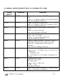
Options Available
a.
Interface Modules for training purpose (Calculator Keyboard, Elevator, Display, ADC with
DAC, Dual Slope ADC, Dual DAC, Logic Controller, Crystal Clock Divider, Traffic Lights,
RTC, Tone Generator, Stepper Motor, 8-bit, 16 Channel ADC etc.,)
b.
26 Core Ribbon Cable Connector Set.
SPECIFICATIONS
CPU
:
8085 Operated at 3.072 MHz
Memory
:
Three 28-pin JEDEC sockets offer 64K Bytes of memory as follows:
16 K Bytes of firmware in one 27128
4K/8K/16K expansion through 2732/2764/6264/27128
32KB of static RAM using one 62256 with battery backup.
Firmware :
Serial and Keyboard Monitors.
Centronics Printer Interface Driver Software.
EPROM Programming Software.
Audio Tape Interface Driver Software
Peripherals
8279:
To control 32 keys keyboard and 6-digit, 0.5" seven segment LED display.
8253:
3 Programmable interval timers
Timer 0 is used for implementing single-step facility, Timer 1 is used for
generating baud clock and Timer 2 is available to the user (Through jumper option,
user can use Timer 1 also, if user does not use it for baud clock).
8251:
For serial communication supporting all standard bauds from 110 to 19,200. (Baud
is selected through on-board DIP switch)
8255:
Two numbers are available to user giving 48 programmable I/O lines.
__________________________________________________________________________________________
MPS 85-3 User‟s Manual
1- 2
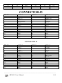
Interface Signals
CPU BUS
:
Demultiplexed and buffered TTL compatible signals brought-out to two
26 pin ribbon cable (spectra-strip type) connectors.
Parallel I/O :
48 lines (2 X 8255) of TTL compatible bus brought-out to two spectra-strip
type ribbon cable connectors.
Serial I/O
RS-232C with standard MODEM control signals through on-board 9 pin D-type
female connector.
:
Interrupts
All interrupts except TRAP (used for single-step implementation) are available to user.
Power Supply (Optional)
+5V, ( 0.1V), 3A
+12V,( 1.0V), 250mA
-12V, ( 1.0V), 100mA
30V, ( 2.0V), 100mA
__________________________________________________________________________________________
MPS 85-3 User‟s Manual
1- 3
CHAPTER
2
CONFIGURATION AND
INSTALLATION
2.1 CONFIGURATION OF MPS 85-3
MPS 85-3 Microprocessor trainer is versatile and can be configured in a number of ways as
determined by the settings of a DIP switch and other jumpers (refer to the component layout
diagram in Appendix C to locate the DIP switch and the jumpers). This chapter describes all the
configuration options and the installation procedures.
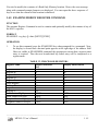
2.1.1 OPERATIONAL MODE SELECTION
MPS 85-3 can be operated either in the hexadecimal keypad mode or in the serial mode. In the
hexadecimal keypad mode the trainer is operated from the hexadecimal keyboard/display unit.
In the serial mode, the trainer is connected to a host PC through an RS-232C interface. In either
mode of operation, the system provides a variety of commands for program
development/debugging. The selection of the desired mode of operation is done as follows:
Switch 4 of the DIP switch
OFF
ON
Operational mode
Hexadecimal Keyboard mode.*
Serial mode
(* Default factory setting)
Chapter 3 describes the commands available in keyboard mode and chapter 4 describes the
commands available in serial mode.
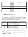
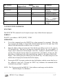
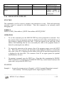
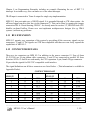
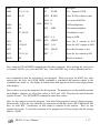
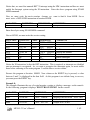
2.1.2 BAUD RATE SELECTION
In the serial mode of operation, MPS 85-3 configures the on-board 8251A USART as follows:
__________________________________________________________________________________________
MPS 85-3 User‟s Manual
1- 4
asynchronous mode
8 Bit character length
2 stop Bits
no parity
Baud Rate factor of 16X
Timer 1 of the on-board 8253A provides the transmit and receive baud clocks for the USART.
(Refer chapter 5 for a detailed discussion of the Hardware). This timer is initialised by the
system firmware to provide proper baud clock based on the settings of the DIP switch
as shown below:
Baud rate selection
S3
ON
ON
ON
ON
OFF
OFF
OFF
OFF
S2
ON
ON
OFF
OFF
ON
ON
OFF
OFF
S1
ON
OFF
ON
OFF
ON
OFF
ON
OFF
Baud rate
110
300
600
1200
2400
4800
9600*
19,200
(* Default factory setting)
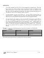
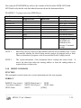
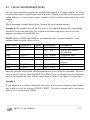
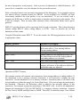
2.1.3 MEMORY SELECTION
MPS 85-3 has three 28-Pin sockets labelled U1,U2,U3 for memory. Two of these sockets are
populated and the third one is for expansion by the user. System firmware (16K bytes) is
supplied in a 27128 EPROM at the socket U1. 32K bytes of static RAM is provided by a
62256 at the socket U3.
The other socket, U2 is for user expansion. This socket can be configured, through jumper
settings JP1 and JP2 to accept 2732, 2764 or 27128 to provide 4K, 8K or 16K bytes of ROM.
Alternatively it can accept 6264 RAM to provide 8K RAM. As installed at the factory, the
jumpers are set for 27128 option. But the socket is left unpopulated. The configuration can be
set as shown below.
__________________________________________________________________________________________
MPS 85-3 User‟s Manual
1- 5
Device
Address Range
4K EPROM
(4000H-4FFFH)
(5000H-5FFFH)
(6000H-6FFFH)
(7000H-7FFFH)
8K EPROM
(4000H-5FFFH)
(6000H-7FFFH)
8K RAM
(4000H-5FFFH)
(6000H-7FFFH)
16K EPROM
(4000H-7FFFH)
2732
2764
6264
27128
Jumper Setting
JP2
BC
--
--
--
--
JP2
AB *
(* Default factory setting.)
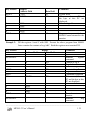
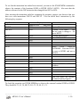
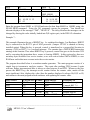
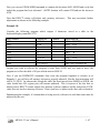
2.1.4 INTERRUPT AND RESET IN SELECTION
The sources for the vectored interrupts, RST5.5, RST6.5, RST7.5 and the TRAP can be selected
to be either on-board signals or off-board signals. However, please note that the source for
TRAP is configured to be the OUT0 signal from the timer. This selection is necessary for
implementing the single-step facility provided by both the keyboard monitor and serial monitor.
Further, the reset input to the CPU can be selected to come from either the on-board RESET key
or from an off-board source. Their default settings are shown below
Jumper setting
JP3 = AB
JP7 = BC
JP6 = AB
BC
JP5 = BC
AB
CD
Interpretation
: RST 7.5 source is external signal RST7.5
: RST 7.5 source is on-board signal KBINT(*)
: RST 6.5 source is external signal RST6.5[*]
: RST 6.5 source is on-board signal RXRDY
: RST 5.5 source is external signal RST5.5[*]
: RST 5.5 source is on-board signal 8279
INT
: RST 6.5 source is external signal RST6.5
Connector & pin no.
(J3-7)
(J3-3)
(J4-7)
(J4-7)
[*] Default factory setting.
Connector & pin no. indicates to which pin of which connector, external signal has to be
connected.
__________________________________________________________________________________________
MPS 85-3 User‟s Manual
1- 6
2.2 INSTALLATION OF MPS 85-3
To install MPS 85-3, the following accessories are required.
a)
Power Adapter
+ 5V, 3.0 Amp
b)
For Serial mode of operation :
Host PC with RS-232C interface
with the driver software for host PC (Refer chapter 7 for details).
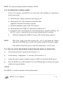
2.2.1. INSTALLATION PROCEDURE FOR SERIAL MODE OF OPERATION :
a)
Select serial mode of operation (Ref. Section 2.1.1)
b)
Select desired baud rate (Ref. Section 2.1.2)
c)
Select interrupt sources if required (Ref. Section 2.1.4)
d)
Select memory configuration if needed (Ref.Section 2.1.3)
e)
Connect MPS 85-3 to the Host PC through RS-232C cable (Appendix E describes the
RS-232C interface requirements) over the connector J6. (Refer appendix C for locating
the connectors)
If a host PC is being used, turn on the host PC and execute the driver program. (Ref.
Chapter 7 for details).
f)
Connect the power supply of required capacity to MPS85-3 and turn ON the power.
g)
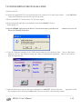
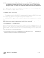
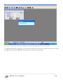
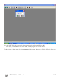
Press the RESET Key on MPS 85-3. Now the following sign-on message should appear
on the console.
MPS85-3 Serial Monitor V 1.1
(V 1.1 indicates version 1 and revision 1)
The sign-on message is followed by the command prompt, "." in the next line. Now
MPS85-3 is ready for operation in serial mode.
__________________________________________________________________________________________
MPS 85-3 User‟s Manual
1- 7
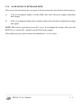
NOTE : The keyboard display module will display "SErIAL"
2.2.2. NO RESPONSE IN SERIAL MODE
If there is no response from MPS 85-3 in serial mode, after installing it as described in
the previous section,
a) Check the power supply connections and voltage levels.
b) Check the RS-232C cable connections at both the ends.
(Appendix E describes the interface in detail)
c) Check the handshake signals of RS-232C interface.
d) Check the baud rates of MPS 85-3 and the host connected to it.
e) If a host PC is the controlling device, check that the driver program is running, the
RS-232C cable is connected to the correct port and that the port is working.
f)
NOTE :
Check the configuration of MPS 85-3 again. (DIP Switch settings, jumpers).
DIP switch status is read only at power ON / reset. If you change the settings,
either press the RESET key or switch OFF and then switch ON the power supply.
If the problem still persists, please contact the manufacturer / service center.
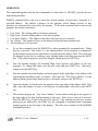
2.2.3. INSTALLATION PROCEDURE FOR KEYBOARD MODE OF OPERATION
a)
Select Keyboard mode of operation (Ref. Section 2.1.1).
b)
Set the memory configuration if necessary (Ref. Section 2.1.3).
c)
Connect the power supply of required capacity to MPS 85-3 and switch ON the power.
d)
Press the RESET key of the Keyboard. Now the following sign-on message will appear
on the seven-segment display.
-UPS 85
Now MPS85-3 is ready for operation in the keyboard mode.
__________________________________________________________________________________________
MPS 85-3 User‟s Manual
1- 8
2.2.4.
NO RESPONSE IN KEYBOARD MODE
If the correct sign-on message does not appear in the keyboard mode, then check the following items.
a)
If the seven-segment display is totally blank, then check the power supply connections
and voltages.
b)
If the seven-segment display shows random pattern, then check the configuration settings
once again.
NOTE: DIP switch is read only at power ON / reset. If you change the settings, either press the
RESET key or switch OFF and then switch ON the power supply.
If the problem persists, please contact the manufacturer / service center.
__________________________________________________________________________________________
MPS 85-3 User‟s Manual
1- 9
CHAPTER
3
KEYBOARD MONITOR
3.1 INTRODUCTION
This chapter describes the commands supported by the keyboard monitor program. In the
keyboard mode, the user enters the commands and data by pressing the appropriate keys on the
keypad. Responses are displayed by the system on the six-digit LED display.
Whenever the monitor expects a command, the display shows a dash(“-“) at the left edge of the
address field, possibly along with an error message or with the sign-on message upon reset.
Thus, it should be noted that irrespective of the characters appearing in the rest of the display, a
dash at the left edge of the display always is a command prompt. When the monitor expects a
parameter, a decimal point will be displayed at the right edge of the field into which the
parameter is to be placed. The parameter will be either an address to be entered in the address
field or a byte of data to be entered in the data field (The only exception, explained later, occurs
in the use of the EXAM REG command). The valid range for an address parameter is from 1 to
4 hexadecimal digits and the valid range for a data parameter is from 1 to 2 hexadecimal digits.
Longer numbers may be entered but such numbers are evaluated modulo 64k or 256
respectively, i.e. only the last four or the last two digits entered will be accepted.
The RESET key causes a hardware reset and restarts the monitor. The monitor displays the sign
ON message (-UPS 85) across the address and data fields of the display. Now the monitor will
be ready to accept the commands from the user. But the monitor does not save the information
about the state (register values etc.,) of any previous user program. However, the monitor does
not disturb contents of the user portion of the RAM area.
3.2 RAM USAGE
The system monitor utilizes RAM locations 8F90H to 8FFFH for Storing the System Stack and
variables. User programs should not disturb this area; otherwise the results are unpredictable.
__________________________________________________________________________________________
MPS 85-3 User‟s Manual
1 -10
3.3 KEYBOARD AND DISPLAY
As noted already, the display consists of 6 seven-segment LED displays, separated into two
fields. The left field, called the address field consists of 4 digits and the right field called the
data field consists of 2 digits.
The 32 key keyboard consists of the following groups of keys.
a.
Hexpad: 16 keys representing the hexadicimal digits 0 through F. In the use of the
EXAM REG command, some of these keys represent register names also, as indicated by
the legends on the keytops. This usage is further explained in the description of the
EXAM REG command. Further, six of these keys serve the functions of command keys
also. The context of operation defines the meaning of the key.
b.
Command group: 11 command keys two of which are USER DEFINED.
commands are in addition to the six commands mentioned above.
c.
Delimiter group: 3 keys (NEXT, PREV, EXEC) which serve as the delimiters while
entering the commands/data.
d.
System operation keys: RESET and KBINT keys. RESET key, as already noted causes
a hardware reset of the system. KBINT key is connected to the RST 7.5 input. It‟s use is
explained in chapter 8.
These
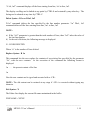
3.4 MONITOR COMMANDS
The keyboard monitor is capable of executing ten individual commands, summarized in Table
3.1. Each command is represented by exactly one key with appropriate legend on the keytop.
The commands are described in detail in the following sections. In both the table and individual
command descriptions, the following notation is used :
Upper case letters and numbers represent keyboard keys :
[A] indicates that „A‟ is an optional entry ;
A/B indicates that either „A‟ or „B‟ must be entered ;
[A]*
indicates zero or more optional occurences of „A‟ ;
<B>indicates a 1 or 2 bytes parameter to be entered by the user.
__________________________________________________________________________________________
MPS 85-3 User‟s Manual
1 -11
TABLE 3.1 KEYBOARD MONITOR COMMAND SUMMARY
COMMAND
EXAMINE/MODIFY
MEMORY
EXAMINE/MODIFY
REGISTER
SINGLE STEP
GO
BLOCK MOVE
INSERT
DELETE
INPUT BYTE
OUTPUT BYTE
FUNCTION/FORMAT
Displays/Modifies the contents of a memory
location.
EXAM MEM <add>
NEXT
[<data>] NEXT/PREV] EXEC
Displays/modifies 8085 register contents. EXAM
REG <reg key>
[[<data>] NEXT]* EXEC
Executes a single user program instruction.
SINGLE STEP <Start addr>
NEXT
[[<Start addr>] NEXT]*
EXEC.
Transfers control from monitor to user program
Go<addr> EXEC
Moves a block of data from one portion to another.
BLK MOVE <start Addr>
NEXT
<end addr> NEXT <DEST ADDR>
EXEC
Inserts one or more instructions in the user program.
INSERT[<Low limit>]
[<High Limit>]NEXT<Low Insert Addr>
NEXT, <No. of bytes>
NEXT
<DATA>*
EXEC
Deletes one or more instructions in the user program.
DELETE [<Low Limit>]
NEXT
[<High Limit>] NEXT<Low delete addr>
NEXT <High Delete addr>
EXEC
Inputs a byte from the specified port
INBYTE <port address>
NEXT
[NEXT] *
EXEC
Outputs a byte to the specified port
OUT BYTE <port address>
NEXT
<data> [NEXT <data>]*
EXEC
__________________________________________________________________________________________
MPS 85-3 User‟s Manual
1 -12
3.4.1
EXAMINE/MODIFY MEMORY COMMAND
FUNCTION
This command is used to examine the contents of selected memory locations. The contents can
be optionally modified if the memory location is in RAM area.
FORMAT
EXAM MEM <address> NEXT [[<data> NEXT/PREV]* EXEC
OPERATION
1.
To use this command, press the EXAM MEM key when prompted for a command.
When this key is pressed, the display is cleared and a dot appears at the right edge of the
address field indicating that an address entry is required.
2.
Enter the memory address of the byte to be examined. This value is displayed in the
address field of the display.
3.
After entering the address value, press the NEXT key. The data byte at the addressed
memory location will be displayed in the data field and a decimal point (a dot) appears at
the right edge of the data field indicating that data can be updated.
4.
If the contents of the addressed memory location are only to be examined, press the
EXEC key to terminate the command, or press the NEXT key to examine/modify the
next consecutive memory location or the PREV key to examine/modify the previous
memory location.
5.
To modify the contents of an addressed memory location, enter the new data from the key
board (note that data values are evaluated modulo 256). However, this new value,
displayed in the data field is not entered into the addressed memory location till NEXT or
EXEC or PREV is pressed.
ERROR CONDITIONS : Error conditions occur while attempting to modify a non-existent or
Read-Only Memory (ROM) location. Note that the error is not detected until the PREV or
NEXT or EXEC key is pressed. When an error is detected, the characters „Err‟ are displayed
along with the command prompt character (-) in the address field.
Example 1 : Examining a series of memory locations starting from 0000H (the start of keyboard
monitor).
__________________________________________________________________________________________
MPS 85-3 User‟s Manual
1 -13
Key Pressed
RESET
EXAM MEM
0
Display
Address Field
-UPS
Comments
Data Field
85
System Reset
Examine Memory command
First memory location
To be examined 0000H
Contents of this location.
Next location and its contents.
Next location and its contents
Previous location and its contents.
Command termination/prompt.
System Reset
Examine Memory command.
0000.
NEXT
NEXT
NEXT
PREV
EXEC
RESET
EXAM MEM
8
D
0000
0001
0002
0001
-UPS
.
0008.
008D.
0
0
NEXT
A
F
EXEC
08D0.
8D00.
8D00
8D00
8D00
-
F3.
3E.
0F.
3E.
85
Memory location to be examined &
modified.
XX.
0A.
AF.
Contents of this location.
New data to be entered
Command termination prompt
To check that data was updated successfully, press EXAM MEM key and enter memory address
8D00H and note that “AF” is displayed in the data field when NEXT key is pressed.
Example 3: Trying to modify ROM location.
Key Pressed
RESET
EXAM MEM
A
NEXT
F
A
NEXT
Display
Address Field
-UPS
.
000A.
000A
000A
000A
-Err
Comments
Data Field
85
10.
0F.
FA.
System Reset
Examine Memory command.
Address of location to be examined.
Contents of this location
New data to be entered
Error message
__________________________________________________________________________________________
MPS 85-3 User‟s Manual
1 -14
You tried to modify the contents of a Read Only Memory location. Hence, the error message
along with command prompt character was displayed. You can repeat the above sequence of
keys to see that the content of this location is unaltered.
3.4.2. EXAMINE/MODIFY REGISTER COMMAND
FUNCTION
The examine Register Command is used to examine and optionally modify the contents of any of
the 8085‟s registers.
FORMAT
EXAM REG <reg key>[[<data>]NEXT]*[EXEC]
OPERATION
1.
To use this command, press the EXAM REG key when prompted for a command. Now,
the display is cleared and a decimal point appears at the right edge of the address field.
However, unlike in EXAM MEM command, this prompt now means that a register name
entry is required. Thus the next hexadecimal key board entry will be interpreted as a
register name.
TABLE 3.2. PROCESSOR REGISTERS
Register Name
Register identifier
Display abbreviation
Key
Register A
A
A
Register B
B
B
Register C
C
C
Register D
D
D
Register E
E
E
Flags Register
F
F
Interrupt Mask
3/I
I
Register H
8/H
H
Register L
9/L
L
Stack Pointer High byte
4/SPH
SPH
Stack Pointer Low byte
5/SPL
SPL
Program Counter High byte
6/PCH
PCH
Program Counter Low byte
7/PCL
PCL
__________________________________________________________________________________________
MPS 85-3 User‟s Manual
1 -15
FORMAT OF INTERRUPT MASK I:
0
0
0
0
IE M7.5
M6.5
M5.5
Interrupt Masks
Interrupt Enable Flag
FORMAT OF THE FLAG BYTE F:
S
Sign
Z
Zero
X
AC
Auxilary
Carry
X
P
Parity
X
C
Carry
Fig 3.1 : FORMAT OF I and F REGISTERS
2.
When the hexadecimal key is pressed, the corresponding register abbreviation is
displayed in the address field and the contents of this register are displayed in the data
field and a data update prompt (dot) appears at the right edge of the data field. Table 3.2.
defines the 8085 register names, the hexadecimal keyboard acronyms, the abbreviations
appearing in the address field of the display and the sequence in which the registers are
displayed. The formats of the flag byte F and interrupt mask I are shown in Figure 3.1
3.
When the register contents are displayed (with the data update prompt), the contents of
this register can be modified if desired. To do this, enter the new value from the
keyboard. This new value will be displayed in the data field and the register contents are
updated when either the NEXT or EXEC key is pressed.
4.
After examining and optionally modifying the contents, if the EXEC key is pressed, the
command is terminated. If the NEXT key is pressed, the abbreviation and contents of the
“next register” (according to the order shown in Table 3.2) are displayed and opened for
modification. Note that the sequence is not cyclic and thus pressing the NEXT key when
the PCL is displayed will terminate the command.
__________________________________________________________________________________________
MPS 85-3 User‟s Manual
1 -16
Key Pressed
RESET
EXAM REG
Address Field
-UPS
.
8/H
8
NEXT
H
H
L
EXEC
-
Display
Data Field
85
XX.
08.
XX.
Comments
System Reset
Examine
Register
Command
Contents of register
New data
H register updated
Next
register‟s
contents displayed
Command termination
prompt.
3.4.3 INPUT BYTE COMMAND
FUNCTION
The INPUT BYTE command is used to input (accept) a byte of data from an input port.
FORMAT
IN BYTE <port address> NEXT [NEXT] * EXEC
OPERATION
1.
To use this command, press the INBYTE key when prompted for command. When this
key is pressed, the display is cleared and a decimal point appears at the right edge of the
address field indicating that an address entry is required
2.
Enter the address of the port to be read. Note that the port address can be in the range 0255 (decimal) only. Thus only 2 hex digits are required to specify the port address. If
longer value is entered, the last four digits entered are displayed until the NEXT key is
pressed. Then only the last two digits are accepted as the port address. In any case, this
port address is duplicated in the most significant two digits of the address field of the
display. After entering the port address, press the NEXT key. The addressed port is read
and the data is displayed in the data field of the display.
3.
Pressing the NEXT key again, updates the data field display with the current data byte at
the addressed input port. Pressing the EXEC key terminates the command and the
command entry prompt(„-„) appears.
NOTE : The I/O ports provided on MPS 85-3, their addresses and usage are described in
detail in chapter-5 on Hardware.
__________________________________________________________________________________________
MPS 85-3 User‟s Manual
1 -17
Example :
Input the byte from the port 50H (i.e. baud switch status)
Key Pressed
RESET
IN BYTE
Display
Address Field
Data Field
-UPS
85
.
Comments
System Reset
Input Byte command
5
0005.
Port Address
0
NEXT
NEXT
NEXT
EXEC
0050
5050
5050
5050
-
Input data byte
XX
XX
XX
Current data byte
Current data byte
Command termination prompt
3.4.4. OUTPUT BYTE COMMAND
FUNCTION
The OUTPUT BYTE command is used to output a byte of data to an output port.
FORMAT
OUTPUT <port address>NEXT<data>[NEXT <data>] * EXEC
OPERATION
1.
To use this command, press the OUTBYTE key when prompted for command. When this
key is pressed the display is cleared and a decimal point appears at the right edge of the
address field indicating that an address entry is required.
2.
Enter the desired port address. Note that the port address can be in the range 0-255
(decimal) only. Thus only 2 hex digits are required to specify the port address. If longer
value is entered, the last four digits entered are displayed until the NEXT key is pressed.
Then only the last two digits are accepted as the port address. In any case, this port address
is duplicated in the most significant two digits of the address field of the display. After
entering the desired port address, press the NEXT key.
__________________________________________________________________________________________
MPS 85-3 User‟s Manual
1 -18
3.
Now a decimal point appears at the right edge of the data field indicating that the data byte
to be output can now be entered using the hexadecimal keyboard; enter the data byte to be
output.
4.
After entering the data, press the EXEC key to output the byte to the port and to terminate
the command, or press the NEXT key if additional data is to be output to the addressed port.
NOTE : As mentioned in the previous section, the I/O ports provided on MPS85-3, their
addresses and usage are explained in detail in chapter 5.
Example :
Output a string of ASCII characters (ESA) to the data port of the USART (8251)
to be transmitted to a CRT terminal through the on-board RS-232-C interface
Key Pressed
RESET
OUT BYTE
(20)
NEXT
4
5
NEXT
5
3
NEXT
4
1
EXEC
Display
Address Field
-UPS
.
0020.
2020
2020
2020
2020
2020
2020
2020
2020
2020
-
Comments
Data Field
85
04.
45.
.
05.
53.
.
04
41
System Reset
Output Byte command 2
Port address
Send „E‟
Send „S‟
Send „A‟
Command termination prompt
3.4.5 GO COMMAND
FUNCTION
The GO command is used to transfer control of the system from the monitor to user‟s program
FORMAT
GO address EXEC
__________________________________________________________________________________________
MPS 85-3 User‟s Manual
1 -19
OPERATION
1.
To use this command, press the GO key when prompted for command entry. When this
key is pressed, the current contents of the User Program Counter are displayed in the
address field and the contents of the location addressed by the PC are displayed in the
data field. A dot also appears at the right edge of the address field indicating that the user
can update the value of User Program Counter if required.
2.
To begin Program execution, press EXEC key. Now the address and data fields are
cleared, and “E” is displayed at the left edge of the address field and control is then
transferred to the user program at the current value of the user program counter.
3.
To return control to the monitor, you can write the RST 5 instruction (opcode=EFH) at
the end of your program. When this instruction is executed, monitor regains control of
the system and full information about the user program is saved. Another way to exit
from a running program and return control to the monitor is to press the RESET key.
However, in this case, all register information about user program is lost. Note that in
any case the contents of the user portion of the RAM area are not disturbed by the
Monitor.
Example 1 : Suppose the following program is entered in the memory by EXAM MEM
command.
Location
Object Code
Mnemonic
8800
3E
MVI A,42
8801
42
8802
4F
MOV C,A
8803
EF
RST 5
To run this program, press the keys according to the following sequence.
__________________________________________________________________________________________
MPS 85-3 User‟s Manual
1 -20
Key Pressed
RESET
GO
Display
Address Field
-UPS
XXXX.
Data Field
85
XX
8
8
0
0
EXEC
0008.
0088.
0880.
8800.
-UPS
85
Example 2:
Comments
System Reset
GO command; current PC and
the byte at this PC are
displayed.
New starting address
Program is executed from
8800H Control returned to the
monitor
Fill the registers A and C with 00H. Execute the above program from 8800H.
Later examine the contents of reg A&C. Both the registers must contain 42H.
Key Pressed
RESET
EXAM REG
Address Field
-UPS
.
A
0
NEXT
NEXT
0
EXEC
GO
A
A
B
C
C
XXXX.
8
8
0
0
EXEC
0008.
0088.
0880.
8800
-UPS
EXAM REG
.
Display
Data Field
85
XX.
00.
XX.
XX.
00.
XX
85
Comments
System Reset
Examine
register
command.
Content of reg A
Reg A altered.
Content of reg B
Content of reg C
Reg C altered
Command terminated
GOcommand; Current
PC and the byte at this
PC are displayed.
New value of the PC
Control returns to
monitor.
Examine
Reg
command
__________________________________________________________________________________________
MPS 85-3 User‟s Manual
1 -21
A
NEXT
NEXT
EXEC
3.4.6
A
B
C
-
42.
XX.
42.
Contents of reg A
Contents of reg B
Contents of reg C
Control returns to
monitor due to the
break-point.
SINGLE STEP COMMAND
FUNCTION
This command is used to execute a program, one instruction at a time. With each instruction
executed, control is returned to the monitor. Thus this command is an extremely useful
debugging tool.
FORMAT
SINGLE STEP [<Start address>] NEXT<Start address>NEXT]]*EXEC
OPERATION
1.
To use this command, press the SINGLE STEP key when prompted for command. Now
the contents of the user program counter are displayed in the address field and the byte at
this location is displayed in the data field. A dot also appears at the right edge of the
address field indicating that the user can modify the value of the program counter if
desired, by entering the new address.
2.
To execute the instruction at the current value of the program counter, press the NEXT
key. When this key is pressed, the instruction at the displayed address is executed the
new value of user PC is displayed in the address field and its associated instruction byte
is displayed in the data field. The contents of the PC are again opened for optional
modification by the user.
3.
To terminate command, press the EXEC key. (Note that after terminating the SINGLE
STEP Command, if you again press the SINGLE STEP key, control returns exactly to the
point where you pressed the EXEC key).
EXAMPLES
Example 1. Assume the program given in Example 1 of GO Command illustration is entered
in the memory. Now this program can be single-stepped as follows.
__________________________________________________________________________________________
MPS 85-3 User‟s Manual
1 -22
Key Pressed
RESET
SINGLE STEP
Address Field
-UPS
XXXX.
8
8
0
0
NEXT
0008.
0088.
0880.
8800.
8802
NEXT
EXEC
8803
-
3.4.7
Display
Data Field
85
XX
Comments
System Reset
Current value of PC
and the byte at this PC
New value of PC
4F
EF
Instruction at 8800 is
executed.
Next
instruction
to
be
executed is displayed.
Next instruction
Command termination
BLOCK MOVE COMMAND
This command is used to move a block of data from one area of the memory to another area.
FORMAT
BLK MOVE<Start address>NEXT<end address> NEXT<destination address>EXEC
OPERATION
1.
To use this command, press the BLK MOVE key when prompted for command entry.
When this key is pressed, display field is cleared and decimal point appears at the right
edge of the address field.
2.
Now enter the starting address of the block of data to be moved. Press the NEXT key.
Now the display field is again cleared and again a decimal point appears at the right edge
of the address field. Now enter the ending address of the block of data to be moved.
Press the NEXT key. Monitor clears the display field and a decimal point appears at the
right edge of the address field. Now enter the starting address of the area into which the
block of data is to be moved. This address is called the destination address. Press the
EXEC key to start the command execution.
__________________________________________________________________________________________
MPS 85-3 User‟s Manual
1 -23
3.
Monitor now moves the block of data from start address to end address, to the area
beginning at the destination address. After moving the data, monitor displays the
command prompt sign.
ERROR CONDITIONS
1.
Specifiying a value for the end address of the source block which is less than the value of
the start address of the source block.
2.
Trying to move the data into non-existent or Read Only Memory.
EXAMPLES:
Example 1: Moving the block of program code listed in the example for the GO command.
Key Pressed
RESET
BLK MOVE
8
Address Field
-UPS
.
0008.
8
0
0
NEXT
8
0088.
0880.
8800.
.
0008.
8
0
3
NEXT
8
8
2
0
EXEC
0088.
0880.
8803.
.
0008.
0088.
0882.
8820.
-
Display
Data Field
85
Comments
System Reset
Block move command
Start address of
source block
End address of source
block.
Destination address.
Block move operation
successful. Command
prompt
__________________________________________________________________________________________
MPS 85-3 User‟s Manual
1 -24
Now using the EXAM MEM key observe the contents of the locations 8820H, 8821H and
8823H and verify that the code has indeed been moved into the destination block.
EXAMPLE 2: Trying to move into EPROM area
Key Pressed
Address Field
-UPS
.
0000.
.
000F.
.
0002.
0020.
-Err
RESET
BLK MOVE
0
NEXT
F
NEXT
2
0
EXEC
Display
Data Field
85
Comments
System Reset
Block move command
Start address
End address
Destination address
Attempt to move data
into ROM area
resulted in error
message. Command
prompt
NOTE 1 :
Block move moves a block of data contents from one area to another area. It does
not consider whether the block being moved consists of program code or data.
Thus no relocation of program code occurs and the block is simply moved.
NOTE 2 :
The system determines if the destination block overlaps the source block. It
moves the data from either the starting address or from the ending address as
required when overlap exists.
3.4.8
INSERT COMMAND
FUNCTION
This command is used to insert one or more instructions into the user program.
FORMAT
INSERT[<Low-Limit>]
<Low Insert Address>
NEXT<Data>
NEXT[<High-Limit>]
NEXT
NEXT.<No of bytes>
NEXT<data>
NEXT…
[EXEC]
__________________________________________________________________________________________
MPS 85-3 User‟s Manual
1 -25
OPERATION
This command together with the next command to be described viz. DELETE, provide the user
mini-editing facilities.
INSERT command allows the user to insert the desired number of bytes into a program at a
specified address. The address references in the program, which change because of this
insertion, are automatically corrected by the monitor. To do such corrections and to relocate the
program, the monitor must know:
1.
2.
3.
4.
5.
Low Limit : The starting address of the user program
High Limit : Present ending address of the user program.
Low-Insert Address : The address from where the bytes are to be inserted.
No. of bytes : The number of bytes to be inserted (in hexadecimal notation) and
The actual bytes to be inserted.
a)
To use this command, press the INSERT key when prompted for command entry. When
this key is pressed, “Low Limit” (i.e. the starting address of the program as remembered
by the monitor from previous operations) is displayed in the address field. This value can
be changed by the user by entering a new starting address and then pressing the NEXT
key. If the value displayed is not to be changed, simply press the NEXT key.
b)
Now the monitor displays the assumed High Limit (present end address of the user
program). To change this value, enter the new value and press NEXT key. Otherwise,
simply press the NEXT key.
c)
Now the monitor clears the display and a dot appears at the right edge of the address field
indicating that an address entry is required. Now enter the “Low Insert Address” (i.e the
address starting from which insertions are to be made) and press the NEXT key.
d)
Again the display is cleared and a dot appears at the right edge of the address field. This
time, enter the number of bytes to be inserted, in hexadecimal, followed by the NEXT
key.
e)
The monitor displays the “Low Insert Address” in the address field and a dot appears at
the right edge of the data field prompting a data entry. Enter a byte value to be inserted.
Press the NEXT key if more bytes are to be entered. After entering the last byte, or after
entering a byte followed by the EXEC key, the command is terminated and a command
prompt appears at the left edge of the display. Thus this step is similar to EXAM MEM
command operation.
__________________________________________________________________________________________
MPS 85-3 User‟s Manual
1 -26
The monitor inserts the new bytes into the user program and makes appropriate changes to the
address references that are to be changed because of the insertion.
NOTES :
1.
The monitor treats the entire program segment from LOW LIMIT to HIGH LIMIT as
relocatable and adjusts all memory reference. Hence, if the inserted program fragment
refers to locations within itself, then care must be taken to see that “No. of bytes” is
subtracted from all such references before entering them.
2.
As the size of the program grows, when a number of bytes are inserted, the user should
ensure that there is sufficient free memory available beyond the current end address of
the user program.
3.
Relocation is explained in detail in chapter 8 on Programming Examples.
ERROR CONDITIONS
1.
Specifying a “Low Insert Address” value that is greater than the value of the
“High Limit”.
2.
Trying to insert instruction in non-existent or Read-Only Memory.
Example :
Example on the usage of INSERT command is provided in the next section, after
describing the DELETE Command.
3.4.9. DELETE COMMAND
FUNCTION
This command is used to delete one or more instructions from the user program.
FORMAT
DELETE[<LOW LIMIT>]
LOW DELETE ADDRESS>
NEXT[<HIGH LIMIT>]NEXT
NEXT<HIGH DELETE ADDRESS> EXEC
__________________________________________________________________________________________
MPS 85-3 User‟s Manual
1 -27
OPERATION
This command allows the user to delete one or more instructions from a program. The address
references to be changed because of this deletion process, are changed automatically by the
monitor. The interpretation of the parameters appearing in the format of the command is same as
in the INSERT command, described in the previous section.
1.
To use this command, press the DELETE key when prompted for command entry. Now
the LOW-LIMIT is displayed in the address field. The LOW-LIMIT can be optionally
changed by the user. Then the user must press the NEXT key. Now the monitor displays
the HIGH-LIMIT. After modifying this if desired, press the NEXT key.
2.
Now the display is cleared and a dot appears at the right edge of address field indicating
that an address entry is required. Enter “LOW DELETE ADDRESS” (i.e. the address
starting from which instructions are to be removed) and press the NEXT key.
3.
Again the display is cleared and a dot is displayed at the right edge of the address field.
Enter the „HIGH DELETE ADDRESS” (i.e. the address of the last byte to be removed
from the user program) and press the EXEC key.
4.
Monitor deletes all the bytes from “LOW DELETE ADDRESS” to “HIGH DELETE
ADDRESS”. It then makes appropriate changes to all address references in the program
form “LOW LIMIT” to “HIGH LIMIT”.
ERROR CONDITION
Specifying a “LOW DELETE ADDRESS” which is greater than “HIGH
LIMIT” or “HIGH DELETE ADDRESS”.
EXAMPLE :
This example illustrates the use of INSERT and DELETE commands.
Assume that the following program has already been entered in to memory using the EXAM
MEM Command.
LOCATION
8830
8831
8832
8833
8834
8835
8836
8837
8838
8839
883 A
VALUE
C5
0B
78
B1
C2
31
88
C1
D1
E1
C9
DELAY :
INSTRUCTION
PUSH B
DCX B
MOV A,B
ORA C
JNZ DELAY
POP B
POP D
POP H
RET
__________________________________________________________________________________________
MPS 85-3 User‟s Manual
1 -28
Now, suppose, you discovered that you did not intialise BC register pair before starting the
DELAY. You can insert one instruction, say LX1 B, 3030H starting at the location 8831 by the
following key sequence.
Key Pressed
Display
RESET
INSERT
8
Address Field
-UPS
XXXX.
0008.
8
3
0
NEXT
8
8
3
A
NEXT
8
8
3
1
NEXT
3
0088.
0883.
8830.
XXXX.
0008.
0088.
0883.
883 A.
.
0008.
0088.
0883.
8831.
.
0003.
NEXT
1
NEXT
3
0
NEXT
3
0
EXEC
8831
8831
8832
8832
8832
8833
8833
8833
-
Comments
Data Field
85
System Reset
Current Low-Limit
The Low Limit
program
of
user
Current High-Limit
The High-limit of the program
Low insert address
XX.
01.
XX.
03.
30.
XX.
03.
30.
Insert one instruction of 3
bytes
Start entering the instruction
Instruction inserted return to
command Prompt
__________________________________________________________________________________________
MPS 85-3 User‟s Manual
1 -29
To see that the instruction has indeed been inserted, you can use the EXAM MEM command to
observe the contents of the locations 8830H to 883DH (883A+3=883D). Also note that the
address reference for the JNZ instruction has changed from 8831 to 8834.
After inserting the instruction and after examining the program, suppose you discover that you
have two extra instructions POP D and POP H. You can delete these instructions by the
following key sequence
Key Pressed
RESET
DELETE
Display
Address Field
Data Field
-UPS
85
8830.
NEXT
8
8
3
D
NEXT
883A.
0008.
0088.
0883.
883D.
.
8
8
3
B
NEXT
0008.
0088.
0883.
883B.
.
8
8
3
C
EXEC
0008.
0088.
0883.
883C.
-
Comments
System Reset
Current LOW-LIMIT. You
do not want to change it. So
press NEXT
Current HIGH-LIMIT
New HIGH LIMIT
Enter
LOW
DELETE
ADDRESS. Note that POP D
is now at 883BH and not at
8838 H
Enter
HIGH
Address
DELETE
The two bytes are deleted.
Command prompt appears.
To check the operation, use EXAM MEM key to observe the contents location 8830H to 883BH.
They should be C5, 01, 30, 0B, 78, B1, C2, 34, 88, C1, C9.
__________________________________________________________________________________________
MPS 85-3 User‟s Manual
1 -30
3.5
USER DEFINED FUNCTION:
MPS85-3 trainer has two command keys whose functions can be defined by the user. These
keys labeled F1 & F2 are available in addition to the standard command keys described already.
When the user-defined function key F1 is pressed, monitor transfers control to a prespecified
location in RAM, 8F90H.
When the user-defined function key F2 is pressed, monitor transfers control to a prespecified
location in RAM, 8F94H.
Following Power ON/Reset, the monitor initializes this area with the instruction JMP Err.
Thus after Power ON/Reset, if you press the function keys, Error message along with the
command prompt (-Err) is displayed.
MAKING USE OF THE FUNCTION KEYS :
To use the user-defined function keys, the user must write appropriate instructions in the
locations reserved for the user function keys. Here is an example to show the use of function
keys. Note that as only 3 bytes (starting from 8F90H) are reserved for F1 key, the user
instruction will generally be a JMP instruction.
EXAMPLE
Assume that the user has written the software for programming a specific type of EPROM.
Assume that this program is assembled from location 4000H (expansion ROM area). One way
to invoke this routine would be to use the GO command to transfer control to this program. The
second way is to use the function key. Assume that the user has decided to use the key F1.
Thus, when F1 is pressed, the program at 4000H should gain control. To do this, user can set up
a JMP instruction at 8F90H as follows:
Location
8F90H
8F91H
8F92H
Byte value
C3
00
40
Now, whenever the F1 key is pressed, the EPROM programming routine at 4000H gets control
of the system.
__________________________________________________________________________________________
MPS 85-3 User‟s Manual
1 -31
NOTES :
1.
If the user inadvertently uses the locations reserved for the user function key, the results
of pressing the user defined function key are unpredictable.
2.
Note that the monitor initializes the location reserved for the key F1 & F2 keys with the
JMP Err instruction, following either power ON or RESET. Thus if the user writes
instructions in these reserved locations, subsequently presses the RESET key, then
instructions will be overwritten.
__________________________________________________________________________________________
MPS 85-3 User‟s Manual
1 -32
CHAPTER
4
SERIAL MONITOR
4.1 INTRODUCTION
This chapter describes the commands supported by the Serial Monitor Program. The Serial
Monitor allows MPS 85-3 to be operated from a host PC connected through RS-232C serial
interface (Refer to chapter 5 on Hardware and Appendix E on RS-232C connector Details)
The trainer must be configured for serial mode of operation as described in section 2.2.1.
When the system enters serial mode of operation, the sign-on message "MPS 85-3 SERIAL
MONITOR V 1.1" is displayed (the current version number and the revision number) on one
line and a period "." on the next line indicating that the monitor is ready to accept commands
from the user. With the exception of RESET and KBINT keys, the keyboard is
completely disabled.
4.2 RAM USAGE
The system monitor utilizes RAM locations from 8F90H to 8FFFH as scratch pad area for
system stack and variables. User programs should not alter this area, otherwise the results are
unpredictable.
4.3 STRUCTURE OF MONITOR COMMANDS
Whenever the monitor is ready to accept a command from the user, it outputs a period (`.') as the
command prompt character at the beginning of a new line.
The commands entered by the user consists of a single character command mnemonic followed
by a list of command parameters. This list may consist of upto four parameters depending on the
particular command being used. When more than one parameter is required, a single (`,') is used
between the parameters as a seperator.
__________________________________________________________________________________________
MPS 85-3 User‟s Manual
1 -33
A command is terminated either by a Carriage Return or by a comma, depending on the
command itself. Commands are executed one at a time and only one command is allowed within
one command line.
PARAMETER ENTRY
All numeric parameters are to be entered as hexadecimal numbers. The valid range for one byte
parameters is 00 to FF and if more than 2 digits are entered, only the last two digits are valid
(leading zeros may be omitted). Thus all one byte values are interpreted modulo 256 (decimal).
The valid range for 2-byte parameters is 0000 to FFFF and longer values are evaluated modulo
64K (i.e. only the last four digits are valid).
All the commands except the X (examine/modify register) command require only hexadecimal
values as parameters. The register name abbreviation entries required by the X command are
described later while describing the X command in detail.
RESPONSE TO ERRORS
Whenever an error is detected by the monitor (either in the command entry or in the command
execution) the command is aborted, the symbol (`?') is output on the command line, a carriage
return and a linefeed are issued and the command prompt character (`.') is output at the beginning
of a new line. (The possible error conditions are described while illustrating the individual
commands.)
Command execution occurs only after a valid delimiter (a comma or a carriage return depending
on the command) is entered. Hence a command entry can be cancelled anytime before the
delimiter is entered by "committing an error". That is, enter any character that is not legal for the
expected entry. The monitor detects this error, aborts the command, displays `?' symbol and
returns to command entry mode.
4.4. MONITOR COMMANDS
Each command described in this chapter consists of a single character, followed by apropriate
parameters and data. These commands are summarized in Table 4.1. and are described in detail
in the following sections. In the table as well as in the subsequent descriptions, the following
notation is used:
A capital letter indicates a command mnemonic:
[a] indicates an optional parameter `a'
a/b indicates either `a' or `b' to be entered
__________________________________________________________________________________________
MPS 85-3 User‟s Manual
1 -34
[b]* indicates the nature of a 1 or 2 byte hex value to be enterered by the user as a parameter
or data;
<CR> indicates a Carriage Return is to be entered.
Further, when describing the individual commands with example, output from the system is
underlined.
These symbols are used only to clarify the command formats and they are to be neither entered
by the user nor output by the system.
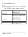
TABLE 4.1 SUMMARY OF SERIAL MONITOR COMMANDS
COMMAND
C (Compare Memory)
D (Display Memory)
G (GO)
M (Move Memory)
S (Substitute Memory)
X (Examine/Modify Registers)
FUNCTION/FORMAT
Compare a block of memory with destination block.
C <Start address>, <end address>,
<destination address> <CR>
Displays memory contents in line formatted output
D <Start address>,<end address> <CR>
Transfers the processor control from the
Monitor to user program with optional breakpoints.
G [<Start address>] ,
[<breakpoint address 1>, ]
[<breakpoint address 2>, ]
[<breakpoint address 3 >, ] <CR>
Moves a block of memory contents
M <Start address> , <end address>
<destination address> <CR>
Displays/Modifies memory locations
S <address> , /- [[<new data>]]* <CR>
Displays/Modifies the processor registers
X [<reg>] [[<new data>],] * <CR>
__________________________________________________________________________________________
MPS 85-3 User‟s Manual
1 -35
4.4.1
S (SUBSTITUTE MEMORY) COMMAND
FUNCTION
The S (Substitute Memory) command is used to examine the contents of specified memory
locations. Further, if the locations are in RAM, their contents can be altered if desired.
FORMAT
S <address> [[new data>>],] * <CR>
OPERATION
1.
Enter S followed by the address of the memory location to be examined and then enter a
comma. The monitor will now output the contents of that location followed by a dash
`-'. Note that in Serial monitor mode a `-' is always a prompt for data entry, while a "." is
the prompt for command entry.
2.
To modify the contents of this location, the user can enter the new value now.
3.
Enter a comma, either immediately after the `-' prompt by the system or after the entry of
a new value, to examine/modify the next sequential location. A carriage return, instead
of the comma terminates the command and returns the monitor to the command entry
mode.
ERROR CONDITIONS:
1.
Trying to modify the contents of non-existent or ROM locations.
Example 1: Examine the ROM location 11H
.S11, 8F- <CR>
.
Example 2: Examine a series of RAM locations starting at 8820H and modify the contents of
the location 8822H.
.S8820,XX-,
8821 XX-,
8822 XX-AA <CR>
.
__________________________________________________________________________________________
MPS 85-3 User‟s Manual
1 -36
Example 3:
.S0,F3- FF, ?
.
When you try to modify the contents of a ROM location, the monitor displays the error sign
(a question mark) and returns the command prompt. To see that the contents of the addressed
location remain unaltered, you can use the S command again to examine the location 0H.
4.4.2 D (DISPLAY MEMORY) COMMAND
FUNCTION
This command is used to display the contents of a block of memory.
FORMAT
D <Start address> , <end address> <CR>
OPERATION
1.
To use this command, enter D when prompted for command entry. After entering D,
enter the starting address of the memory block whose contents are to be displayed, then
enter a comma, enter the end address of the memory block followed by carriage return.
2.
Now the monitor will output the starting address, the contents of the location from this
address to the specified end address. The display appears in formatted lines with 16
bytes/line. The number of bytes displayed on the first line are so adjusted that if the
second line is present, its first location has address with the last nibble as zero.
Example 1: To display the contents of 5 bytes from location 8800H.
.D8800,8804 <CR>
00 01 02 03 04 05 06 07 08 09 0A 0B 0C 0D
8800: 41 42 43
0E 0F
44 31
.
__________________________________________________________________________________________
MPS 85-3 User‟s Manual
1 -37
4.4.3 M (MOVE MEMORY) COMMAND
FUNCTION
This command is used to move a block of data from one area of the memory to another area.
FORMAT
M <start address>, <end address>, <destination address> <CR>
OPERATION
1.
To use this command, enter M when prompted for command entry. Follow it with the
starting address of the source block to be moved ("start address"), a comma, the ending
address of the source block ("end address"), another comma, and then the starting address
of the area into which the source block is to be moved ("destination address"). Now enter
the carriage return.
This operation moves the contents of memory locations from "start address" to "end address" to
consecutive memory locations starting from the "destination address".
ERROR CONDITIONS:
1.
Specifying an "end address" value which is less than the value of the "start address".
2.
Trying to move data into non-existent or Read Only Memory locations.
EXAMPLES:
Example 1 Move the contents of the locations 800H through 80FH to the memory block
beginning at 8840H.
. M 800, 80F, 8840 <CR>
.
Example 2
. M 800, 80F, 200 <<CR>
After executing this command, the prompt sign will come but the data will not be moved to the
ROM Location.
__________________________________________________________________________________________
MPS 85-3 User‟s Manual
1 -38
4.4.4 C (COMPARE) COMMAND
FUNCTION
Compare command can be used to compare the contents of one memory block with the contents
of another memory block.
FORMAT
C <start address of block1 > , <end address of block1,>
<Start address of block 2> <CR>
OPERATION
1.
2.
To use this command, enter C when prompted for command entry. Then enter starting
address of the first block, a comma, ending address of the first block, another comma and
then the starting address of the second block followed by the carriage return.
The monitor now compares the contents of location beginning at start address of block1
with the contents of location beginning at start address of block2. This process continues
till the contents of end address are compared with those of the corresponding location
in the 2nd block. Any differences detected are displayed.
EXAMPLES:
1.
Compare the contents of memory locations 8000H to 80FFH with those of a memory
block beginning at 8800H
C 8000, 80FF, 8800 <CR>
(This response showed that there is no mismatch)
2.
Compare the contents of memory locations 8100H to 81FFH with those of a memory
block beginning at 8300H
C 8100, 81FF, 8300 <CR>
81C0= 00 83C0=FF
81D8=48
83D8=54
. (This response showed that there is mismatch at two locations).
__________________________________________________________________________________________
MPS 85-3 User‟s Manual
1 -39
4.4.5 X (EXAMINE / MODIFY REGISTERS) COMMAND
FUNCTION
This command is used to examine and optionally modify the contents of the registers.
FORMAT
X [<reg>] [[<new data>] , ] * <CR>
OPERATION
1.
To examine the contents of all the registers, enter X followed by carriage return when
prompted for command entry. The monitor will now display the contents of all the
registers.
2.
If you wish to examine/modify the contents of a particular register, then enter X (when
prompted for command) followed by the register name abbreviation. The register name
abbreviations are shown in Table 4.2. Now the monitor will output an equal sign (`='),
the current contents of the specified register and data prompt character ("-"). The
contents of this register can be changed now by entering the new data value, followed by
a valid terminator (a comma or the Carriage Return). If the terminator is the Carriage
Return, the command is terminated. If the terminator is not the carriage return the next
"sequential" register is displayed and opened for optional modification. The sequence in
which registers are displayed is also shown in Table 4.2. (Note that this sequence is not
circular and if a comma is entered after the contents of the "last" register (i.e. PC) are
examined/modified, the command is automatically terminated.
Register name
Accumulator
Register B
Register C
Register D
Register E
Flags Register
Interrupt Mask Register
Register H
TABLE 4.2
Abbreviation
A
B
C
D
E
F
I
H
__________________________________________________________________________________________
MPS 85-3 User‟s Manual
1 -40
Register L
Memory Pointer
Stack Pointer
Program Counter
L
HL
SP
PC
EXAMPLES
Example 1
. X <CR>
A=FF
B=EE
PC=8825
C=00
D=21
E=34 F=A0 I=07
H=06 L=45 HL=0645 SP=8FE0
Example 2
Examine and alter reg C and then examine reg D.
. XC, =52H- 34, D=63H-<CR>
4.4.6
G (GO) COMMAND
FUNCTION
The GO command is used to transfer the control of the system from monitor to the user's
program, with optional breakpoints.
FORMAT
G[Start address] , [<breakpoint address 1> ]
[<breakpoint address 2>,]
[<breakpoint address 3>,]
[<breakpoint address 4>,] <CR>
OPERATION:
1.
To use this command, enter G when prompted for command entry. The monitor will now
display the current value of user program counter, the instruction byte stored at this
location, and the data entry prompt character ("-").
__________________________________________________________________________________________
MPS 85-3 User‟s Manual
1 -41
2.
Now, if you wish to modify the value of the PC (i.e. the address to which control is to be
transferred), enter the new value followed by carriage return. Now the user context is
restored and control is transferred to the program starting at the current value of the user
program counter.
Breakpoints:
A powerful debugging tool-Breakpointing a program- is available to the user. To use this
facility, enter a comma after optionally modifying the PC, enter a maximum of four breakpoints
(separated by commas) and then enter carriage return.
Now the control is transferred to the program starting at the current PC value. Upon reaching
any one of the specified breakpoint addresses, control is returned to the monitor. Monitor saves
the complete user context, displays the current PC value and then issues a command prompt.
NOTES:
1.
When breakpoint addresses are specified, the monitor saves the "breakpointed"
instructions and replaces them with RST 3 instruction. When
any one of the
breakpoints is reached, control is returned to the monitor, which after saving the
registers, replaces all the breakpointed instructions with their original values. Hence,
breakpoint addresses must be specified each time a program to be breakpointed is
executed.
2.
Specifying more than one breakpoint address is useful when debugging a program section
containing branch instructions.
Example 1:
Enter the program presented as example 1 for the GO command from the keyboard monitor
(section 3.4.5). You can execute it as shown below:
. G XXXX=XX - 8800 <CR>
.Example 2: Transfer control to a user program assembled from location 8000H with
breakpoints at 804EH and 8124H.
. G XXXX=XX - 8000, 804E, 8124 <CR>
__________________________________________________________________________________________
MPS 85-3 User‟s Manual
1 -42
CHAPTER
5
HARDWARE
5.1 INTRODUCTION
This chapter describes the hardware design details of MPS85-3. Appendix A gives the complete
schematics, Appendix B gives the connector details and Appendix C has the component layout
diagram. The design details are discussed in the following order:
a)
b)
c)
d)
e)
f)
g)
h)
i)
j)
CPU, Address Bus, Data Bus and control signals
Memory addressing
I/O addressing
Keyboard/Display Interface
Programmable Interval Timer and Serial Interface
Programmable Peripheral Interface devices
Wait state logic
Interrupts and Hold
Bus expansion
Connector details
5.2 CPU, ADDRESS BUS, DATA BUS AND CONTROL SIGNALS
MPS85-3 uses 8085A CPU operated with a 6.144 MHZ crystal. The on-board RESET key can
provide a RST IN* signal to the CPU. Alternatively, the on-board RESET key can be disabled
and an external RST IN* signal provided via the connector J3.
The RSTOUT from CPU is used to reset rest of the system. Also this signal is available after
inversion, on connector J4, for resetting any off-board peripherals.
The clock out from CPU is buffered (by 74 LS 245 at U17) and is available on connector J4.
This clock is divided by two (by 74 LS 74 at U15) to provide the peripheral clock PCLK. The
lower address bus is demultiplexed using a 74 LS 373 at U4 and the upper address bus is
buffered using 74 LS 245 at U16. The data bus is buffered using a 74 LS 245 at U14. The control
signals RD*, WR*, IO/M*, ALE,INTA*, HLDA and RST OUT are buffered by 74 LS 245 at
__________________________________________________________________________________________
MPS 85-3 User‟s Manual
1 -43
U6. All these buffered signals are available on the system connectors J3 and J4. (connector
details are given at the end of this chapter.) The "enable" of these buffers is controlled by
BHLDA signal. Thus these buffers are automatically disabled when another bus master gains
control (through HOLD signal) to drive these signals.
5.3 MEMORY ADDRESSING
MPS 85-3 has three 28-pin JEDEC compatible slots (U1,U2 and U3) for accepting memory
devices. The socket at U1 is populated with a 27128 which contains the system firmware. The
socket at U3 is populated with a 62256 to provide 32K bytes of static RAM. Memory from
8F90H to 8FFFH is utilized by the system and the rest is available to the user. The socket at U2
is unpopulated. This socket can be configured to accept 2732/2764/27128 via jumper JP2 (Refer
section 2.1.3). The memory map is as follows:
TABLE 5.1 Memory Map
Device
27128 at U1
62256 at U3
2732 at U2
2764 at U2
27128 at U2
Address Range
0000-3FFF
8000-FFFF
4000-4FFF (5000-5FFF)
(6000-6FFF) (7000-7FFF)
4000-5FFF (6000-7FFF)
4000-7FFF
When 2732 is installed at U2 the device responds to four address ranges due to address foldback.
Similarly when 2764 is installed at U2, the device responds to two address ranges 4000H to
5FFFH and 6000H to 7FFFH.
The three chip select signals are derived from BIO/M*, BA15 and BA14.
implemented by 74 LS 139 at U13, 74 LS 00 at U21 and 74 HC 32 at U20.
The logic is
Battery Option:
The RAM provided at U3 is backed up by an 3.6V Ni-cd Battery by default.
5.4 I/O ADDRESSING
I/O decoding is implemented using a 74 LS 138 at U12. BIO/M*, BA7, BA6, BA5 and BA4 are
only used to derive the chip select signals. Thus foldback exists over the unused address lines.
The I/O devices, their addresses and their usage is summarized below:
__________________________________________________________________________________________
MPS 85-3 User‟s Manual
1 -44
TABLE 5.2
I/O ADDRESS MAP
I/O Device
8255-1 at U22
(Programmable Peripheral Interface)
PortA
PortB
PortC
Address
Usage
00H
01H
02H
Available to user
Control Port
8255-2 at U11
(Programmable Peripheral Interface)
Port A
Port B
03H
on connector J1
Port C
Control Port
8253 at U7
(Programmable Interval Timer)
Timer 0
42H
43H
Timer 1
11H
Timer 2
12H
Control Port
8251A at U9
(Programmable Communication
Interface)
Data Port
13H
Command port
8279 at U8
Programmable Keyboard/Display
Interface
Data Port
Command Port
DIP Switch
21H
40H
41H
10H
20H
30H
31H
50H
The signals are available
The signals are available to user at
connector J2
Timer 0 is required for Single Step
facility
Timer 1 is used for baud clock
generation.
Timer 2 is available to user. The
signals are available on connector J4.
Used for implementing serial
communication
Used for implementing
Keyboard/Display interface
Used for baud and mode selection
__________________________________________________________________________________________
MPS 85-3 User‟s Manual
1 -45
5.5 KEYBOARD/DISPLAY INTERFACE
The Keyboard/Display section of MPS 85-3 is controlled by 8279.
The port addresses are given in section 5.4. The 8279 is configured for the following operation
mode:
Encoded scan keyboard with 2-key lock out
8 digits, 8-bit, left entry display
The keyboard reading is implemented by polling the command/status port of 8279. User can read
the keyboard in interrupt driven mode by shorting the jumper JP5 AB and by writing suitable
RST 5.5 service routine (Refer sec. 2.1.4).
The codes assigned to the keys of the on-board keypad are listed below:
TABLE 5.3
Serial No. (also the No.
shown in drawings
1
2
3
4
5
6
7
8
9
10
11
12
13
14
15
16
17
18
Key
Corresponding code
0
1
2
3/I
4/SPH
5/SPL
6/PCH
7/PCL
8/H
9/L
A
B
C
D
E
F
F1
BLKMOVE
00H
01H
02H
03H
04H
05H
06H
07H
08H
09H
0AH
0BH
0CH
0DH
0EH
0FH
10H
11H
__________________________________________________________________________________________
MPS 85-3 User‟s Manual
1 -46
19
20
21
22
23
24
25
26
27
28
29
30
F2
INSERT
IN BYTE
DELETE
OUT BYTE
PREV
SINGLE STEP
GO
EXAM MEM
EXAMREG
NEXT
EXEC
12H
13H
14H
15H
16H
17H
18H
19H
1AH
1BH
1CH
1DH
NOTE : RESET and KBINT keys are not connected to keyboard controller.
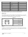
Display Drive:
The segment drive outputs of 8279 (A0 through A3 and B0 through B3) form a single 8-bit
parallel output driving the display element segments. The correspondence between the data bus,
segment outputs of 8279 and the display element segments is shown below :
TABLE 5.4
Display Segment
Control
a
f
b
CPU
g
D6 D5 D4 D3 D2 D1 D0
e
A1 A0 B3 B2 B1 B0
d
a
dp
g
f
c
dp
D7
DATA BUS
8279
A3 A2
Output
Segment d c
b
e
Enabled
Example:
Bit =1
Corresponding segment is ON
To display "E", the
datasegments
format requires that segment a,f,g,e
and d should be ON
display
=0 Corresponding
segments
be OFF. So the data should be 1001 0111=97H. Display codes
segment isshould
OFF
and other
for other
patterns can be worked out similarly.
__________________________________________________________________________________________
MPS 85-3 User‟s Manual
1 -47
Display Position:
To display characters in the address field, 8279 must be instructed to start from display position
0 (by sending 90H to the command port of 8279) and to display characters in the data field, 8279
must be instructed to start from display position 4 by sending 94H to the command port of 8279.
For further details regarding display codes and display procedures, user can refer the Monitor
Program Listing supplied along with MPS 85-3.
5.6 PROGRAMMABLE INTERVAL TIMER
MPS 85-3 has an on-board programmable interval timer 8253-5 at socket position U7. Its I/O
addresses can be found in Table 5.2 in section 5.4. 8253 has one command/status port and three
data ports called Timer0, Timer1 and Timer2 to provide three programmable timers. Of these,
Timer 0 is utilized to drive the TRAP input of the CPU, for implementing the Single Step
facility. SOD output from the CPU controls the gate input of this Timer 0. Timer 1 is utilized to
generate Transmit and Receive clocks of 8251A (Programmable Communication Interface).
However, these signals as well as the signals related to Timer 2 are available on system
connector J4. Thus, if user does not require serial interface, he/she can make use of Timer 1 (in
addition to Timer 2, which is always available to user) if required. Connector details are
provided in the last section of this chapter.
5.7SERIAL INTERFACE
An 8251A (Programmable Communication Interface) at position U9, is used for implementing
RS-232C compatible serial interface. This device is programmed for asynchronous operation, 2
stop bits, no parity, data length of 8 bits and baud scale factor of 16X. As already noted, Timer 1
of 8253 is used to generate the required Transmit and Receive clocks of 8251A based on the
setting of the DIP switch. (Refer section 2.1.2 on Baud selection).
The I/O address of 8251A can be found in Table 5.2 in section 5.4.
8251A is operated in a polled mode. However, character input routine can be made interrupt
driven by shorting JP6 A&B and writing suitable RST 6.5 service routine. (Refer section 2.1.4)
The TXD, RXD, CTS, RTS signals are given to MAX232(U10) to make an RS-232C
compatible. The RS-232C compatible signals are available on 9 pin D-type female connector J6.
(Refer the last section of this chapter for connector details)
NOTE: If the handshake signals are not required, user can short DTR, DSR and RTS, CTS.
__________________________________________________________________________________________
MPS 85-3 User‟s Manual
1 -48
5.8 PROGRAMMBLE PERIPHERAL INTERFACE DEVICES
MPS 85-3 has two numbers of 8255As (Programmable Peripheral Interface Devices). Each
8255A consists of a command port and three 8-bit programmable input/output ports called Port
A, Port B and Port C. The port addresses of these devices can be found in Table 5.2 in section
5.4. The two 8255As at U11 and U22 are completely available to user. The port signals are
available on connectors J2 and J1 (Refer the last section of this chapter for connector details.)
5.9 WAIT STATE LOGIC
MPS 85-3 accesses on-board memory and I/O devices with zero wait states. However, the
READY input to the CPU is available on system connector J3 and user can drive this signal low
to introduce wait states if required.
NOTE : READY is pulled up to VCC through a 4.7K ohm resistor on MPS 85-3.
5.10 INTERRUPTS AND HOLD
RST5.5, RST6.5 and RST7.5 inputs can be driven by either on-board signals 8279INT, RXRDY
and KBINT or by off-board signals RST5.5, RST6.5, and RST7.5 via connectors J3 and J4.
(Refer section 2.1.4). The system monitor does not make use of these vectored interrupts. Thus
while in the monitor, these interrupts are masked and disabled.
When these vectored interrupts are recognized, the CPU saves the PC and starts execution from
specific memory locations. To allow the use of these interrupts by the user, the monitor has JMP
instructions at these locations. The target of these JMP instructions is RAM area. For example,
when RST 7.5 is recognized, CPU pushes the current PC onto the stack and executes the
instruction at 3CH. The instruction at 3CH is JMP 8FBFH. Thus, now the control comes to
8FBFH. Three bytes are available to user from 8FBFH. Thus user should enter another JMP
instruction at 8FBFH (using for example, Examine Memory command) and this JMP must be to
the service routine written by the user. The RAM locations corresponding to different RST
instructions and vectored interrupts are shown below:
TABLE 5.5 RAM addresses for interrupts
Interrupt
Corresponding RAM location
RST 5.5
8FB3H
RST 6
8FB6H
RST 6.5
8FB9H
RST 7
8FBCH
RST 7.5
8FBFH
__________________________________________________________________________________________
MPS 85-3 User‟s Manual
1 -49
Chapter 8 on Programming Examples includes an example illustrating the use of RST 7.5
interrupt. In a similar way, user can make use of the other interrupts.
TRAP input is connected to Timer 0 output for single step implementation.
MPS 85-3 does not make use of HOLD signal. It is grounded through a 4.7K ohm resistor. An
off-board signal can drive this line via the connector J3. This can be done by opening the jumper
connection JP4 A- B and shorting JP4 B-C. As already noted in section 5.2, HOLDA from CPU
disables on-board buffers. Hence user can implement multiprocessor designs (for eg. DMA
systems ) without any problems.
5.11 BUS EXPANSION
MPS 85-3 permits easy expansion of the system by providing all the necessary signals on two
connectors, J3 and J4. The signals are STD bus compatible and thus user can easily expand the
capabilities of MPS 85-3.
5.12 CONNECTOR DETAILS
There are six connectors on MPS 85-3 in addition to the power connector J5. Four of them
(J1,J2,J3,J4) are 26 pin ribbon cable connectors. J1 and J2 are connected to parallel I/O lines
from two 8255s. J3 and J4 are used mainly for CPU expansion. 9-pin, female D-type connector
J6 provides the signals for RS-232C compatible serial interface.
The signal definitions on all these connectors are listed below. (This information is available in
Appendix B also).
CONNECTORS J1&J2
PIN NO
8255 PIN
FUNCTION PIN NO
8255 PIN
FUNCTION
ONJ1/J2
ON J1/J2
1
13
PC4
14
19
PB1
2
12
PC5
15
38
PA6
3
16
PC2
16
37
PA7
4
17
PC3
17
40
PA4
5
14
PC0
18
39
PA5
6
15
PC1
19
2
PA2
7
24
PB6
20
1
PA3
8
25
PB7
21
4
PA0
9
22
PB4
22
3
PA1
10
23
PB5
23
11
PC6
__________________________________________________________________________________________
MPS 85-3 User‟s Manual
1 -50
11
12
13
20
21
18
PB2
PB3
PB0
24
25
26
10
26
7
PC7
+5V
GND
CONNECTOR J3
PIN NO.
1
3
5
7
9
11
13
15
17
19
21
23
25
SIGNAL
BS0
RST 6.5
INTR
MOD IO/M*
BA15
BA13
BA11
BA9
VCC
BA7
BA5
BA3
BA1
PIN NO.
2
4
6
8
10
12
14
16
18
20
22
24
26
SIGNAL
BS1
KBRST IN
RDY
BHOLD
BA14
BA12
BA10
BA8
VCC
BA6
BA4
BA2
BA0
CONNECTOR J4
PIN NO.
1
3
5
7
9
11
13
15
17
19
21
23
25
SIGNAL
CLK1
OUT2
CLK2
RST 5.5
BIO/M*
ALE
BWR*
BRD*
GND
BD1
BD3
BD5
BD7
PIN NO.
2
4
6
8
10
12
14
16
18
20
22
24
26
SIGNAL
GATE1
GATE2
OUT1
GND
BCLK OUT
BRST OUT
BHLDA
BINTA*
GND
BD0
BD2
BD4
BD6
__________________________________________________________________________________________
MPS 85-3 User‟s Manual
1 -51
CONNECTOR J6
PIN NO.
1.
2.
3.
4.
5.
6.
7.
8.
9.
FUNCTION
GND
RXD
TXD
DTR
GND
DSR
RTS
CTS
NC
All the remaining pins are not connected in the above
J6 connector.
Note : If your terminal does not support handshaking
signals, loop RTS & CTS and DSR & DTR. Also
remember, MPS 85-3 TXD should be connected to
terminal RXD and so on.
__________________________________________________________________________________________
MPS 85-3 User‟s Manual
1 -52
CHAPTER
6
MONITOR ROUTINES
ACCESSIBLE TO USER
MPS 85-3 monitor offers several user-callable routines both in the keyboard and serial modes of
operation, details of which are given below. These routines can be used to considerably simplify
the program development work.
NOTE:
6.1
User should, as a general rule, save the registers of interest before calling the
monitor routines and restore them after returning from the monitor routines.
KEYBOARD MONITOR ROUTINES ACCESSIBLE TO USER
Calling
Address
Mnemonic
0440H
UPDAD
044CH
UPDDT
Functions
Updates Address field of the display. The contents of
the locations (CURAD), 8FEFH & 8FF0H are displayed
in the address field. The contents of all the CPU
registers and flags are affected. If Reg. B=1, dot at the
right edge of the field; if B=0, no dot.
Updates Data field of the display. The contents of the
location (CURDT),8FF1H are displayed in the data
field. The contents of all CPU registers and flags are
affected. If Reg. B=1, dot at the right edge of the field;
if B=0, no dot
__________________________________________________________________________________________
MPS 85-3 User‟s Manual
1 -53
0389H
OUTPUT
02BEH
CLEAR
04ADH
HILO
030EH
GTHEX
03BAH
RDKBD
034FH
HXDSP
0553H
RELCT
Outputs characters to display. The parameters for this
routine are as follows :
Reg A=0-Use address field
Reg A=1-Use data field
Reg B=1-Dot at the right edge of the filed.
=0-No dot.
Reg HL=Starting address of character string to be
displayed.
Clears the display. This routine blanks the entire
display field.
Parameter is:
Reg B=1 - dot at the right edge of the address field.
=0 - No dot.
Computes the difference between two 16-bit values.
Parameters are set up as follows:
Reg DE = Value 1;
Reg HL = Value 2;
The difference between the two values is available in
DE and carry is set as shown.
Carry = 1 if value 1 < Value 2
= 0 otherwise
DE = Value 1 - Value 2
Gets hex digits and displays them. This routine
collects the hex digits entered from the keyboard and
forms a 2 digit or 4 digit hex number.
Parameters: Reg B = 0
Display the received value in address field
=1 Display the received value in data field
Reads keyboard. This routine waits until a character is
entered from the system keyboard and upon return, it
places the character in the A register. The register A and
F/F's are affected.
Expands hex digits for display. This routine expands
hex digits and stores them in the specified buffer.
OUTPUT routine can now be used to display this
number,
parameters:
Reg DE = Hex value to be expanded.
Registers A,H, L and flags are affected.
Refer Section 8.4
__________________________________________________________________________________________
MPS 85-3 User‟s Manual
1 -54
6.2 SERIAL MONITOR ROUTINES ACCESSIBLE TO USER
Calling
Address
Mnemonic
0C12H
GETCH
0C2DH
SOUTPT
0C41H
NMOUT
0B88H
PRVAL
0B5BH
DISPM
0ABAH
GETHX
0B34H
HILOS
0BE4H
VALDG
Functions
Gets one character from the USART. Input parameters
None.
Output: C = Character (ASCII) received from USART.
Regs: A,C and flags are affected.
Outputs one character to the USART.
Inputs : C = Character (ASCII) to be output to USART.
Regs: A,C and flags are affected.
Outputs one byte as two hex digits to the Serial I/O
device.
Inputs : A = Byte to be output
Regs: A,B,C, and flags are affected.
Gets the ASCII code corresponding to a hex digit.
Inputs : reg C = Hex digit.
Outputs : C=Corresponding ASCII code.
Regs: B,C,H and L are affected.
Displays a string of characters. The string should be
terminated by character Zero which is not output.
Inputs: HL = Starting address of the string of
characters.
Regs: A,C,H,L, and flags are affected.
Gets 2 or 4 hex digits. Inputs: None
Outputs: Carry = 1 if valid hex value is received. Carry
= 0 otherwise.
D = Terminator Code.
BC = 4 hex digits or C= 2 hex digits. All registers are
affected.
Compares two hex values.
Inputs: DE = Hex value 1
HL = Hex value 2
Outputs: Carry = 0 if DE > HL
1 if DE <= HL
Only flags are affected
Checks if the character in register C is a valid hex digit.
Inputs : C=Character to be checked.
__________________________________________________________________________________________
MPS 85-3 User‟s Manual
1 -55
0800H
SERIAL
Outputs : Carry =1, if the character is a valid hex digit
(0-F)
Carry=0 otherwise.
Reg A and flags are affected.
Invokes serial monitor program.
__________________________________________________________________________________________
MPS 85-3 User‟s Manual
1 -56
CHAPTER
7
COMMUNICATION WITH A
HOST PC
7.1 INTRODUCTION
MPS 85-3 trainer kit is supplied with Windows and DOS driver packages, which allow the user
to establish communication between the MPS 85-3 trainer in serial mode and a Host PC through
its asynchronous communication ports (COM1/COM2/COM3/COM4, etc..). Both the packages
fully support the MPS 85-3 Serial Monitor commands including file upload and download
facilities. HEX files generated by PC native and Cross-tools can also be downloaded to the
trainer using these packages. Further, data from MPS 85-3 memory can also be uploaded to the
computer. The compatible serial cable for RS-232C communication is also included in the
package.
7.2 INSTALLATION
a)
Configure MPS 85-3 for serial mode of operation and set the serial port of MPS 85-3 for 9600 Baud rate and No
parity (Refer Chapter 2).
b). Connect the Host PC to MPS 85-3 over the serial COM port using the serial cable provided. (Refer to system‟s
Technical Manual for details regarding the signal definitions on COM ports (Refer appendix C of this manual for
serial cable details)).
7.3 INSTALLATION OF WIN853
WIN853 is a Windows based Communication package for MPS 85-3 trainer that provides a
powerful and convenient debugging and development environment to the user. The user must
install this software from the MPS 85-3 Drivers CD.
__________________________________________________________________________________________
MPS 85-3 User‟s Manual
1 -57
Insert the CD in the CDROM drive and run Setup.exe from the WIN853’s folder. The Setup
program will guide the user through the rest of the installation procedure. Once the Software is
installed successfully, WIN853 offers a complete online help for working with the commands.
Under WIN853, the trainer can communicate at a baud rate of up to 38400.
7.3.1 INSTALLATION PROCEDURE
1) Run Setup.exe from the Drivers Software CD. Now user can observe the following
dialog box, which will copy the required files from Source CD to the Host PC.
__________________________________________________________________________________________
MPS 85-3 User‟s Manual
1 -58
2) Click OK, then user can observe the following dialog box.
3) The default Installation directory will be C:\ProgramFiles\WIN853. User can change
the installation directory by clicking Change Directory.
4) Click the highlighted Icon shown above to continue the Installation Procedure, then
observe the following Dialog Box.
__________________________________________________________________________________________
MPS 85-3 User‟s Manual
1 -59
.
5) Select the Program Group, Default ESA Trainers. Click Continue, and then observe the following dialog box.
.
6) In some cases user will find the following Dialog Box, which will indicate the
over writing of the existing files.
__________________________________________________________________________________________
MPS 85-3 User‟s Manual
1 -60
.
7) Click Yes to keep the old file. Click No to install the new file. Click No to All for the
remaining files also.
8) Then finally observe the following dialog box, which will indicate the completion of
installation.
9) Click OK to complete the installation.
7.4 UNINSTALLATION PROCEDURE
1) Go to the Control Panel from Start Menu Settings. Select Add/Remove Programs
option. User will see the following Dialog Box.
__________________________________________________________________________________________
MPS 85-3 User‟s Manual
1 -61
2) Select the Driver to Uninstall, and click Add/Remove. Then the following dialog box will appear, which will ask
for confirmation.
.
3) Click Yes to uninstall, otherwise No to come out from the uninstallation procedure.
4) Delete the installation Directory manually(C:\Program Files\WIN853).
__________________________________________________________________________________________
MPS 85-3 User‟s Manual
1 -62
7.5 CONFIGURING THE INSTALLATION
1) Switch on the PC.
2) Connect the supplied RS-232C serial cable between the connector J6 (9 pin D-type female)
Trainer and COM port of the Host PC (9-pin D type male).
of the MPS 85-3
3) Power up the MPS 85-3 trainer using +5V DC power supply.
4) Set the baudrate for 9600 bps using the Dipswitches on the MPS 85-3 Trainer.
(Refer chapter 2).
5) Open the WIN853 application on the Host PC from the start button of the Microsoft
observe the following Dialog Box.
windows. Now user can
6) If the PC COM port is already set for COM1 and the baud rate set for 9600 bps, then click on „No’ button,
otherwise Click on „Yes’ button to change the setting of communication parameters. Then user will observe
the following dialog box.
.
7) Select the Baud rate as per the dipswitch configuration on MPS 85-3 Trainer. Select the
appropriate COM
Port configured in PC and Click on OK button. Now user can observe the following window.
__________________________________________________________________________________________
MPS 85-3 User‟s Manual
1 -63
.
8) In some cases , if the communication is not established user will get the error message dialog box as shown
below. In this case please check whether the MPS 85-3 Trainer is powered on. Check whether Serial cable is
connected properly between PC & MPS 85-3 Trainer and check the parameters by clicking the Settings.
.
__________________________________________________________________________________________
MPS 85-3 User‟s Manual
1 -64
9) If the communication is established properly, user can see the GUI of the application also
can communicate with the trainer serially. User can view the Register, Memory Dump,
Download, Upload, Run, single step, breakpoints, watch windows, Memory modification
icons etc…
Note:
Whenever the command window is full, it is recommended to clear the command window with “
CLS “ command. Otherwise display will become a bit slow.
7.6 OPERATION DETAILS
The complete command set of the MPS 85-3 is transparent and is fully supported by WIN853 (Refer chapter
4 for the monitor mode commands). Click on help icon in the WIN853 dialog box for help.
In addition, WIN853 supports the file download, file upload and other commands, which are explained
below.
NOTE: During parameter entry, the system expects the alphabetic characters to be in upper case. However,
WIN853 driver is not case sensitive. So, Keyboard with CAPSLOCK ON is not required.
7.6.1 DOWNLOAD OPERATION
This feature allows downloading the contents of an object code file into the memory of MPS 85-3.The object code
file must be a “. HEX” file with records in INTEL 8-Bit HEX format. Refer to the relevant INTEL manuals for the
definition of INTEL 8-Bit HEX format. Most of the cross assemblers for 8085 do produce object code files which
are
“. HEX” files with records in INTEL 8-Bit HEX format.
1) To perform download operation click on download button or go to file menu and choose
in the WIN853 dialog box. Then observe the following dialog box.
download option
__________________________________________________________________________________________
MPS 85-3 User‟s Manual
1 -65
2) Click on “Browse” tab, select the file which user wants to download and clock on “OK” button.
3) After downloading the program user can execute the program without entering command window also. For that
go to RUN menu and select SET PC option then observe the following dialog box
__________________________________________________________________________________________
MPS 85-3 User‟s Manual
1 -66
4) In that Set PC dialog box user can give the program starting address and click on OK
button. Now go to RUN menu and select RUN, then the program will execute and user
can see the output.
5) Otherwise go to view menu and select command window option, then user can find the following dialog box
__________________________________________________________________________________________
MPS 85-3 User‟s Manual
1 -67
6) Here user can give GO command to execute the program.
__________________________________________________________________________________________
MPS 85-3 User‟s Manual
1 -68
7.6.2 UPLOAD OPERATION
This feature allows uploading the data from the memory of MPS 85-3 to the computer and saves the data in the
specified disk file in INTEL 8-Bit HEX format.
1) To perform upload operation click on upload button or go to file menu and choose
upload option in the WIN853 dialog box. Now user can observe the following dialog box.
__________________________________________________________________________________________
MPS 85-3 User‟s Manual
1 -69
2) Click on “Browse” tab and give the file name to be saved, then user can find following dialog box. Here user can
select the path where the upload file should be saved.
__________________________________________________________________________________________
MPS 85-3 User‟s Manual
1 -70
3) After saving the file enter the starting and ending addresses of the file which is to be
and the upload dialog box as follows
uploaded and click on OK
4) Click on CANCEL button in the upload dialog box, after a successful uploading. If user wants to append the
memory to same uploaded file once again click on OK in the upload dialog box. Then user can find the
message as follows
__________________________________________________________________________________________
MPS 85-3 User‟s Manual
1 -71
5) Click on OK to append to previous file and click on CANCEL. After this operation user can download the
uploaded file as already mentioned above in the 10.6.1 session.
The following error messages may appear during upload and download due to improper operations.
1. File not found!
2. Path not found!
3. No more files!
4. Access denied!
5. Invalid file handle!
6. Insufficient Disk space!
7. Unable to continue upload!
8. Colon is not present at the start of the Record!
9. Invalid data in (source file) the following Record!
10.Checksum Error in the following Record!
__________________________________________________________________________________________
MPS 85-3 User‟s Manual
1 -72
7.6.3 COMMUNICATION
Communication parameters can be set during the session by pressing Ctrl+O or go to view menu and select options
in the WIN853 window. List of parameters and their current values will appear on the dialog box. Select the desired
parameter with the help of arrow keys. The parameters allowed to be set are Communication Port (suitable COM),
Baud Rate (110 /150 / 300/ 600 / 1200 / 2400 /4800 / 9600), Number of Data bits (7 or 8), Number of Stop bits (1or
2) and Parity (NONE/ODD/EVEN). After selecting the desired values click Ok in the following dialog box.
Otherwise click on CANCEL to ignore the values.
Table 7.1 shows details of the integer values and corresponding parameters.
Table 7.1
7.6.4 HELP
On-line help is available for all MPS 85-3 monitor commands and specific commands of WIN853. Get Help facility
by selecting help option in the window. A menu of commands are displayed from which the desired command can
be selected and associated information about that command is displayed. These options are explained in detail in
online help of WIN853 (WIN853.hlp).
Note: Whenever the command window is full, it is recommended to clear the command window with “ CLS “
command. Otherwise display will become a little bit slow.
TROUBLE SHOOTING:
1) Check the PC Serial Port working condition.
2) Check the Serial Cable working condition.
3) Check MPS 85-3 Trainer Kit for Sign on message.
4) Check the Dipswitch Settings.
__________________________________________________________________________________________
MPS 85-3 User‟s Manual
1 -73
CHAPTER
8
PROGRAMMING EXAMPLES
8.1 INTRODUCTION
In this chapter, we will describe some programming examples which can be run on the MPS 85-3
System. The first set of examples are designed to illustrate the use of various command keys and
the second set of examples are designed to illustrate the use of monitor routines. The user,
encountering a microprocessor trainer for the first time, is strongly urged to go through this
chapter in detail, load and execute the programs as indicated. The experienced user can skip this
section and directly refer to section 8.3 to become familiar with the use of monitor routines.
8.2 PROGRAMMING EXAMPLES
Example 1:
LOCATION
8800
8802
8804
8805
The following program is a very short and simple one. This program loads the
registers B and C with specific values and stores a specific value in a RAM
location. Assume the program is to be loaded from 8800 H. The program and the
hand assembly is shown below.
CONTENTS
06 22
0E 82
78
32 40 88
MNEMONIC
MVI B, 22H
MVI C, 82H
MOV A, B
STA 8840H
COMMENTS
;Initialize Reg B
;Initialize Reg C
;Load the RAM
location
8808
EF
RST 5
;Return control to the
monitor
Thus the sequence of 9 bytes to be stored from location 8800H through 8808H is - 06, 22, 0E,
82, 78, 32, 40, 88, EF. Enter these using EXAM MEM command. After entering the last byte
into the location 8808H, press the EXEC as the delimiter. Note that EXEC is only a delimiter
key and is not used for executing the user program. The command to be used for executing user
programs is the GO command. Using this command, execute the above program. After
__________________________________________________________________________________________
MPS 85-3 User‟s Manual
1 -74
execution, control returns to the monitor. Note that this happens because of the RST 5
instruction. When control returns to the monitor via the RST 5 instruction, the monitor first
saves the complete user context.
Now use the EXAM REG key to observe the contents of the registers B and C. They will be 22
and 82. Using the EXAM MEM command, observe the contents of the location 8840 H to be 22
H indicating the successful execution of the program.
Now press the RESET key and observe the contents of the locations 8808H and 8840H. The
contents remain undisturbed. Pressing the RESET key does not disturb the user portion of the
RAM. But now, examine the B and C registers. It is likely that they will not contain the values
22H and 82H. If you press the RESET key, user register values are not guaranteed to remain
unaltered.
Example 2: The following program converts two BCD digits stored in memory to a binary
number and stores the binary number in memory. It is assumed that the most significant BCD
digit is at the location 8840H and next BCD digit is in the next location i.e. in 8841H. The
equivalent binary number is to be stored in location 8842H.
The program first multiplies the most significant BCD digit by 10 and then adds the second BCD
digit to get the Binary number. The multiplication by 10 is implemented as repeated addition:
10 xa =(8xa) + (2xa) =[(4xa) + (4xa)] + (2xa)
BCDBIN:
MNEMONIC
LXI H, 8840H
COMMENTS
: Point to BCD string
MOV A, M
: Get most significant
: BCD digit
: MSD x 2
: Save it
: MSD x 4
:MSD x 8
: (MSD x 8) + (MSD x 2)
ADD
MOV
ADD
ADD
ADD
INX
ADD
A
B, A
A
A
B
H
M
INX H
MOV M, A
RST 5
: Add next BCD digit to get
: binary equivalent
: and store it
: Return to monitor
__________________________________________________________________________________________
MPS 85-3 User‟s Manual
1 -75
Suppose you decide to hand-assemble this program to start from location 8800H. Assume we
get the following sequence of bytes:
21,40,88,7E,87,47,87,80,23,86,23,77,EF. Enter these 13 (decimal) bytes into locations 8800H
through 880CH.
Set up two BCD digits in locations 8840H and 8841H - say 4 and 5.
Now execute the program using the GO command. After the execution of the program, control
returns to the monitor and a command prompt dash will be displayed. Now using EXAM MEM
command, examine the contents of the location 8842H. Surprisingly, instead of the expected
2D, we find 1D. So we should again check the program.
After going through the program again, we find the logic to be correct. The next step is to check
the coding. Now, we find (fortunately) that, while there are two ADD A instructions after MOV
B, A instruction, our code sequence has only one ADD A instruction. (After opcode 47H in
location 8805H, there should be 87H, 87H and then 80H; but we have only one 87H and then
80H). So instead of multiplying MSD by 10, we multiplied it by 6 (=4+2). To correct this, we
must insert an instruction of one-byte length (ADD A) at location 8807 H. We can use the
INSERT command for this purpose. The required key sequence would be INSERT <8800> `
NEXT <880C> NEXT <8807> NEXT <1> NEXT <87> EXEC.
Now using EXAM MEM command, observe the contents of the locations 8800H through 880DH
and verify that the program has been entered correctly. Now execute it. Examine the location
8842H. Fine, we get the correct result of 2D.
Example 3:
8085 has no instruction for multiplication. One simple way to implement multiplication is by
repeated addition. Here, if you want to multiply m by n, then you clear the result and add the
multiplicand m to the result n times, where n is the multiplier. Thus 2 x 3 is implemented as
[[(0+2) + 2] + 2] = 6. The following program multiplies any two one byte numbers, but assumes
that the numbers are unsigned.
Contents
Location
Label
Mnemonic
Comments
8800
0E, data1
MVI C, multiplicand
Initialize Reg C
8802
1E, data 2
MVI E, multiplier
Initialize Reg E
8804
21,00,00
LXI
Clear the HL Pair
8807
7B
MOV A,E
H, 0000H
Save the multiplier in A
__________________________________________________________________________________________
MPS 85-3 User‟s Manual
1 -76
8808
B7
ORA
A
multiplier
8809
CA, 13, 88
JZ
OVER
Yes : Jump to OVER
880C
06, 00
MVI B, 00H
clear B. This is done so that
DAD B
we can use DAD Ins
880E
09
880F
1D
8810
C2, 0E, 88
ADD : DCR E
JNZ
ADD
ADD multiplicant
Decrement multiplier
If multiplier is zero
MOV A, L
OVER : STA
9000 H
Jump to ADD.
8813
7D
Save the L content to ACC
8814
32,00,90
MOV A, H
Store the ACC content in 9000
8817
7C
STA
9001H
Save the H content to Acc
8818
32, 01, 90
RST
3
Store the Acc content in 900
881B
DF
Return to monitor.
Now, using the EXAM MEM command enter the above program. After entering the last byte in
to location 8810H, you press the EXEC key. Note that EXEC key is only a delimiter and it is
not a command to start the execution of user program. When you press the EXEC key, after
entering the last byte, the EXAM MEM command is terminated and monitor returns to the
command entry mode i.e. the display is cleared and a dash appears in the left most digit position
of the display.
Now we have to set up the parameters for this program. The parameters are the multiplicand and
the multiplier. Suppose, we select their values as 1AH and 1AH. They must be entered into the
registers E and C. Use EXAM REG command to enter these values.
Now, we are ready to execute the program. Note that if this program is part of a bigger program,
which usually will be the case, then the last instruction would have been a RET instruction. But
here, we write RST 3 instruction, so that control is returned to the monitor. Then, we can
examine the results. To start the execution of the program use GO key and provide the starting
address - 8800H.
__________________________________________________________________________________________
MPS 85-3 User‟s Manual
1 -77
Now the display is cleared, and E appears in the left-most digit of display. This always indicates
that a user program is running. But, now what is happening ? The `E' has remained there. We
know that when control returns to the monitor via RST 5 instruction, the monitor will display the
command prompt and sign-on message. This present program is extremely short one and should
not take more than a few milliseconds. Thus, E should be displayed only for a few milliseconds
and then a dash should appear. In fact, we should not be able to notice E at all, because it
appears for such a short period. Thus it is clear that the program is caught in infinite loop and
control is never returning to monitor. Now is the time for some debugging. The first thing to do
of course, is to recover from the erroneous program i.e. allow the monitor to gain control. The
only way to do it now would be to press the RESET key. (Note that this type of situation is
almost the only situation warranting the use of RESET key, once you initialise the system).
Now go through the code carefully to see if there are any coding mistakes. Assume we find one.
The next approach can be the single step command. So reinitialize the parameters (multiplicand
and multiplier) and use the single step command to step through the program. After executing
the first three instructions check the registers C, E, H and L and observe their contents to be O.K.
Now step through the next instruction. Reg A should be equal to the multiplier 1AH. It is! Now
step through the instructions until JMP instruction, checking the register contents after each
instruction. After stepping through the JMP instruction at the location 880CH, we come again
to the first instruction of the loop. Step through it. Now Reg A should contain 19H (1AH-1).
But what is it containing ? It is still 1AH though we have decremented the E register which is
holding the multiplier value. Checking E register shows that the multiplier has indeed been
decremented as Reg E now contains 19H. So the culprit must be the MOV A,E instruction. As
it is logically the correct instruction, the error must be one of coding and we must have done a
poor job while desk-checking the opcodes. Looking up the opcodes, we find that, indeed,
instead of entering 7BH (opcode for MOV A,E), we entered 79H (opcode for MOV A,C) in
location 8806H. Thus the multiplier is never found to be zero and an infinite loop occurs.
Correct this opcode and run the program again. Now it works.
This, rather trivial example was used only to illustrate the use of the single step command in
debugging the programs.
With experience, the user will certainly find many more ways in which the commands can be
combined to develop useful programs.
__________________________________________________________________________________________
MPS 85-3 User‟s Manual
1 -78
8.3
USE OF MONITOR ROUTINES
The user can considerably simplify his program development if he makes suitable use of the
several useful routines available in the system Monitor. Chapter 6 provides the descriptions and
calling addresses of such useful routines available in the keyboard monitor and in the serial
monitor.
The programming examples which follow, illustrate the use of monitor routines.
Example 4: This example waits for the user to press a key and then displays the corresponding
internal key code in the data field. The program is an infinite loop and to recover from this
program, you must press the RESET key.
NOTE: The keys RESET and KBINT are not connected to the keyboard controller. So the
program cannot recognize these two keys.
LOCATION
8800
8803
CONTENTS
CD,BA,03
57
LABEL
LOOP
MENMONIC
CALL RDKBD
MOV D,A
8804
8807
8809
CD,4F,03
06,00
3E,01
CALL HXDSP
MVI B,00
MVI A,01
880B
880E
CD,89,03
C3,00,88
CALL OUTPUT
JMP LOOP
COMMENTS
; Get the key code
; Reg D= Hex value to
; be expanded
; Expand the digits
; No Dot
; use data field for
; display
;Display the keycode
Enter this program using EXAM MEM command and execute it using GO command. Whenever
a key is pressed (any key other than RESET and KBINT keys), its internal keycode is displayed
and you can compare this value with the values shown in Table 5.2 (in chapter 5 on Hardware).
Example 5 :
If your objective is to display a numerical value only, as in the above example, a much simpler
way would be to use the routines UPDAD, UPDDT. The above program can be rewritten as
follows, if we use the routine UPDDT.
.
__________________________________________________________________________________________
MPS 85-3 User‟s Manual
1 -79
LOCATION
8800
8803
8805
CONTENTS
CD BA 03
06 00
32 F1 8F
8808
880B
CD 4C 04
C3 00 88
LABEL
LOOP:
MNEMONIC
CALL RDK BD
MVI B,00
STA 8FF H
CALL UPDDT
JMP
LOOP
COMMENTS
; Get key code
; No Dot
;Store key code in
;reserved location
;to Display it
Example 6:
This example flashes the two fields of display alternately. This program uses a subroutine to
produce delay between the displays.
LOCATION
8800
8802
8804
CONTENTS
3E 00
06 00
21 40 88
LABEL
AGAIN
8807
880A
880C
880E
CD 89 03
3E 01
0600
21 44 88
CALL
MVI
MVI
LXI
8811
CD 89 03
CALL OUTPUT
8814
8817
8819
881B
881E
8821
8823
8825
8828
CD 31 88
3E 00
06 00
21 46 88
CD 89 03
3E 01
06 00
21 4A 88
CD 89 03
CALL
MVI
MVI
LXI
CALL
MVI
MVI
LXI
CALL
DELAY
A,00
B,00
H, 8846H
OUTPUT
A,01
B,00
H,884AH
OUTPUT
882B
882E
8831
8834
8835
CD 31 88
C3 00 88
11 FF FF
1B
7A
CALL
JMP
LXI
DCX
MOV
DELAY
AGAIN
D, FFFFH
D
A,D
DELAY:
DLOOP:
MNEMONIC
MVI A, 00
MVI B,00
LXI H, 8840H
OUTPUT
A,01
B,00
H,8844H
COMMENTS
;Use address field
;No dot
;Use character string
;starting at location ;8840 H
;and display Fire
;Use data field
;No dot
;Character string
;starts at 8844 H.
;Display blanks in
;data field
;Introduce a delay
;Use address field
;No dot
;display HELP in
;address field
;Use data field
;No dot
;Message start
Display "US" in
; ;data field
;Introduce a delay
;Repeat the sequence
__________________________________________________________________________________________
MPS 85-3 User‟s Manual
1 -80
8836
8837
883A
B3
C2 34 88
C9
8840
0F 13 14 0E 16
16 10 0E 11 12
15 05
ORA E
JNZ
DLOOP
RET
ORG 8840H
DB 0F 13 14 0E
16 16 10 0E
11 12 15 05
Enter the program from 8800H to 883AH and enter the data from 8840H to 884BH, using the
EXAM MEM command. Using the GO command execute the program. You should see
alternate displays of the messages "FIrE", "HELP US". The delay between the messages can be
changed by altering the value initially loaded into D,E register pair, in the DELAY subroutine.
Example 7 :
This example illustrates the use of KBINT key. As explained in chapter 5 on Hardware, KBINT
key is connected to the RST7.5 pin of 8085 processor. (Jumper JP7 BC is shorted as factory
installed option) When this key is pressed, control is transferred to a prespecified location in
memory (3CH) as RST7.5 is a vectored interrupt. The monitor has a JMP 8FBFH instruction
starting at this location. Thus when KBINT key is pressed, control first goes to the location 3CH
and by executing the instruction there, comes to location 8FBFH. In this region also, there are
not many bytes available for a service routine, so we will write a further JMP at 8FBFH, to user
RAM area and in that area we must write the service routine.
The program described below is a random number generator. The main program consists of a
simple loop to increment a one-byte counter. The count after reaching FFH, become 0 again
with one further increment and thus is always a value between 0 and FFH. Whenever the user
presses the KBINT key, the interrupt service routine fetches the counter value, masks off the
most significant 6 bits, displays the value (thus the number displayed is always 00,01,02 or 03)
and returns to the main program which continues with updating the counter value.
LOCATION
8800
8802
8803
8804
8805
8806
CONTENTS LABEL
3E 0B
30
FB
AF
3C
LOOP:
C3 05 88
MNEMONIC
MVI A,0B
SIM
EI
XRA A
INR
A
JMP
LOOP
COMMENTS
;Initialise Interrupts
;Unmask RST 7.5
;Enable Interrupts
;Infinite loop of
;updating the counter
__________________________________________________________________________________________
MPS 85-3 User‟s Manual
1 -81
Notice that, we must first unmask RST7.5 interrupt using the SIM instruction and then we must
enable the Interrupt system using the EI instruction. Enter the above program using EXAM
MEM command.
Now, we must write the service routine. Assume we want to load it from 8820H. So we
must write a JMP 8820H instruction at location 8FBFH.
LOCATION
8FBF
CONTENTS
C3 20 88
MNEMONIC
JMP 8820
COMMENTS
;Jump to RST7.5 service routine
Enter these bytes using EXAM MEM command.
Now at 8820H, we must write the service routing.
LOCATION
8820
8821
8823
8826
8828
882B
882C
882D
CONTENTS
F5
E6 03
32 F1 8F
06 00
CD 4C 04
F1
FB
C9
LABEL
LOOP:
MNEMONIC
PUSH PSW
ANI
03
STA
8FF1H
MVI
B,00
CALL UPDDT
POP
PSW
EI
RET
COMMENTS
;save counter
;Mask off the most significant 6 bits
;No Dot
;Display the number
;Restore counter
;Enable interrupts
;Return to main program.
Notice the EI instruction, before the RET instruction. This is required, as interrupts are disabled
once an interrupt is recognized. As, we want to recognize the interrupts again, we must enable
them before returning to the main program. Load the above service routine.
Execute the program at location 8800H. Now whenever the KBINT key is pressed, a value
between 0 and 3 is displayed in the data field. As this program is an infinite loop, to recover,
you must press the RESET key.
Example 8:
This example illustrates the use of a serial monitor routine to display a message on the console.
In the following program it displays `ELECTRO SYSTEMS' on the console.
LOCATION
8800
8803
8806
8808
CONTENT
21 00 89
CD 5B 0B
0E 20
CD 2D 0C
MNEMONIC
LXI
H,8900H
CALL DISPM
MVI C,20
CALL SOUTPT
COMMENTS
;Start of the first message
;Displays the first word `ELECTRO'
;ASCII code for space
;Output it to USART
__________________________________________________________________________________________
MPS 85-3 User‟s Manual
1 -82
880B
880D
8810
8813
0E 20
CD 2D 0C
21 08 89
CD 5B 0B
MVI
CALL
LXI
CALL
8816
8900
8908
DF
RST 3
45 4C 45 43 54 52 4F 00
53 59 53 54 45 4D 53 00
C,20H
SOUTPT
H,8908H
DISPM
;ASCII code for space
;Output it to USART
;Start of the second message
;Displays the second word
`SYSTEMS'
;Return to monitor
Enter the program in locations 8800H to 8811H and data from 8900 to 890F using `S' command.
And using `G' command execute the program. Then `ELECTRO SYSTEMS' will be seen on the
console.
NOTE:
This program as well as the earlier programs can be entered using the Text Editor and assembled
using the resident Assembler. Disassemble the code using the Disassembler before executing the
programs to see the machine codes generated.
8.4
RELOCATION OF PROGRAMS
What is Relocation ?
Suppose you have a program assembled from a given location. If you move the program code to
a different location, generally it will not work properly. This is because of the fact that all jump,
call and direct load instructions will be having address references pointing to the old locations.
As an example consider the following DELAY subroutine.
LOCATION
8840
8843
8844
8845
8846
8849
OPCODE
01 FF 07
0B
78
B1
C2 43 88
C9
LABEL
DLY:
MNEMONIC
LXI
B,07FFH
DCX
B
MOV A,B
ORA C
JNZ
DLY
RET
If you move the above block of code to another location, say 8850H, then it will not work
correctly. The instruction at 8846H will be JNZ 8843 while it should be JNZ 8853 as the value
of the label DLY is now 8853H. All such address references must be adjusted appropriately, for
__________________________________________________________________________________________
MPS 85-3 User‟s Manual
1 -83
the moved program to work properly. Such a process of adjustment is called Relocation. (Of
course this is a simplistic view, but adequate for the present discussion).
Such a relocation feature is an extremely convenient tool for debugging. As an example suppose
you want to debug a program located in a PROM. As the program is in a PROM, you can't
conveniently introduce any code patches to try out alternatives. If you can relocate such a
program into RAM area, it will be a simple matter to introduce the necessary code patches. This
is just one example. There are many other situations where a Relocation facility can be put to
good use.
MPS 85-3 provides the user with a convenient tool for such a relocation. This is done through a
monitor routine RELCT whose calling address is 0533H. Now we describe the use and
limitations of this routine.
Using the Relocation routine RELCT To use this routine, the following parameters must be set
to appropriate values:
Memory Location
8FE9 , 8FEA
8FEB , 8FEC
8FED , 8FEE
8FE5 , 8FE6
8FE7 , 8FE8
Parameter Description
Relocation offset (OFSTAD)
Relocation offset = New starting Address Present starting address.
Starting address of the program (LOLMT)
Ending address of the program (HILMT) (All
the instructions between the starting address
and ending address are relocated)
Low-Limit of the range (SADD1)
High-Limit of the range (DADD1) (All
memory references to the addresses which are
within this range are adjusted)
Operation of RELCT routine.
This monitor routine will examine each instruction, from starting address to ending address. If
the instruction is not a memory reference instruction, it will proceed to examine the next
instruction. On the otherhand, if it is a memory reference instruction, then it will check if the
referred address is within the range Low-Limit, High-Limit. If it is out of range the instruction is
not disturbed. Otherwise, the Relocation offset is added to the reference address of this
instruction. For example, assume the instruction is 78H (MOV A,B). It will be left undisturbed.
Suppose the instruction is C2,43,88 (JNZ 8843H) i.e. a memory reference instruction. Suppose
the Low Limit is 8840H and High-Limit is 8849H. Then 8843 is within this range. Now assume
__________________________________________________________________________________________
MPS 85-3 User‟s Manual
1 -84
that the offset is 0010H. Then it will add 0010H to 8843H and this new value of 8853H will
replace 8843H. Thus the instruction will now appear as C2,53,88. This process is repeated with
all the instructions from Start address to End address.
NOTE:
All three byte instructions are of memory reference type, but for the following 4 instructions;
LXI B, Value; LXI D, Value; LXI H, Value; LXI SP, Value.
Steps involved in using the RELCT routine
In summary the steps involved in using the RELCT routine are as follows:
Step 1: Use the Block Move command to move the program code from the original area to the
desired area.
Step 2: Set up the parameters required for the RELCT routine as explained above.
Step 3: Find 4 bytes of free RAM area and enter the following program.
CALL
RST
RELCT
5
; Call the monitor routine to
relocate the code
; Return to monitor
Step 4: Execute the above program using the GO command.
Step 5: If required, alter addresses which are not memory references, if any.
Example 9:
Consider the following simple subroutine which implements a delay. (Assume the program is
assembled from 8840H).
LOCATION
8840
8843
8844
8845
8846
8849
CONTENTS
01 FF 07
0B
78
B1
C2 43 88
C9
LABEL
DLY:
MNEMONIC
LXI B,07FFH
DCX B
MOV A,B
ORA C
JNZ DLY
RET
__________________________________________________________________________________________
MPS 85-3 User‟s Manual
1 -85
Let us assume that we want to relocate this program to the address 8850 H. As already noted the
first step is to move the code using the BLOCK MOVE command. The required key sequence is
BLKMOVE <8840> NEXT <8849> NEXT <8850> EXEC
Note that the locations 8856, 8857 and 8858 contain the values C2,43,88. Thus the target
address of this "JNZ" instruction is incorrect. It should be 8853 and not 8843. Hence this value
must be adjusted suitably. In a larger program, there might be several such memory references
which have to be adjusted. This can be done conveniently by using the routine
RELCT.
We have to now set up the parameters for the RELCT routine as shown below.
Relocation offset:
As we want to move the program from 8840H to 8850H, the offset is 8850 - 8840 = 0010H.
Starting address = 8850H (and not 8840H)
Ending address = 8859H (and not 8849H)
Low-Limit and High Limit:
As the original program contains reference to addresses in the range 8840-8849H, we have to
specify this range for our relocation, so :
Low-Limit = 8840H
High-Limit = 8849H
Enter these parameters into the appropriate memory locations using the EXAM MEM
Command.
Now we must `CALL' the RELCT routine. For this purpose, we have to write small program.
Find 4 bytes of unused RAM area (say 8C00- 8C03H) and enter the following program and
execute it using the GO command.
LOCATION
8C00
8C01
8C02
8C03
CONTENTS
CD
53
05
EF
COMMENTS
;Call the Relocate Routine
;Return to monitor
__________________________________________________________________________________________
MPS 85-3 User‟s Manual
1 -86
Now you can use EXAM MEM command to examine the locations 8850- 8859H and verify that
indeed the program has been relocated. (8857H location will contain 53H and not the incorrect
43H).
Note that RELCT routine will adjust only memory references. This may necessiate further
adjustments as shown in the following example.
Example 10:
Consider the following program which outputs 4 characters stored in a table to the
keyboard/display controller 8279.
LOCATION
8800
8803
8805
8806
8808
8809
880A
880D
880E
CONTENT
21 0E 88
0E 04
7E
D3 30
23
0D
C2 05 88
EF
37 37 60 E3
LABEL
D10:
MNEMONIC
LXI H,880EH
MVI C,04
MOV A,M
OUT DAT79
INX
H
DCR C
JNZ D10
RST 5
DB:37H,37H,60H,E3H
Assume you want to relocate the program to start from 8820H and you want to move the
program as well as the table of 4 bytes which starts at 880E H.
Now if you use BLKMOVE command, then write the program fragment to relocate as in
Example 9, you will have all memory references properly adjusted. But the first instruction will
still be 21 0E 88. In otherwords, though the table has been moved from 880EH to 882EH, the
value loaded into H,L register pair will remain unaltered. This is because of the fact that, as
already noted, RELCT routine adjusts only memory reference address and the instruction LXI H,
value does not involve memory reference. Hence you have to adjust such values after relocation.
Summarizing the example, if constant data is being moved, reference to such data items must be
adjusted by the user.
__________________________________________________________________________________________
MPS 85-3 User‟s Manual
1 -87
CHAPTER
9
EDITOR – ASSEMBLER
9.0 INSTALLATION PROCEDURE
Set MPS 85-3 trainer in serial mode operation at baud rate 9600 (default) by keeping the
switch 4 of 8-way DIP switch ON-Position.
Connect one end of RS-232C cable to trainer and the other end to a host PC (terminal) for
serial communication. Execute the WIN853 software or any terminal emulation software.
Switch-ON Power supply to trainer then the sign on message “MPS-85 SERIAL MONITOR
Vx.y” will be displayed on the WIN853 Command window.
Execute the program from 2000H using „GO‟ command then the following menu will be
displayed on the WIN853 Command window.
MPS-85 Editior-Assembler System Vx.y
E =
D=
A=
X=
Editor
Disassembler
Assembler
Exit
E/D/A/X ?
“X” exits editor – assembler and returns to the Serial Monitor.
The detailed explanation of each module is given under the corresponding sub-heading.
__________________________________________________________________________________________
MPS 85-3 User‟s Manual
1 -88
9.1 EDITOR
If “E” is typed, the editor module is invoked.
9.1.1 Main Features
This is a text editor with full text editing facility that includes Insert, Delete, List, Replace, and
Exit commands. It also supports loading programs from an audio cassette tape and saving an
edited text onto the tape. The editor requires the length of the line to be a maximum of 72
characters and the lines are terminated by end of line marker – 0DH. The end of file marker is a
1AH.
While loading from a tape, if the EOL – EDF marker combination is not present at the end of the
file, then the file cannot be opened.
At sign-on the following message is displayed.
MPS-85 Text Editor Vx.y
D = Delete
I = Insert
L = List
R = Replace
X = Exit
If user wants to load a text file from the audio cassette then respond to the LOAD prompt with
the name of the file followed by a <CR> (the audio cassette interface player is installed prior to
this). Now depress the PLAY key on the cassette player. After loading the text the file
parameters and the Editor prompt will be displayed.
Starting Address =
Ending Address =
SSSS
EEEE
Buffer End =
Now the user can specify a value greater than the present file end address for future expansion
while editing. But a response of <CR> only will not allow the user to expand the file while
allowing other editing features.
In case you do not want to load from the audio cassette then it can be skipped by a <CR>.
__________________________________________________________________________________________
MPS 85-3 User‟s Manual
1 -89
Text Buffer [9000-A7FF]
Starting Address =
Now type in the Starting address of the buffer, the system will respond with
Ending Address =
Now type in the Ending address of the buffer. Then the system will enter the editor mode with
the editor prompt “>” displayed on the next line.
NOTE : The default value for the buffer start and end is enclosed in the brackets and can be
chosen by skipping both the prompts.
“>” is the Editor command prompt. The individual commands with the proper syntax are
explained as follows.
Insert Syntax : I or I# or I in
“I” Command allows you to insert at the beginning of the file. If the file is opened for the first
time the following message is displayed.
NEW FILE
0001
Where “0001” is the first line number.
“I#” command lets you insert at the end of the file.
“I in” command inserts just before the line specified by the line number parameter “in”
NOTE : a) The line number gets increment by one every time a <CR> is executed.
b) “CTRL-A” aborts the current line and terminates Insert mode and reenter back to
the Editor command.
List Syntax : L or L1n or L 1n1, 1n2
“L” command display the content of the complete file.
“L 1n” command display the line specified the : 1n” parameter.
__________________________________________________________________________________________
MPS 85-3 User‟s Manual
1 -90
“L 1nl, 1n2” command displays all the lines starting from line, 1n1 to line, 1n2.
The display scrolling can be halted at any point by CTRL-S and restarted by any other key. The
listing can be aborted at any time by CTRL-C.
Delete Syntax : D 1n or D1n1, 1n2
D 1n” command deletes the line specified by the line number parameter “1n” D1n1, 1n2
command deletes all the lines starting from line, 1n1. to line, 1n2
NOTE :
a) If the “1n2” parameter is greater than the total number of lines, then “1n2” takes the value of
the last line number.
b) At the end of deletion, the following message is displayed.
N – LINES DELETED
Where “n” is the number of lines deleted.
Replace Syntax : R 1n
This command lets the user replace the contents of an existing line specified by the parameter
“1n”, with the new contents. At the execution of the command the following format is
displayed.
1n … the present content of the line
1n
Now the new content can be typed and executed with a <CR>
NOTE : The old content can be retained at any stage if <CR> is executed without typing any
character
Exit Syntax : X
The Editor first display the current file name maintained in the buffer.
FILE NAME = XXXX
__________________________________________________________________________________________
MPS 85-3 User‟s Manual
1 -91
This can be optionally changed by typing in a new file name. Otherwise only <CR> will retain
the old file name.
Then it displays the current parameters of the previous buffer area
Starting Address =
Ending Address =
SSSS
EEEE
This will be followed by the following prompt
SAVE? (Y/N)
Responding with “Y” will save the buffer content in the cassette tape. (Audio tape interface
must be connected externally to the trainer and Recording keys to be depressed before selecting
this option). Typing “N” will take you out of the Editor to the main menu.
9.1.2 ERROR DESCRIPTION
Bad Command
This occurs when the command is not recognised. This may also occur when user tries to
operate on lines that do not exist or give a list command when the buffer is empty.
Tape Error
This occurs when the file on the audio tape has got corrupted.
9.2
DISASSEMBLER
9.2.1 Main Features
This module is invoked if user choice is “D” from the main menu. The following sign-on
message is displayed with the prompt.
MPS-85 Disassembler Vx.y
Program
Starting Address =
Type in the starting address for the assembled code that has to be disassembled. Now user will
be prompted with
__________________________________________________________________________________________
MPS 85-3 User‟s Manual
1 -92
Ending Address =
After user typed in the ending address it will prompt you for the Label starting address as
Label Table [A800-AFFF]
Starting Address =
And this will be followed by the prompt for the ending address
NOTE :
1. If the ending address <starting address it will prompt you all over again.
2. The default location of the label table is enclosed in the brackets.
After the correct data for the above are given, system starts execution and display the following
message.
Starting Pass 1
And then followed by the message
Starting pass 2
Then it displays the display column headers as
ADDRESS
CODE
LINE
LABEL
MNEMONIC
OPERAND
The disassembler code is then displayed according to the above format.
The display can be halted at any point by CTRL-S and restarted by typing any other key.
At the end it will display
End of Disassembly
And the control will be returned to the main menu.
__________________________________________________________________________________________
MPS 85-3 User‟s Manual
1 -93
9.2.2 ERROR DESCRIPTION
Label Table Exhausted
This is displayed before the start of pass – 2 when the number of labels is greater than what can
be accommodated in the label table. The pass-1 is aborted as soon as this occurs, but Pass –2
goes on with some of the internal references going unlabelled. This message stays on the screen
for 75 seconds and Pass 2 starts thereafter.
Invalid code _______ ________ @__________ H
This is displayed if a invalid opcode is encountered with the message listing the illegal opcode
and its location. This message is first displayed in Pass – 1 and aborts it and it is again displayed
in Pass-2 with the Disassembly aborted thereafter.
9.3 ASSEMBLER
If the user types “A” from the main menu the assembler signs-on as :
MPS-85 Assembler Vx.y
9.3.1 Main Features :
This is a two pass assembler which supports a powerful set of assembler directives, that enhances
the use of the MPS 85-3 microprocessor trainer towards a complete and thorough understanding
of the 8085 microprocessor and its programming concepts. The assembler also supports a
sufficient range of expressions.
The assembler prompts for the start and the end of the source-text buffer and also that for the
symbol table as :
Text Buffer [9000-A7FF]
Starting Address =
Ending Address =
Label Table [A800-AFFF]
Starting Address =
Ending Address =
__________________________________________________________________________________________
MPS 85-3 User‟s Manual
1 -94
The values shown enclosed within the square brackets [ ], are the default values and are chosen
when no values are entered and a <CR> is typed. At the end of the above prompt, the assembler
begins the assembly.
After the initialization process, the assembler also checks if the source file is a proper text file or
not, i.e, occurrence of the end of the file marker 1AH followed by end of line marker 0DH. The
processing is completed at the first occurrence of such a combination.
The symbol table is created and most of the errors are checked for and detected during the Pass1, the start of which indicated by the following message.
Starting Pass –1
This is followed by the message :
Starting Pass –2
Which indicates the termination of the Pass-1 and the start of the Pass-2. Any error that was
found in a line during the Pass-1 is noted and the error code stored. This enables the assembler
to skip those lines for further processing.
During the Pass-2, the ultimate codes are generated and loaded at the specified location as per
the ORG directive or the RORG directive. The value of the location counter, the codes, the line
number and source line is displayed along with the error code for that line if any. The format of
the displayed lines is as shown below.
ELLLL CCCCCC
NNNN Source Line
Where,
E
LLLL
CCCCCC
NNNN
Source Line
is the error code if any
- is the current value of the location counter
- are the object codes generated and loaded
- is the current line number
- is the complete source line
The code field – CCCCCC is blank if there is an error in the line, and the location counter is not
affected by its presence.
__________________________________________________________________________________________
MPS 85-3 User‟s Manual
1 -95
The display can be halted at any point by CTRL-S and restarted by any other key.
At the end of the assembly the control is transferred back to the main menu.
9.3.2 Expression Syntax
The assembler allows expressions with a maximum of two terms separated by the following
symbols that allow arithmetic operation like addition, subtraction, multiplication and division
respectively.
+ - * /
The terms separated by the arithmetic operators can either be a label or a number. The number
must be followed by the number system identifier (except in the case of a decimal number where
the absence of an identifier also signifies decimal number). The identifier allowed are the
following
B – Binary number
O – Octal number
D – Decimal number
H – Hexadecimal number
In the case of binary numbers, the last 16 binary digits are evaluated. For decimal and the
hexadecimal numbers, the last 4 digits are considered, whereas in the case of octal numbers the
last 5 digits are taken into account.
Example of valid expressions.
LABEL1* 110101110001101101B
LABEL/LABEL2
110111B+8642H
1234H – 123D
1000 * LABEL 1
Examples of invalid expression
LABEL1*
Presence of a operator without the second term
1211B
“2” is not a binary digit
1210T
number system not recognised
LABEL1\LABEL2 arithmetic operator not recognised
1015 LABEL1
missing arithmetic operator
__________________________________________________________________________________________
MPS 85-3 User‟s Manual
1 -96
1234d*10H+1101B
more than two terms in the expression
If the label is undefined then an expression error occurs.
9.3.3 Syntax of the Source Line
a) Label Field
The length of the label has been restricted to 6 (six) to save the limited address space for the
symbol table. The characters allowed in the label are :
A-Z and 0-9
In addition to this “?” And “@” symbols are allowed as the first character only
Also the label should not start with a numeral (0-9)
The label should be followed immediately by a colon ( : )
Even mnemonic names can be used in the label field.
There is no restriction as to its placement
Dummy labels are also allowed.
b) Mnemonic Field
The mnemonic or the pseudo-opcodes can be placed immediately after the colon ( : ) or after the
label if a label is present or it can be placed anywhere.
c) Operand Field
The operand can also be placed anywhere and there can be tabs and spaces between the different
segments of the operand.
d) Comment Field
The field is distinguished from the others by a semicolon (;) preceding it. Any character after the
first occurrence of the semi-colon, including the semi-colon is not processed and is considered as
a part of the comment.
9.3.4 Assembler Directives
a) ORG Origin
__________________________________________________________________________________________
MPS 85-3 User‟s Manual
1 -97
Syntax : ORG expression
This directive defines the location counter, with respect to which the lines following this
statement are to be assembled.
With the absence of this, the location counter takes the starting default value of 0000H
Multiple ORG statements are allowed.
b) RORG Relocatable origin
Syntax : RORG expression
This defines the loading pointer, with respect to which the object codes will be loaded.
The loading pointer takes the value of the location counter if no RORG statement is present.
Multiple RORG statements are not allowed.
c) DS Define Storage
Syntax : Label : DS expression
With this directive, the assembler allocates free spaces in the memory, the number of bytes
allotted is evaluated from the “expression”.
The location counter and the loading pointer are incremented by the value of the expression.
d) DB Define byte
Syntax : Label : DB expression
OR
Label : DB “ASCII string”
Using this a specific byte or a string of ASCII characters can be loaded into the memory.
The “expression” should evaluate to a value less than or equal to 0FFH, ie. Of one byte length.
e) DW Define word
__________________________________________________________________________________________
MPS 85-3 User‟s Manual
1 -98
Syntax : Label : DW expression
OR
Label : DW “Two ASCII characters”
This allows loading of two bytes into the memory with the lower byte being loaded first always.
f) SET Set label to value
Syntax : Label : SET expression
Here the label will be given a value obtained from the expression.
This value is temporary and can be changed temporarily again by another SET statement or set
permanently by a EQU directive.
The label shouldn‟t have been defined earlier through anything else other than another SET
statement.
g) EQU Equate label to value
Syntax : Label : EQU expression
This differs from the SET directive in the fact, that the label that has been defined by a SET
directive temporarily, can be defined permanently by this statement.
Any label that has been defined earlier by any means except by a SET statement cannot be
defined again by this statement.
h) END End assembly
Syntax : END
This instructs the assembler to end processing at the end of the two passes.
The assembler inserts an END statement at the end of the file if it is missing.
9.3.5 ERROR DESCRIPTION
I)
Error Messages
__________________________________________________________________________________________
MPS 85-3 User‟s Manual
1 -99
1.
In the case of the number of errors during the Pass-1 exceeding 85 (eighty five), the
normal assembler display format is changed and only an error listing is produced that
includes only invalid lines detected during the Pass-1. The Pass-2 is not started at all and
the assembly is aborted.
2.
If the file doesn‟t contain the EOL-EOF marker sequence (0DH followed by 1AH), then
it displays
IMPROPER FILE !
And aborts assembly
3.
If the END statement is absent, then it displays
Missing END statement!
at the end of Pass-1 and carries on to the Pass-2. This is not a fatal error.
4.
If the symbol table space is not sufficient and the label space gets exhausted, then the
message
Label Table Exhausted! is displayed and the assembly is aborted with only the partially
completed error listing displayed.
II)
ERROR CODES
a) “E” – Expression Error :
This error occurs when the expression cannot be evaluated due to reasons like :
The digit doesn‟t confirm as the correct digit for the number system implied.
Number system other than Binary, Octal, Decimal and Hexadecimal is implied.
Incorrect mathematical operator i.e. other than addition (+), subtraction (-), multiplication (*)
or division (/)
Undefined label
Number of segments in the expression is more than two.
Missing mathematical operator
Only one segment in the expression through a mathematical operator is present
__________________________________________________________________________________________
MPS 85-3 User‟s Manual
1100
b) “S” – Syntax Error :
This is an error that occurs when the syntax of the source line is improper due to reasons like :
Too long a label
Illegal characters in the label field
Illegal mnemonic
Illegal pseudo-opcode
Missing label field for pseudo-ops like SET and EQU
Missing operand field for some mnemonics and pseudo-ops
Incomplete operand field.
The expression evaluates to a value greater than 1 Byte for immediate instruction allowing
only 1 Byte data.
c) “ M’ – Multiple Definition Error :
This is caused due to the following reasons
The same label has been used to define something else earlier except by means of a SET
directive.
The label is being defined by a SET directive after it has been defined earlier by means other
than through the SET directive
__________________________________________________________________________________________
MPS 85-3 User‟s Manual
1101