1
CCII Systems (Pty) Ltd Registration No. 1990/005058/07
C ommunications
C omputer I ntellig ence
I nteg ration
User Manual
for the
PMC High-Speed Serial VxWorks Driver
C²I² Systems Document No.
CCII/HSS/6-MAN/002
Document Issue
4.1
Issue Date
2009-05-27
Print Date
2009-05-28
File Name
P:\HSS\TECH\MAN\CHSMAN02.WPD
Distribution List No.
© C²I² Systems The copyright of this document is the property of C²I² Systems. The document is issued for the sole
purpose for which it is supplied, on the express terms that it may not be copied in whole or part, used by
or disclosed to others except as authorised in writing by C²I² Systems.
Document prepared by C²I² Systems, Cape Town
Amendment History
Issue
Description
Date
ECP No.
1.0
Initial version created by splitting cManSioDrv.wpd, Issue 1.1
into separate SIO and HSS user manuals.
2000-03-16
-
1.1
Updated Application Program Interface (API) to correspond
with version 1 release 0 of the host driver.
2000-05-23
-
2.0
Updated for HSS version 2.0.
2000-06-06
-
2.1
Updated paragraph 4.2, detailing protocol structures and
setup options.
2000-10-31
-
2.3
Updated driver data structures to include DPLL and various
encoding methods.
2001-01-19
-
2.4
Added version display function for driver and firmware
software. Updated UART and HDLC descriptions. Added
clock detection function.
2001-03-19
-
2.5
Added functionality to attach external clocks. Added SMC
ports.
2001-04-23
-
2.6
Implemented the BISYNC protocol. Included the BIT
functions descriptions. Added configuration specifics for the
X86.
2001-05-21
-
2.6.1
Added HSS Front Panel functionality.
2001-06-15
-
2.6.2
Changed flash programming.
2001-07-05
-
3.0
General update of driver.
2001-09-13
-
3.1
Updated description of include-files.
2001-09-25
-
3.2
HSS Serial I/O back & front panel boards share the same
protocol information structure now. Updated description of
protocol information structure.
2001-10-01
-
3.3
Added new hssOpen_port_fp() function, which allows for
floating point initialisation of send, receive and clock tasks.
2001-10-12
-
3.4
Added new hssCreate_device_ex() function, which allows the
user to specify the Rx & Tx buffer size for each port.
2002-01-17
-
3.5
Updated call-back function description: added CRC error and
Tx done error reporting.
Updated BIT structure: added oscillator frequency variable.
2002-04-11
-
Changed format of document according to latest company
template.
Update to BIT structure.
Added description for Low Latency (Polled Mode) driver.
Added description for High Speed Mode for Serial Port A.
2003-03-25
CCII/HSS/6-ECP/002
4.0
Added POST descriptions.
2003-08-27
CCII/HSS/6-ECP/009
4.1
Updated title of document.
2009-05-27
CCII/BLPGEN/6-ECP/015
3.5.4
CCII/HSS/6-MAN/002
CHSMAN02.WPD
2009-05-27
Issue 4.1
Page iii of vi
Contents
1.
Scope . . . . . . . . . . . . . . . . . . . . . . . . . . . . . . . . . . . . . . . . . . . . . . . . . . . . . . . . . . . . . . . . . . . 1
1.1
1.2
2.
Applicable Documents . . . . . . . . . . . . . . . . . . . . . . . . . . . . . . . . . . . . . . . . . . . . . . . . . . . . . 3
2.1
2.2
2.3
3.
Specifications . . . . . . . . . . . . . . . . . . . . . . . . . . . . . . . . . . . . . . . . . . . . . . . . . . . . . . . . . . . . . . . . . . . . . . . . 3
Standards . . . . . . . . . . . . . . . . . . . . . . . . . . . . . . . . . . . . . . . . . . . . . . . . . . . . . . . . . . . . . . . . . . . . . . . . . . . 3
Other Documents . . . . . . . . . . . . . . . . . . . . . . . . . . . . . . . . . . . . . . . . . . . . . . . . . . . . . . . . . . . . . . . . . . . . . 3
Installation Procedure . . . . . . . . . . . . . . . . . . . . . . . . . . . . . . . . . . . . . . . . . . . . . . . . . . . . . . 4
3.1
3.2
3.3
4.
Identification . . . . . . . . . . . . . . . . . . . . . . . . . . . . . . . . . . . . . . . . . . . . . . . . . . . . . . . . . . . . . . . . . . . . . . . . . 1
Introduction . . . . . . . . . . . . . . . . . . . . . . . . . . . . . . . . . . . . . . . . . . . . . . . . . . . . . . . . . . . . . . . . . . . . . . . . . 1
To Build the HSS Driver into the VxWorks Kernel . . . . . . . . . . . . . . . . . . . . . . . . . . . . . . . . . . . . . . . . . . . . 4
3.1.1 Tornado 1.0.1 Environment . . . . . . . . . . . . . . . . . . . . . . . . . . . . . . . . . . . . . . . . . . . . . . . . . . . . . . 4
3.1.2 Tornado 2.0 Environment . . . . . . . . . . . . . . . . . . . . . . . . . . . . . . . . . . . . . . . . . . . . . . . . . . . . . . . . 4
To Load the Driver Software Separately . . . . . . . . . . . . . . . . . . . . . . . . . . . . . . . . . . . . . . . . . . . . . . . . . . . 4
Using the HSS Driver . . . . . . . . . . . . . . . . . . . . . . . . . . . . . . . . . . . . . . . . . . . . . . . . . . . . . . . . . . . . . . . . . . 5
3.3.1 Overview of the HSS Driver . . . . . . . . . . . . . . . . . . . . . . . . . . . . . . . . . . . . . . . . . . . . . . . . . . . . . . 5
3.3.2 Creating the Device . . . . . . . . . . . . . . . . . . . . . . . . . . . . . . . . . . . . . . . . . . . . . . . . . . . . . . . . . . . . 7
3.3.3 Configuring the Ports . . . . . . . . . . . . . . . . . . . . . . . . . . . . . . . . . . . . . . . . . . . . . . . . . . . . . . . . . . . 7
3.3.4 Adding Receive Buffers . . . . . . . . . . . . . . . . . . . . . . . . . . . . . . . . . . . . . . . . . . . . . . . . . . . . . . . . . 7
3.3.5 Adding Call-back Functions . . . . . . . . . . . . . . . . . . . . . . . . . . . . . . . . . . . . . . . . . . . . . . . . . . . . . . 8
3.3.6 Sending and Receiving Data . . . . . . . . . . . . . . . . . . . . . . . . . . . . . . . . . . . . . . . . . . . . . . . . . . . . . 9
3.3.7 Destroying the Device . . . . . . . . . . . . . . . . . . . . . . . . . . . . . . . . . . . . . . . . . . . . . . . . . . . . . . . . . . 9
3.3.8 Detecting an active clock signal on ports . . . . . . . . . . . . . . . . . . . . . . . . . . . . . . . . . . . . . . . . . . . . 9
3.3.9 Obtaining the current host and firmware version number . . . . . . . . . . . . . . . . . . . . . . . . . . . . . . . 10
3.3.10 HSS Built-In-Tests . . . . . . . . . . . . . . . . . . . . . . . . . . . . . . . . . . . . . . . . . . . . . . . . . . . . . . . . . . . . 10
3.3.11 Low Latency (Polled Mode) Setting . . . . . . . . . . . . . . . . . . . . . . . . . . . . . . . . . . . . . . . . . . . . . . . 10
3.3.12 High Speed Mode Setting for Port A . . . . . . . . . . . . . . . . . . . . . . . . . . . . . . . . . . . . . . . . . . . . . . 11
3.3.13 HSS Power-On-Self-Tests . . . . . . . . . . . . . . . . . . . . . . . . . . . . . . . . . . . . . . . . . . . . . . . . . . . . . . 12
Application Program Interface (API) . . . . . . . . . . . . . . . . . . . . . . . . . . . . . . . . . . . . . . . . . 13
4.1
4.2
High Speed Serial Driver Interface . . . . . . . . . . . . . . . . . . . . . . . . . . . . . . . . . . . . . . . . . . . . . . . . . . . . . . 13
4.1.1 Create Device . . . . . . . . . . . . . . . . . . . . . . . . . . . . . . . . . . . . . . . . . . . . . . . . . . . . . . . . . . . . . . . . 14
4.1.2 Destroy Device . . . . . . . . . . . . . . . . . . . . . . . . . . . . . . . . . . . . . . . . . . . . . . . . . . . . . . . . . . . . . . . 15
4.1.3 Port Exists? . . . . . . . . . . . . . . . . . . . . . . . . . . . . . . . . . . . . . . . . . . . . . . . . . . . . . . . . . . . . . . . . . 16
4.1.4 Set Port Configuration . . . . . . . . . . . . . . . . . . . . . . . . . . . . . . . . . . . . . . . . . . . . . . . . . . . . . . . . . 17
4.1.5 Get Port Configuration . . . . . . . . . . . . . . . . . . . . . . . . . . . . . . . . . . . . . . . . . . . . . . . . . . . . . . . . . 18
4.1.6 Open Port . . . . . . . . . . . . . . . . . . . . . . . . . . . . . . . . . . . . . . . . . . . . . . . . . . . . . . . . . . . . . . . . . . . 19
4.1.7 Close Port . . . . . . . . . . . . . . . . . . . . . . . . . . . . . . . . . . . . . . . . . . . . . . . . . . . . . . . . . . . . . . . . . . . 20
4.1.8 Send Data . . . . . . . . . . . . . . . . . . . . . . . . . . . . . . . . . . . . . . . . . . . . . . . . . . . . . . . . . . . . . . . . . . . 21
4.1.9 Add Receive Buffer . . . . . . . . . . . . . . . . . . . . . . . . . . . . . . . . . . . . . . . . . . . . . . . . . . . . . . . . . . . . 22
4.1.10 Remove Receive Buffer . . . . . . . . . . . . . . . . . . . . . . . . . . . . . . . . . . . . . . . . . . . . . . . . . . . . . . . . 23
4.1.11 Add Call-back . . . . . . . . . . . . . . . . . . . . . . . . . . . . . . . . . . . . . . . . . . . . . . . . . . . . . . . . . . . . . . . . 24
4.1.12 Remove Call-back . . . . . . . . . . . . . . . . . . . . . . . . . . . . . . . . . . . . . . . . . . . . . . . . . . . . . . . . . . . . 25
4.1.13 Detecting an active clock signal on ports . . . . . . . . . . . . . . . . . . . . . . . . . . . . . . . . . . . . . . . . . . . 26
4.1.14 Print out current version number . . . . . . . . . . . . . . . . . . . . . . . . . . . . . . . . . . . . . . . . . . . . . . . . . 27
4.1.15 HSS Built-In-Test . . . . . . . . . . . . . . . . . . . . . . . . . . . . . . . . . . . . . . . . . . . . . . . . . . . . . . . . . . . . . 28
4.1.16 Polled Mode Setting . . . . . . . . . . . . . . . . . . . . . . . . . . . . . . . . . . . . . . . . . . . . . . . . . . . . . . . . . . . 30
4.1.17 High Speed Mode Setting . . . . . . . . . . . . . . . . . . . . . . . . . . . . . . . . . . . . . . . . . . . . . . . . . . . . . . . 31
4.1.18 Enable / Disable POST . . . . . . . . . . . . . . . . . . . . . . . . . . . . . . . . . . . . . . . . . . . . . . . . . . . . . . . . . 32
4.1.19 Return POST status . . . . . . . . . . . . . . . . . . . . . . . . . . . . . . . . . . . . . . . . . . . . . . . . . . . . . . . . . . . 33
Driver Data Structures . . . . . . . . . . . . . . . . . . . . . . . . . . . . . . . . . . . . . . . . . . . . . . . . . . . . . . . . . . . . . . . . 34
4.2.1 UART Mode . . . . . . . . . . . . . . . . . . . . . . . . . . . . . . . . . . . . . . . . . . . . . . . . . . . . . . . . . . . . . . . . . 35
4.2.1.1
UART Protocol Information Structure . . . . . . . . . . . . . . . . . . . . . . . . . . . . . . . . . . . . . . 35
4.2.1.2
UART Protocol Information Structure Members . . . . . . . . . . . . . . . . . . . . . . . . . . . . . . 36
CCII/HSS/6-MAN/002
CHSMAN02.WPD
2009-05-27
Issue 4.1
Page iv of vi
4.2.2
4.2.3
4.2.4
HDLC Mode . . . . . . . . . . . . . . . . . . . . . . . . . . . . . . . . . . . . . . . . . . . . . . . . . . . . . . . . . . . . . . . . . 39
4.2.2.1
HDLC Protocol Information Structure . . . . . . . . . . . . . . . . . . . . . . . . . . . . . . . . . . . . . . 39
4.2.2.2
HDLC Protocol Information Structure Members . . . . . . . . . . . . . . . . . . . . . . . . . . . . . . 40
4.2.2.3
Preamble Requirements . . . . . . . . . . . . . . . . . . . . . . . . . . . . . . . . . . . . . . . . . . . . . . . 42
BISYNC Mode . . . . . . . . . . . . . . . . . . . . . . . . . . . . . . . . . . . . . . . . . . . . . . . . . . . . . . . . . . . . . . . 43
4.2.3.1
BISYNC Protocol Information Structure . . . . . . . . . . . . . . . . . . . . . . . . . . . . . . . . . . . . 43
4.2.3.2
BISYNC Protocol Information Structure Members . . . . . . . . . . . . . . . . . . . . . . . . . . . . 44
SMC UART Mode . . . . . . . . . . . . . . . . . . . . . . . . . . . . . . . . . . . . . . . . . . . . . . . . . . . . . . . . . . . . . 47
4.2.4.1
SMC UART Protocol Information Structure . . . . . . . . . . . . . . . . . . . . . . . . . . . . . . . . . 47
4.2.4.2
SMC UART Protocol Information Structure Members . . . . . . . . . . . . . . . . . . . . . . . . . 48
5.
Getting Started . . . . . . . . . . . . . . . . . . . . . . . . . . . . . . . . . . . . . . . . . . . . . . . . . . . . . . . . . . . 50
6.
Contact Details . . . . . . . . . . . . . . . . . . . . . . . . . . . . . . . . . . . . . . . . . . . . . . . . . . . . . . . . . . . 51
6.1
6.2
6.3
6.4
6.5
Contact Person . . . . . . . . . . . . . . . . . . . . . . . . . . . . . . . . . . . . . . . . . . . . . . . . . . . . . . . . . . . . . . . . . . . . . 51
Physical Address . . . . . . . . . . . . . . . . . . . . . . . . . . . . . . . . . . . . . . . . . . . . . . . . . . . . . . . . . . . . . . . . . . . . 51
Postal Address . . . . . . . . . . . . . . . . . . . . . . . . . . . . . . . . . . . . . . . . . . . . . . . . . . . . . . . . . . . . . . . . . . . . . . 51
Voice and Electronic Contacts . . . . . . . . . . . . . . . . . . . . . . . . . . . . . . . . . . . . . . . . . . . . . . . . . . . . . . . . . . 51
Product Support . . . . . . . . . . . . . . . . . . . . . . . . . . . . . . . . . . . . . . . . . . . . . . . . . . . . . . . . . . . . . . . . . . . . . 51
Annexure A . . . . . . . . . . . . . . . . . . . . . . . . . . . . . . . . . . . . . . . . . . . . . . . . . . . . . . . . . . . . . . . . 52
Making Changes to sysLib.c for X86 . . . . . . . . . . . . . . . . . . . . . . . . . . . . . . . . . . . . . . . . . . . . . . . . . . . . . . . . . . . 52
CCII/HSS/6-MAN/002
CHSMAN02.WPD
2009-05-27
Issue 4.1
Page v of vi
Abbreviations and Acronyms
API
Application Program Interface
BIT
Built-In-Test
BRG
Baudrate Generator
BSD
Berkeley Socket Devices
BSP
Board Support Package
CCII
Communications, Computer Intelligence, Integration
CRC
Cyclic Redundancy Check
DPLL
Digital Phase-Locked Loop
FTP
File Transfer Protocol
HCC
Host Carrier Card
HSS
High Speed Serial (Acronym for the C²I² PMC Serial I/O card project)
I/O
Input/Output
PC
Personal Computer
PCI
Peripheral Component Interconnect
PMC
PCI Mezzanine Card
POST
Power-On-Self-Test
SBC
Single Board Computer
SCC
Serial Communications Controller
SIO
Serial Input/Output
SMC
Serial Management Controller
TBD
To Be Determined
VME
Versa Module Eurocard
CCII/HSS/6-MAN/002
CHSMAN02.WPD
2009-05-27
Issue 4.1
Page vi of vi
1.
Scope
1.1
Identification
This document is the User's Manual for the C²I² Systems' Peripheral Component Interconnect (PCI) Mezzanine
Card (PMC) High Speed Serial VxWorks Driver. This document refers to the High Speed Serial VxWorks driver
version 3.5.4 or later.
1.2
Introduction
The PMC High Speed Serial (HSS) driver is a low level, device-dependant, interface for transferring data over
a C²I² Systems' HSS PCI Mezzanine Card (PMC). The driver binaries are provided with explicit installation
instructions.
The driver software distribution consists of (at least) the following files :
ccHssLib[4|8]vx.y.z.<host> or
ccHssLib[4|8]vx.y.z_mlongcall.<host>
Host-architecture specific, driver object file :
cc
- CCII Systems (Pty) Ltd
HssLib
- High Speed Serial driver
[4|8]
- 4 port or 8 port HSS PMC
x
- Version number
y
- Revision number
z
- Beta number
<host>
- Host for which the binary is built :
•
x86
•
dmv179 (for DY4 PPC
SVME/DMV 178/179 and for
SVME/DMV 181 from version
4.0 onwards)
mlongcall - driver compiled with -mlongcall flag
(only for DY4 PPC host)
e.g. “ccHss4v2.4.dmv179” for version 2.4 of the HSS
software, built for a DY4 SVME/DMV 178/179
PowerPC host for a 4 port HSS PMC.
ccHss4vx.y.z.firmware.zip containing :
ccHss4vx.y.z -<freq>.hex
BP22_Boards_only\ccHss4vx.y.z -<freq>.hex
HSS firmware :
<freq>
- corresponding oscillator frequency
BP22_Boards_only is a subdirectory containing the
HSS firmware for CCII/SIO/PMC/4P/BP/XX/22
boards only, where XX = [CC|COM].
ccHssFlashvx.y.z.<host> or
ccHssFlashvx.y.z_mlongcall.<host>
Flash update driver.
hssReadme.txt
General information and installation notes.
hssRelease_emb.txt, hssRelease_host.txt
Release notes and revision history: Please check this
file for information on the latest updates.
ccHss4vx.y.z.h_files.zip
Zip file which contains all header files that define the
application program interface (API) to the driver.
ccHssTest.c and
ccHssTest.<host> or
ccHssTest_mlongcall.<host>
Sample C code for accessing the HSS driver.
CCII/HSS/6-MAN/002
CHSMAN02.WPD
2009-05-27
Issue 4.1
Page 1 of 52
ccHssPolledMode.zip containing :
ccHssTestPMLoopback.c
ccHssTestPMSingleChan1.c
ccHssTestPMSingleChan2.c
ccHssTestPMMissedFrame.c
Makefile.dmv179
Makefile.x86
Sample polled mode code with Makefiles for relevant
platforms.
hssChanges.txt
Changes to be made to VxWorks and BSP files.
hssFlash.txt
Procedure for updating the firmware if required.
hssTest.txt
Test procedure for verifying host driver and firmware.
CCII/HSS/6-MAN/002
CHSMAN02.WPD
Note :
2009-05-27
This file is only included with HSS version
3.5.4.
Issue 4.1
Page 2 of 52
2.
Applicable Documents
2.1
Specifications
Not applicable.
2.2
Standards
2.2.1
DI-IPSC-81443 : Data Item Description for a Software User Manual.
2.3
Other Documents
2.3.1
VxWorks 5.3.1, Programmers Guide, Edition 1.
2.3.2
MPC860 PowerQUICC™ User's Manual Rev. 1.
CCII/HSS/6-MAN/002
CHSMAN02.WPD
2009-05-27
Issue 4.1
Page 3 of 52
3.
Installation Procedure
This paragraph describes the installation procedure for the HSS host driver. (The examples given are for a DY4
DMV179 PowerPC host.)
3.1
To Build the HSS Driver into the VxWorks Kernel
Assume the BSP directory is given as : BSP_DIR = /tornado/target/config/dmv179
3.1.1
3.1.2
3.2
Tornado 1.0.1 Environment
!
Copy ccHss4vx.y.z.dmv179 to your $(BSP_DIR)/lib directory as ccHss4.a.
!
Edit the Makefile in the BSP directory :
• (Use hssChanges.txt to copy and paste the relevant information.)
• Add the following macro (or edit the existing one) :
• EXTRA_MODULES = $(BSP_DIR)/lib/ccHss4.a
!
Rebuild all VxWorks images.
Tornado 2.0 Environment
!
Copy ccHss4vx.y.z.dmv179 to your $(BSP_DIR)/lib directory as ccHss4.a.
!
In the Builds section of the Project Workspace, change the Kernel properties to include the ccHss4.a
library file in the Macros LIBs option.
!
Rebuild all VxWorks images.
To Load the Driver Software Separately
Note : This step is not required if the driver was built into the BSP.
If the driver is not built into the BSP, a user can load it separately :
!
Copy ccHss4vx.y.z.dmv179 to your present working directory as ccHss4.a.
!
From the VxWorks shell type :
• ld < ccHss4.a
CCII/HSS/6-MAN/002
CHSMAN02.WPD
2009-05-27
Issue 4.1
Page 4 of 52
3.3
Using the HSS Driver
3.3.1
Overview of the HSS Driver
The HSS driver is able to operate in three different modes :
!
Normal (Interrupt) Mode :
!
Polled Mode :
!
High Speed Mode :
A call-back function is called by the driver in the case of an event (packet
received, transmitted or a clock detected).
The disadvantage of calling a call-back function in respect of the receive
channel is that the latency, measured from the actual end of the packet
on the data line to the receive call-back being called, is approximately
175 μs. For some applications the 175 μs might be excessive, and
therefore a polled mode setting has been implemented for each port,
which reduces the receive latency to less than 50 μs. See paragraph
3.3.11 for more details.
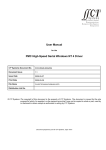
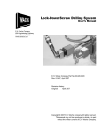
Only Port A is enabled and this mode is only supported on a HSS card
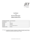
with a 100 MHz MPC862 processor. See Figure 1 and paragraph 3.3.12
for more details.
The following diagram indicates the criteria for selecting between normal and high speed mode :
Figure 1 : Normal / High Speed Mode Selection
CCII/HSS/6-MAN/002
CHSMAN02.WPD
2009-05-27
Issue 4.1
Page 5 of 52
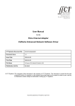
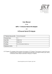
The following flow chart shows the functions involved in each mode :
Establish a connection to the HSS PMC card by calling
hssCreate_device() or
hssCreate_device_ex()
Configuring each port by calling
hssSet_port_config()
Normal Mode
Add call-back functions for
the receive and transmit
channel and for clock
detection if required.
Call function
hssAdd_callback()
Open Port by calling
hssOpen_port()
Polled Mode
Add call-back functions for
the transmit channel only
and for clock detection if
required.
Call function
hssAdd_callback()
User to implement own
polling function.
High Speed Mode
Add call-back functions for
the receive and transmit
channel and for clock
detection if required.
Call function
hssAdd_callback()
Open Port by calling
hssOpen_port()
Enable High Speed Mode by
calling
hssEnable_high_speed_port()
Enable Polled Mode by
calling
hssEnable_polled_mode()
Open Port by calling
hssOpen_port()
Send data by calling
hssSend_data()
Figure 2 : Overview of HSS Driver
CCII/HSS/6-MAN/002
CHSMAN02.WPD
2009-05-27
Issue 4.1
Page 6 of 52
3.3.2
Creating the Device
The HSS driver supports multiple HSS PMC on a single host. To establish a connection and construct all the
device specific structures, a user must create each of the devices separately, using the device ID to identify
it.
The device ID starts at 0 and increments by 1 for each of the devices. Device 0 refers to the device in the
lowest PMC slot. The HSS driver can not be used until the user has created the device.
Example : For device 0 :
/* Create all HSS devices */
hssCreate_device(0);
The device ID is used in all calls to the HSS driver to identify the correct device.
3.3.3
Configuring the Ports
The HSS PMC has four serial communications controllers (SCC's) [Ports A-D] that support UART and
HDLC/SDLC protocols, and two serial management controllers (SMC's) [Ports I&J] that support only
asynchronous UART.
After the HSS device has been created, the user must first set the default configuration for each of the ports.
To set the configuration of a port, a protocol-specific information structure is used. Examples of the required
structure is given in ccHssTest.c (for the UART protocol) and can be used as a starting point.
The structures allow the user to set all the protocol-specific options available on the HSS PMC communication
controller chip (the MPC860 PowerQUICC™). For available options for each of the structure fields, see [2.3.3].
Example : Set two SCC ports to UART mode and two to HDLC mode :
/* Set initial SCC port configuration */
hssSet_port_config(0, HSS_PORT_A, &uart_info);
hssSet_port_config(0, HSS_PORT_B, &uart_info);
hssSet_port_config(0, HSS_PORT_C, &hdlc_info);
hssSet_port_config(0, HSS_PORT_D, &hdlc_info);
/* Set initial SMC port configuration */
hssSet_port_config(0, HSS_PORT_I, &smc_uart_info);
hssSet_port_config(0, HSS_PORT_J, &smc_uart_info);
3.3.4
Adding Receive Buffers
Note : This step is not necessary anymore. Receive buffers are added automatically by the driver in the
hssOpen_port() function. It is still possible to call hssAdd_receive_buffer(), but this function will not do
anything.
CCII/HSS/6-MAN/002
CHSMAN02.WPD
2009-05-27
Issue 4.1
Page 7 of 52
3.3.5
Adding Call-back Functions
The HSS driver notifies the user of different events by calling a user defined Call-back function. The events for
which the user may specify one or more Call-back functions are :
Send Begin
Send Done
Receive Done
Clock Detect
- The driver has accepted the data for sending.
- The driver has finished sending the data.
- Data has been received and written into the user's buffer.
- A clock signal has been detected on that specific port.
Only one Call-back function for each event is recommended. For the user to receive data, at least the Receive
Done Call-back must be installed. While the Receive Done Call-back is executed, the corresponding buffer will
not be accessed by the HSS driver. The user can process the data in the Call-back function or copy the data
somewhere else for processing at the user's leisure.
Receive function prototype :
void Process_rx_data(int devid, int portid, int crc_error, int userid, int length, void *pdata);
Transmit Begin prototype :
void Process_tx_data(int devid, int portid, int dummy, int userid, int length, void *pdata);
Transmit Done prototype :
void Process_tx_data(int devid, int portid, int error, int userid, int length, void *pdata);
Clock Detection prototype :
void Process_clk_detect(int devid, int portid, int dummy1, int userid, int dummy2, void *dummy3);
devid
portid
crc_error
error
userid
length
pdata
dummy/1/2
dummy3
= device ID.
= port ID.
= HSS_OK (no CRC error).
= HSS_ERROR (CRC error).
= HSS_OK (send done OK).
= HSS_ERROR (buffer underrun or CTS lost : send not complete).
= user defined ID.
= length of received data.
= buffer with received data.
= variables not used (always 0).
= variable not used (always NULL).
Example : Add a Call-back function for handling receives :
/* Receive function prototype - this function is implemented by the user */
void Process_rx_data(int devid, int portid, int crc_error, int userid, int length, void *pdata);
/* Add receive Call-back */
hssAdd_callback(0, HSS_CB_ON_RECEIVE_DONE, Process_rx_data, 0);
CCII/HSS/6-MAN/002
CHSMAN02.WPD
2009-05-27
Issue 4.1
Page 8 of 52
3.3.6
Sending and Receiving Data
To send and receive data on a specified port, the user must first open the port. To stop sending or receiving
data from a port, the user must close the port.
Example : Send some data on device 0, port B :
/* Open port for sending data */
hssOpen_port(0, HSS_PORT_B, 50);
/* Send some data */
hssSend_data(0, HSS_PORT_B, 0, 256, pbuffer256, NO_WAIT);
/* Do other stuff */
/*
*/
/* Close port after final usage */
hssClose_port(0, HSS_PORT_B);
3.3.7
Destroying the Device
When the device is no longer required it should be destroyed to free system resources.
Example : Device 0 is no longer required :
/* Close ports after final usage */
hssClose_port(0, HSS_PORT_A);
hssClose_port(0, HSS_PORT_B);
hssClose_port(0, HSS_PORT_C);
hssClose_port(0, HSS_PORT_D);
hssClose_port(0, HSS_PORT_I);
hssClose_port(0, HSS_PORT_J);
/* Destroy device to free resources */
hssDestroy_device(0);
3.3.8
Detecting an active clock signal on ports
To detect when a port's clock signal becomes active, use the following function.
Example : Detecting a clock signal on device 0 and Port A :
/* Enable port to detect clock */
hssClock_detect(0, HSS_PORT_A);
A Call-back function gets called once a clock has been detected. After this Call-back function has been
serviced, the user can re-initialise the clock detection routine as shown above.
/* Clock detection prototype - this function is implemented by the user */
void Process_clk_event(int devid, int portid, int dummy1, int userid, int dummy2, void *dummy3);
/* adding clock_detect call-back */
hssAdd_callback (0, HSS_CB_ON_CLOCK_DETECT, Process_clk_detect, 0);
Note : The last 2 variables of the clock detection prototype function are dummy variables and are not
initialised.
CCII/HSS/6-MAN/002
CHSMAN02.WPD
2009-05-27
Issue 4.1
Page 9 of 52
3.3.9
Obtaining the current host and firmware version number
The following function prints out the current version number of the driver and firmware software :
/* Print current version number */
hssVersion_print(0);
Note : Run hssCreate_device(0) first.
The following function returns the firmware version stored in the EEPROM :
/* Return firmware version number : version*100 + revision*10 + beta */
hssFirmware_version(0, &version);
Note : This function may be called without running hssCreate_device(0) first.
3.3.10
HSS Built-In-Tests
The following function displays each port's statistics : e.g. how many bytes / packets have been accepted /
rejected / sent / received and how many errors were reported.
Example : Displaying each port's statistics for device 0 :
hssBit_report(0);
To clear the counters of the hssBit_report(0) function, use the function hssBit_clear(0).
Note : Instead of displaying each port’s statistics, the function hssBit_getstruct(..) only returns the
corresponding statistics in a structure. See paragraph 4.1.15.
3.3.11
Low Latency (Polled Mode) Setting
Note : This function is only available in HSS version 3.5.4.
The following function sets up a specific port to polled mode, and returns a pointer to 4 receive buffers :
Example : Enabling polled mode on device 0 and Port A :
hssEnable_polled_mode(0, HSS_PORT_A, pointer_to_buffer);
The format of the 4 receive buffers depends on the size of the RX and TX buffers (see paragraph 4.1.1), with
8 bytes appended at the end of each buffer. The structure of the 8 bytes is as follows :
Byte Number appended
at end of receive buffer
Description
Byte 1-4
Contains the length of the packet received.
Byte 5
Reserved.
Byte 6
Only used in HDLC : returns the HDLC receive error status :
HSS_OK - packet received OK.
HSS_HDLC_RX_CRC_ERROR - set when a frame contains a CRC error.
HSS_HDLC_RX_NONOCTET_ALIGNED_FRAME - set when a received frame contains a
number of bits not divisible by eight.
HSS_HDLC_RX_ABORT_SEQUENCE - set when at least seven consecutive ones are
received during frame reception.
Byte 7
Counter variable indicating the number of frames not serviced in time by the user. The data
will be lost (overwritten by the new data) in the process.
CCII/HSS/6-MAN/002
CHSMAN02.WPD
2009-05-27
Issue 4.1
Page 10 of 52
Byte 8
Receive Buffer Status Byte. One of :
HSS_RX_BUFFER_EMPTY - the buffer is empty.
HSS_RX_BUFFER_FULL - a packet has been received and data is valid.
HSS_RX_BUFFER_HANDLED - the user must set the receive buffer status byte to this flag,
indicating to the HSS card that this buffer has been handled.
The user should set up a task to search through the 4 receive buffers and poll byte 8. If the buffer is marked
as full, the length variable (byte 1-4) will be valid and data can be copied from the buffer. Once the buffer has
been handled, the user must set byte 8 accordingly.
Note : Before reading anything from the buffer, the user should invalidate the cache (vxWorks function
cacheInvalidate). After setting byte 8 to handled, the user should flush the cache (vxWorks function
cacheFlush). Only flush and invalidate the number of bytes needed, not the whole receive buffer.
3.3.12
High Speed Mode Setting for Port A
The following function sets up Port A to high speed mode and disables all other ports :
Example : Enabling high speed mode on device 0 and Port A :
hssEnable_high_speed_port(0);
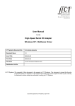
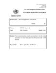
T1
T2
Packet Stream
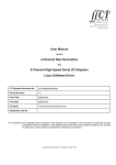
Figure 3 : Receive Packet Stream
This function should be used when the following criteria have to be met (with reference to Figure 1 and Figure
3) :
!
!
!
a receive baudrate of 5 Mbits/second or greater and
the time (T1) of 1 packet is less or equal to 100 μs and
the time (T2) between packets is less or equal to 10 μs.
The following table illustrates the number of bytes per packets that can be received in 100 μs for various
baudrates (values derived from the following equation : Bytes = [100 μs * Baudrate] / 8bits) :
Baudrate (in Mbits/second)
Number of bytes per packet (for T1 = 100 μs)
5
62.5
8
100
10
125
Note : This function is only supported on a HSS card with a 100MHz MPC862 processor.
CCII/HSS/6-MAN/002
CHSMAN02.WPD
2009-05-27
Issue 4.1
Page 11 of 52
3.3.13
HSS Power-On-Self-Tests
The Power-On-Self-Tests (POST) are available from HSS version 4.2 onwards. The tests are disabled by
default, but can be selectively enabled. The following tests are defined :
•
Magic number checking -
•
Flash CRC
-
•
EEPROM verification
-
•
RAM databus test
-
•
RAM addressbus test
-
•
RAM device test
-
checks the start of the flash for correct magic number. This test is always
performed and cannot be disabled.
checks that the checksum of the kernel in flash is correct. This test is
disabled by default.
verifies the contents of the EEPROM. If the contents is corrupt, the
EEPROM is reprogrammed. This test is always performed.
checks the databus connected to the RAM for any errors. This test is
disabled by default.
checks the addressbus connected to the RAM for any errors. This test
is disabled by default.
checks the whole RAM device for any errors. This test is disabled by
default.
If any of the above tests fail, an error code is flashed on the LEDs D3 and D4 and the card will not boot up
further. If the card is reset and the card still does not boot up, contact C²I² Systems (Pty) Ltd.
The error codes are continuously flashed on the LEDs D3 and D4, followed by a short break. The number of
flashes are defined as follows (see also header file hssPost.h) :
•
•
•
•
•
•
•
HSS_EEPROM_UPDATE
HSS_RAM_DATA_ERROR
HSS_RAM_ADDR_ERROR
HSS_RAM_DEVICE_ERROR
HSS_FLASH_MAGIC_ERROR
HSS_FLASH_KERNEL_CRC_ERROR
HSS_EEPROM_ERROR
-
1 flash
2 flashes
3 flashes
4 flashes
5 flashes
6 flashes
7 flashes
The above codes are also written to the EEPROM and may be read back with the following function :
Example : Obtain POST error status on device 0 :
hssPost_status(0, &data)
To enable / disable selected tests, the following function may be used :
Example : Enable all RAM tests but disable Flash CRC checking on device 0 :
hssPost_enable(0, HSS_POST_RAM_DATA_ENABLE | HSS_POST_RAM_ADDR_ENABLE |
HSS_POST_RAM_DEV_ENABLE);
Note : The function hssCreate_device() will return HSS_POWER_ON_SELFTEST_FAIL if any of the tests fail.
The function hssPost_status() may then be used to determine which one of the tests has failed.
CCII/HSS/6-MAN/002
CHSMAN02.WPD
2009-05-27
Issue 4.1
Page 12 of 52
4.
Application Program Interface (API)
4.1
High Speed Serial Driver Interface
The zip file ccHss4vx.y.z.h_files.zip contains the following header files :
crc.h - used for crc algorithm
hssDefs.h
hssHostDriver.h
hssControlIfc.h
hssPost.h - POST header included from HSS version 4.2
The following files should always be included :
hssDefs.h
hssHostDriver.h
hssControlIfc.h
CCII/HSS/6-MAN/002
CHSMAN02.WPD
2009-05-27
Issue 4.1
Page 13 of 52
4.1.1
Create Device
Function :
hssCreate_device
Purpose :
Create and initialise the HSS device specific structures.
Arguments :
<dev_id>
-
Device ID on the PCI bus. The HSS device in the lowest PCI slot : <dev_id> = 0,
next HSS device : <dev_id> = 1, etc.
Returns :
HSS_OK
HSS_INVALID_PARAM
HSS_PCI_INIT_FAIL
HSS_MEM_ALLOC_FAILED
-
HSS_DEVICE_NOT_FOUND
HSS_MEM_INVALID_ADDRESS
HSS_MEM_EEPROM_BUSY
-
HSS_POWER_ON_SELFTEST_FAIL
-
On success.
Invalid dev_id supplied.
PCI initialisation failed.
If HSS device structure could not be created in
memory.
If HSS device <dev_id> was not found on the PCI bus.
If the HSS device PCI address was not valid.
If HSS device could not read version number from
EEPROM.
If the POST failed.
hssStatus hssCreate_device(hssDeviceId dev_id);
Function :
hssCreate_device_ex
Purpose :
Create and initialize the HSS device specific structures. This extended version allows the
user to specify the maximum Rx & Tx buffer size for each port.
Arguments :
<dev_id>
-
<scc_#_size> <smc_#_size> <reserved1&2> -
Device ID on the PCI bus. The HSS device in the lowest PCI slot : <dev_id> = 0,
next HSS device : <dev_id> = 1, etc.
maximum Rx&Tx buffer size for specific scc port.
maximum Rx&Tx buffer size for specific smc port. (valid arguments : HSS_2K,
HSS_4K, HSS_8K, HSS_16K, HSS_32K)
2 reserved variables for future use.
Returns :
HSS_OK
HSS_INVALID_PARAM
HSS_PCI_INIT_FAIL
HSS_MEM_ALLOC_FAILED
-
HSS_DEVICE_NOT_FOUND
HSS_MEM_INVALID_ADDRESS
HSS_MEM_EEPROM_BUSY
-
HSS_POWER_ON_SELFTEST_FAIL
-
On success.
Invalid parameters supplied.
PCI initialisation failed.
If HSS device structure could not be created in
memory.
If HSS device <dev_id> was not found on the PCI bus.
If the HSS device PCI address was not valid.
if HSS device could not read version number from
EEPROM.
If the POST failed.
hssStatus hssCreate_device_ex(hssDeviceId dev_id, unsigned int scc_0_size, unsigned int scc_1_size,
unsigned int scc_2_size, unsigned int scc_3_size,
unsigned int smc_0_size, unsigned int smc_1_size,
unsigned int reserved1, unsigned int reserved2);
Note : One of these two functions has to be called (once per device) before any other function call to the
specified device will be valid. The function hssCreate_device() sets up the Rx & Tx buffer size for all
ports to the default value of 2Kbytes.
CCII/HSS/6-MAN/002
CHSMAN02.WPD
2009-05-27
Issue 4.1
Page 14 of 52
4.1.2
Destroy Device
Function :
hssDestroy_device
Purpose :
Destroy the HSS device specific structures.
Arguments :
<dev_id>
-
Returns :
HSS_OK
HSS_INVALID_PARAM
HSS_PCI_INIT_FAIL
HSS_ERROR
Device ID on the PCI bus. The HSS device in the lowest PCI slot : <dev_id> = 0,
next HSS device : <dev_id> = 1, etc.
-
On success.
Invalid dev_id supplied.
PCI initialisation failed
If the interrupt tasks have not been destroyed.
hssStatus hssDestroy_device(hssDeviceId dev_id);
Note : After this function is called, no other function call to the specified device will be valid, except for
hssCreate_device(..).
CCII/HSS/6-MAN/002
CHSMAN02.WPD
2009-05-27
Issue 4.1
Page 15 of 52
4.1.3
Port Exists?
Function :
hssPort_exists
Purpose :
Determine whether a port exists on the specified device.
Arguments :
<dev_id>
-
<port_id>
-
Device ID on the PCI bus. The HSS device in the lowest PCI slot : <dev_id> = 0,
next HSS device : <dev_id> = 1, etc.
Port to query.
-
If the port exists in hardware.
If the port does not exist in hardware.
Returns :
TRUE
FALSE
hssBool hssPort_exists(hssDeviceId dev_id, hssPortId port_id);
CCII/HSS/6-MAN/002
CHSMAN02.WPD
2009-05-27
Issue 4.1
Page 16 of 52
4.1.4
Set Port Configuration
Function :
hssSet_port_config
Purpose :
Set port protocol and protocol configuration.
Arguments :
<dev_id>
-
<port_id>
<p_info>
-
Device ID on the PCI bus. The HSS device in the lowest PCI slot : <dev_id> = 0,
next HSS device : <dev_id> = 1, etc.
Port to configure.
Pointer to information struct used for configuration.
Returns :
HSS_OK
HSS_PCI_INIT_FAIL
HSS_ERROR
HSS_INVALID_PARAM
HSS_PORT_NOT_INSTALLED
HSS_DEVICE_BUSY
HSS_DEVICE_NOT_RESPONDING
-
HSS_INCORRECT_PARAM_COMBINATION
-
On success.
PCI initialisation failed.
If the Tx/Rx tasks have not been destroyed.
Invalid dev_id or port_id supplied.
If the port does nor exists.
If no PCI buffer is available.
If the HSS control block could not be accessed
within a certain time.
If an incorrect parameter combination was
selected in the protocol structure.
hssStatus hssSet_port_config(hssDeviceId dev_id, hssPortId port_id, hssProtocolInfo* p_info);
Note : The <p_info> pointer must point to a valid hssProtocolInfo structure with all protocol information set as
required. If only a few items need to change, the hssGet_port_config(..) function should be used to fill
in the rest of the structure.
Warning : Do not call this function while sending or receiving data as this may result in data loss.
CCII/HSS/6-MAN/002
CHSMAN02.WPD
2009-05-27
Issue 4.1
Page 17 of 52
4.1.5
Get Port Configuration
Function :
hssGet_port_config
Purpose :
Get port protocol and protocol configuration.
Arguments :
<dev_id>
-
<port_id>
<p_info>
-
Device ID on the PCI bus. The HSS device in the lowest PCI slot : <dev_id> = 0,
next HSS device : <dev_id> = 1, etc.
Port to get configuration info from.
Pointer to information struct used for configuration.
Returns :
HSS_OK
HSS_ERROR
HSS_INVALID_PARAM
HSS_DEVICE_BUSY
HSS_DEVICE_NOT_RESPONDING
-
On success.
If the Tx/Rx tasks have not been destroyed.
Invalid dev_id or port_id supplied.
If no PCI buffer is available.
If the HSS control block could not be accessed within
a certain time.
hssStatus hssGet_port_config(hssDeviceId dev_id, hssPortId port_id, hssProtocolInfo* p_info);
Note : The <p_info> pointer must point to an existing hssProtocolInfo structure.
CCII/HSS/6-MAN/002
CHSMAN02.WPD
2009-05-27
Issue 4.1
Page 18 of 52
4.1.6
Open Port
Function :
hssOpen_port
Purpose :
Open specified port for send and receive.
Arguments :
<dev_id>
-
<port_id>
<priority>
Device ID on the PCI bus. The HSS device in the lowest PCI slot : <dev_id> = 0,
next HSS device : <dev_id> = 1, etc.
Port to open for send and receive.
-Priority of the send, receive and clock detection task servicing this port.
Returns :
HSS_OK
HSS_ERROR
HSS_INVALID_PARAM
HSS_PORT_NOT_INSTALLED
HSS_PORT_NOT_CONFIGURED
-
HSS_DEVICE_BUSY
HSS_DEVICE_NOT_RESPONDING
-
HSS_MEM_ALLOC_FAILED
-
On success.
If opening of port failed.
Invalid dev_id or port_id supplied
If the port does nor exists.
If an ‘Open' is attempted on a port before configuring
the port.
If no PCI buffer is available.
If the HSS control block could not be accessed within
a certain time.
If failed to create semaphore or spawn receive task.
hssStatus hssOpen_port(hssDeviceId dev_id, hssPortId port_id, hssINT32 priority);
Function :
hssOpen_port_fp
Purpose :
Open specified port for send and receive with floating point functionality.
Arguments :
<dev_id>
-
<port_id>
<priority>
<fp_options>
-
Device ID on the PCI bus. The HSS device in the lowest PCI slot : <dev_id> = 0,
next HSS device : <dev_id> = 1, etc.
Port to open for send and receive.
Priority of the send, receive and clock detection task servicing this port.
Floating point enable for send, receive and clock detect task
:HSS_TX_TASK_FP_ENABLE, HSS_RX_TASK_FP_ENABLE,
HSS_CLK_TASK_FP_ENABLE
Returns :
HSS_OK
HSS_ERROR
HSS_INVALID_PARAM
HSS_PORT_NOT_INSTALLED
HSS_PORT_NOT_CONFIGURED
-
HSS_DEVICE_BUSY
HSS_DEVICE_NOT_RESPONDING
-
HSS_MEM_ALLOC_FAILED
-
On success.
If opening of port failed.
Invalid dev_id or port_id supplied.
If the port does nor exists.
If an ‘Open' is attempted on a port before configuring
the port.
If no PCI buffer is available.
If the HSS control block could not be accessed within
a certain time.
If failed to create semaphore or spawn receive task.
hssStatus hssOpen_port_fp(hssDeviceId dev_id, hssPortId port_id, hssINT32 priority, char fp_options);
Note : These functions must be called prior to attempting to send or receive on any channel of the specified
port.
Opening a port spawns a receive, send and clock detect task for that specific port. The priority of these tasks
is specified by <priority>.
CCII/HSS/6-MAN/002
CHSMAN02.WPD
2009-05-27
Issue 4.1
Page 19 of 52
4.1.7
Close Port
Function :
hssClose_port
Purpose :
Close specified port for send and receive.
Arguments :
<dev_id>
-
<port_id>
-
Device ID on the PCI bus. The HSS device in the lowest PCI slot : <dev_id> = 0,
next HSS device : <dev_id> = 1, etc.
Port to close for send and receive.
Returns :
HSS_OK
HSS_ERROR
-
HSS_INVALID_PARAM
HSS_PORT_NOT_INSTALLED
HSS_PORT_NOT_CONFIGURED
-
HSS_DEVICE_BUSY
HSS_DEVICE_NOT_RESPONDING
-
On success.
If opening of port failed or Rx/Tx tasks have not been
destroyed..
Invalid dev_id or port_id supplied.
If the port does nor exists.
If an ‘Open' is attempted on a port before configuring
the port.
If no PCI buffer is available.
If the HSS control block could not be accessed within
a certain time.
hssStatus hssClose_port(hssDeviceId dev_id, hssPortId port_id);
Note : Closing a port a second time has no effect and still returns HSS_OK, since the port was successfully
closed.
CCII/HSS/6-MAN/002
CHSMAN02.WPD
2009-05-27
Issue 4.1
Page 20 of 52
4.1.8
Send Data
Function :
hssSend_data
Purpose :
Send data over the specified channel.
Arguments :
<dev_id>
-
<port_id>
<chan_id>
-
<nr_bytes>
<p_data>
<timeout>
-
Device ID on the PCI bus. The HSS device in the lowest PCI slot : <dev_id> = 0,
next HSS device : <dev_id> = 1, etc.
Port on which data must be sent.
Channel on which data must be sent. If a port has only one channel, <chan_id>
= 0.
Number of bytes to send.
Pointer to buffer with at least <nr_bytes> bytes of data.
Not used anymore.
Returns :
HSS_OK
HSS_INVALID_PARAM
HSS_PORT_NOT_INSTALLED
HSS_PORT_NOT_OPEN
HSS_DEVICE_BUSY
HSS_DEVICE_NOT_RESPONDING
-
On success.
Invalid dev_id or port_id supplied.
If the port does nor exists.
If the port is not open yet.
If no PCI buffer is available.
If the HSS control block could not be accessed within
a certain time.
hssStatus hssSend_data(hssDeviceId dev_id, hssPortId port_id, hssChannelId chan_id, hssCount nr_bytes,
hssBufferPtr p_data, hssInt32 timeout);
Note : The port must be opened before attempting to send data over it.
CCII/HSS/6-MAN/002
CHSMAN02.WPD
2009-05-27
Issue 4.1
Page 21 of 52
4.1.9
Add Receive Buffer
Function :
hssAdd_receive_buffer
Purpose :
Add a receive buffer to a specified channel.
Arguments :
<dev_id>
-
<port_id>
<chan_id>
-
<min_nr_bytes>
<max_nr_bytes>
<p_data>
-
Returns :
HSS_OK
-
Device ID on the PCI bus. The HSS device in the lowest PCI slot :
<dev_id> = 0, next HSS device : <dev_id> = 1, etc.
Port on which data must be received.
Channel on which data must be received. If a port has only one channel,
<chan_id> = 0.
Minimum number of bytes to receive before Call-back function is called.
Maximum number of bytes to receive into this buffer.
Pointer to buffer with space for at least <max_nr_bytes> bytes of data.
On success.
hssStatus hssAdd_receive_buffer(hssDeviceId dev_id, hssPortId port_id, hssChannelId chan_id, hssCount
min_nr_bytes, hssCount max_nr_bytes, hssBufferPtr p_data);
Note : This function is not used anymore. The receive buffers are added internally. The user may still call this
function, but this function returns only HSS_OK.
CCII/HSS/6-MAN/002
CHSMAN02.WPD
2009-05-27
Issue 4.1
Page 22 of 52
4.1.10
Remove Receive Buffer
Function :
hssRemove_receive_buffer
Purpose :
Remove a receive buffer from a specified channel.
Arguments :
<dev_id>
-
<port_id>
<chan_id>
-
<p_data>
-
Device ID on the PCI bus. The HSS device in the lowest PCI slot : <dev_id> = 0,
next HSS device : <dev_id> = 1, etc.
Port on which data must be received.
Channel on which data must be received. If a port has only one channel,
<chan_id> = 0.
Pointer to buffer to be removed.
Returns :
HSS_OK
-
On success.
hssStatus hssRemove_receive_buffer(hssDeviceId dev_id, hssPortId port_id, hssChannelId chan_id,
hssBufferPtr p_data);
Note : This function is not used anymore. The receive buffers are removed internally. The user may still call
this function, but this function returns only HSS_OK.
CCII/HSS/6-MAN/002
CHSMAN02.WPD
2009-05-27
Issue 4.1
Page 23 of 52
4.1.11
Add Call-back
Function :
hssAdd_callback
Purpose :
Add a user defined Call-back routine.
Arguments :
<dev_id>
-
<cb_type>
-
<Call-back>
<user_id>
-
Device ID on the PCI bus. The HSS device in the lowest PCI slot : <dev_id> = 0,
next HSS device : <dev_id> = 1, etc.
Call-back
type,
one
of
:
HSS_CB_ON_SEND_BEGIN,
HSS_CB_ON_SEND_DONE, HSS_CB_ON_RECEIVE_DONE,
HSS_CB_ON_CLOCK_DETECT
User function.
User identifier. This identifier will be passed to the Call-back function when it is
called.
Returns :
HSS_OK
HSS_INVALID_PARAM
HSS_MEM_ALLOC_FAILED
-
On success.
Invalid dev_id supplied.
If HSS Call-back node could not be created in memory
hssStatus hssAdd_callback(hssDeviceId dev_id, hssCallbackType cb_type, hssCallback Call-back, hssUserId
user_id);
Note : Four call-backs are provided for user notification from the driver :
HSS_CB_ON_SEND_BEGIN :
This Call-back will be called as soon as the data has been handed over to the driver for sending.
HSS_CB_ON_SEND_DONE :
This Call-back will be called when all the data for a given send has been sent by the driver.
HSS_CB_ON_RECEIVE_DONE :
This Call-back will be called when a block of data has been received by the driver. The user must add at
least one of these call-backs to receive data.
Only one call-back for each above type per device is recommended. The call-back function receives the port
id, such that the user can distinguish which port triggered the call-back. More than one call-back function may
be used, in which case the call-backs will be called in the sequence they were added.
HSS_CB_ON_CLOCK_DETECT :
This Call-back will be called when a clock signal has been detected on a port. The user must add only one
of these call-backs. This Call-back function will only be called once a port has been instructed to detect
a clock signal, e.g. calling the function hssClock_detect().
Note :
HSS_CB_ON_RECEIVE_BEGIN :
This Call-back does not exist anymore.
CCII/HSS/6-MAN/002
CHSMAN02.WPD
2009-05-27
Issue 4.1
Page 24 of 52
4.1.12
Remove Call-back
Function :
hssRemove_callback
Purpose :
Remove a user defined Call-back routine.
Arguments :
<dev_id>
-
<cb_type>
-
<Call-back>
<user_id>
-
Returns :
HSS_OK
HSS_INVALID_PARAM
Device ID on the PCI bus. The HSS device in the lowest PCI slot : <dev_id> = 0,
next HSS device : <dev_id> = 1, etc.
Call-back
type,
one
of
:
HSS_CB_ON_SEND_BEGIN,
HSS_CB_ON_SEND_DONE,HSS_CB_ON_RECEIVE_DONE,
HSS_CB_ON_CLOCK_DETECT
User function to remove.
User identifier. This identifier must be the same as the one passed to
hssAdd_callback.
-
On success.
Invalid dev_id supplied.
hssStatus hssRemove_callback(hssDeviceId dev_id, hssCallbackType cb_type, hssCallback Call-back,
hssUserId user_id);
CCII/HSS/6-MAN/002
CHSMAN02.WPD
2009-05-27
Issue 4.1
Page 25 of 52
4.1.13
Detecting an active clock signal on ports
Function :
hssClock_detect
Purpose :
Set up a port to detect when clock signal becomes active.
Arguments :
<dev_id>
-
<port_id>
-
Device ID on the PCI bus. The HSS device in the lowest PCI slot : <dev_id> = 0,
next HSS device : <dev_id> = 1, etc.
Port on which to detect clock signal.
Returns :
HSS_OK
HSS_INVALID_PARAM
HSS_PORT_NOT_INSTALLED
HSS_DEVICE_BUSY
HSS_DEVICE_NOT_RESPONDING
-
On success.
Invalid dev_id or port_id supplied.
If the port does nor exists.
If no PCI buffer is available.
If the HSS control block could not be accessed within
a certain time.
hssStatus hssClock_detect(hssDeviceId dev_id, hssPortId port_id);
CCII/HSS/6-MAN/002
CHSMAN02.WPD
2009-05-27
Issue 4.1
Page 26 of 52
4.1.14
Print out current version number
Function :
hssVersion_print
Purpose :
To obtain the current version number of the driver and firmware software. This function
essentially calls hssBit_getstruct(..) and prints out the contents of the hssBoardBitInfo
struct. See paragraph 4.1.15.
Arguments :
<dev_id>
-
Device ID on the PCI bus. The HSS device in the lowest PCI slot : <dev_id> = 0,
next HSS device : <dev_id> = 1, etc.
Returns :
HSS_OK
HSS_INVALID_PARAM
HSS_DEVICE_BUSY
HSS_DEVICE_NOT_RESPONDING
-
On success.
Invalid dev_id supplied.
If no PCI buffer is available.
If the HSS control block could not be accessed within
a certain time.
hssStatus hssVersion_print(hssDeviceId dev_id);
Note : Run first hssCreate_device(dev_id);
Function :
hssFirmware_version
Purpose :
Return the firmware version number stored in the EEPROM.
Arguments :
<dev_id>
-
<version>
-
Device ID on the PCI bus. The HSS device in the lowest PCI slot : <dev_id> = 0,
next HSS device : <dev_id> = 1, etc.
return value for version number : version*100 + revision*10 + beta.
Returns :
HSS_OK
HSS_INVALID_PARAM
HSS_DEVICE_NOT_FOUND
HSS_MEM_INVALID_ADDRESS
HSS_MEM_EEPROM_BUSY
-
On success.
Invalid dev_id supplied.
If HSS device <dev_id> was not found on the PCI bus.
If the HSS device PCI address was not valid.
If the HSS device could not read version number from
EEPROM.
hssStatus hssFirmware_version(hssDeviceId dev_id, hssUINT32 *version);
CCII/HSS/6-MAN/002
CHSMAN02.WPD
2009-05-27
Issue 4.1
Page 27 of 52
4.1.15
HSS Built-In-Test
The following structures define the HSS Built_In_Test variables (defined in hssControlIfc.h) :
BIT structures :
struct hssBoardBitInfoStruct
{
hssUINT32 board_number;
hssUINT32 board_type;
hssUINT32 firmware_version;
hssUINT32 firmware_revision;
hssUINT32 firmware_beta;
hssUINT32 oscillator_freq;
hssUINT32 hss_scc_mode[HSS_HW_NR_SCC];
hssUINT32 hss_smc_mode[HSS_HW_NR_SMC];
char firmware_creation_date[30];
};
typedef struct hssBoardBitInfoStruct hssBoardBitInfo;
struct hssSendBitInfoStruct
{
hssCount nr_accepted;
hssCount nr_rejected;
hssCount nr_errors;
hssCount nr_sent;
hssCount nr_bytes_accepted;
hssCount nr_bytes_rejected;
hssCount nr_bytes_sent;
};
typedef struct hssSendBitInfoStruct hssSendBitInfo;
struct hssReceiveBitInfoStruct
{
hssCount nr_buffers_busy;
hssCount nr_received;
hssCount nr_bytes_received;
hssCount nr_errors;
};
typedef struct hssReceiveBitInfoStruct hssReceiveBitInfo;
Main BIT structure :
struct hssBitInfoStruct
{
hssBoardBitInfo board_bit;
hssSendBitInfo tx_scc_bit[HSS_HW_NR_SCC];
hssReceiveBitInfo rx_scc_bit[HSS_HW_NR_SCC];
hssSendBitInfo tx_smc_bit[HSS_HW_NR_SMC];
hssReceiveBitInfo rx_smc_bit[HSS_HW_NR_SMC];
};
typedef struct hssBitInfoStruct hssBitInfo;
CCII/HSS/6-MAN/002
CHSMAN02.WPD
2009-05-27
Issue 4.1
Page 28 of 52
Three functions give access to the HSS Built_In_Test structures :
Function :
hssBit_getstruct
Purpose :
To obtain the latest BIT variables.
Arguments :
<dev_id>
-
<bit_info>
-
Device ID on the PCI bus. The HSS device in the lowest PCI slot : <dev_id> = 0,
next HSS device : <dev_id> = 1, etc.
Pointer to BIT info struct.
Returns :
HSS_OK
HSS_INVALID_PARAM
HSS_DEVICE_BUSY
HSS_DEVICE_NOT_RESPONDING
-
On success.
Invalid dev_id supplied.
If no PCI buffer is available.
If the HSS control block could not be accessed within
a certain time.
hssStatus hssBit_getstruct(hssDeviceId dev_id, hssBitInfo *bit_info);
Function :
hssBit_report
Purpose :
To display each port's statistics.
Arguments :
<dev_id>
-
Device ID on the PCI bus. The HSS device in the lowest PCI slot : <dev_id> = 0,
next HSS device : <dev_id> = 1, etc.
Returns :
HSS_OK
HSS_INVALID_PARAM
HSS_DEVICE_BUSY
HSS_DEVICE_NOT_RESPONDING
-
On success.
Invalid dev_id supplied.
If no PCI buffer is available.
If the HSS control block could not be accessed within
a certain time.
hssStatus hssBit_report(hssDeviceId dev_id);
Function :
hssBit_clear
Purpose :
To clear each port's counters.
Arguments :
<dev_id>
-
Device ID on the PCI bus. The HSS device in the lowest PCI slot : <dev_id> = 0,
next HSS device : <dev_id> = 1, etc.
Returns :
HSS_OK
HSS_INVALID_PARAM
HSS_DEVICE_BUSY
HSS_DEVICE_NOT_RESPONDING
-
On success.
Invalid dev_id supplied.
If no PCI buffer is available.
If the HSS control block could not be accessed within
a certain time.
hssStatus hssBit_clear(hssDeviceId dev_id);
CCII/HSS/6-MAN/002
CHSMAN02.WPD
2009-05-27
Issue 4.1
Page 29 of 52
4.1.16
Polled Mode Setting
Note : This function is only available in HSS version 3.5.4.
Function :
hssEnable_polled_mode
Purpose :
Setup a port to polled mode.
Arguments :
<dev_id>
-
<port_id>
<ptr_to_buffer> -
Device ID on the PCI bus. The HSS device in the lowest PCI slot : <dev_id> = 0,
next HSS device : <dev_id> = 1, etc.
Port to set to polled mode.
Pointer to 4 Rx buffers.
Returns :
HSS_OK
HSS_ERROR
HSS_INVALID_PARAM
HSS_DEVICE_NOT_RESPONDING
-
On success.
If the port is not open or if high speed mode has been
enabled already, this mode in not supported.
If <dev_id> is incorrect.
If the HSS control block could not be accessed within
HSS_CONFIG_TIMEOUT.
hssStatus hssEnable_polled_mode(hssDeviceId dev_id, hssPortId port_id, unsigned char *ptr_to_buffer[]);
Note : Call this function after opening the port. When the port is closed, the port reverts back to normal
(interrupt) mode.
CCII/HSS/6-MAN/002
CHSMAN02.WPD
2009-05-27
Issue 4.1
Page 30 of 52
4.1.17
High Speed Mode Setting
Function :
hssEnable_high_speed_port
Purpose :
Setup Port A on the HSS card to High Speed Mode. Only supported on a HSS card with
a 100MHz MPC862 processor.
Arguments :
<dev_id>
-
Device ID on the PCI bus. The HSS device in the lowest PCI slot : <dev_id> = 0,
next HSS device : <dev_id> = 1, etc.
Returns :
HSS_OK
HSS_ERROR
HSS_INVALID_PARAM
HSS_DEVICE_NOT_RESPONDING
-
On success.
The HSS card does not support High Speed Mode.
If <dev_id> is incorrect.
If the HSS control block could not be accessed within
HSS_CONFIG_TIMEOUT.
hssStatus hssEnable_high_speed_port(hssDeviceId dev_id);
Note : Call this function before opening the port. Once Port A has been setup to high speed mode, it is not
possible to revert back to normal mode. All other ports are disabled during high speed mode.
CCII/HSS/6-MAN/002
CHSMAN02.WPD
2009-05-27
Issue 4.1
Page 31 of 52
4.1.18
Enable / Disable POST
Function :
hssPost_enable
Purpose :
Enable / disable selected Power-On-Self-Tests.
Arguments :
<dev_id>
-
<test_enable>
-
Device ID on the PCI bus. The HSS device in the lowest PCI slot : <dev_id> = 0,
next HSS device : <dev_id> = 1, etc.
One or all of the following ORed together : HSS_POST_RAM_DATA_ENABLE,
HSS_POST_RAM_ADDR_ENABLE, HSS_POST_RAM_DEV_ENABLE,
HSS_POST_KERNEL_CRC_ENABLE.
Returns :
HSS_OK
HSS_INVALID_PARAM
HSS_DEVICE_NOT_FOUND
HSS_MEM_INVALID_ADDRESS
HSS_MEM_EEPROM_BUSY
-
On success.
Invalid dev_id supplied.
If HSS device <dev_id> was not found on the PCI bus.
If the HSS device PCI address was not valid.
If the HSS device could not read version number from
EEPROM.
hssStatus hssPost_enable(hssDeviceId dev_id, hssUINT8 test_enable);
Note : This function may be called without running hssCreate_device(0) first.
CCII/HSS/6-MAN/002
CHSMAN02.WPD
2009-05-27
Issue 4.1
Page 32 of 52
4.1.19
Return POST status
Function :
hssPost_status
Purpose :
Return Power-On-Self-Test status or error code.
Arguments :
<dev_id>
-
<status>
-
Device ID on the PCI bus. The HSS device in the lowest PCI slot : <dev_id> = 0,
next HSS device : <dev_id> = 1, etc.
Byte returning the error code of the POST. One of :
HSS_OK
On success.
HSS_EEPROM_UPDATE
EEPROM was corrupt and
was reprogrammed.
HSS_RAM_DATA_ERROR
RAM databus error.
HSS_RAM_ADDR_ERROR
RAM addressbus error.
HSS_RAM_DEVICE_ERROR
RAM device error.
HSS_FLASH_MAGIC_ERROR
Flash magic number corrupt.
HSS_FLASH_KERNEL_CRC_ERROR Flash CRC error.
HSS_EEPROM_ERROR
EEPROM read / write error.
Returns :
HSS_OK
HSS_INVALID_PARAM
HSS_DEVICE_NOT_FOUND
HSS_MEM_INVALID_ADDRESS
HSS_MEM_EEPROM_BUSY
-
On success.
Invalid dev_id supplied.
If HSS device <dev_id> was not found on the PCI bus.
If the HSS device PCI address was not valid.
If the HSS device could not read version number from
EEPROM.
hssStatus hssPost_status(hssDeviceId dev_id, hssUINT8 *status);
Note : This function may be called without running hssCreate_device(0) first.
CCII/HSS/6-MAN/002
CHSMAN02.WPD
2009-05-27
Issue 4.1
Page 33 of 52
4.2
Driver Data Structures
Each protocol defines a protocol information structure used to configure a port with protocol specific options.
This paragraph details the information structures used by each protocol and explains the use and limitations
of every structure member.
hssProtocolInfo structure :
struct hssProtocolInfoStruct
{
hssUINT32 protocol_id;
/* only used for HSS Front Panel boards - value ignored otherwise */
hssUINT32 elec_interface;
union
{
/* SCC info */
hssUartInfo uart;
hssHdlcInfo hdlc;
hssBisyncInfo bisync;
/* SMC info */
hssSmcUartInfo smc_uart;
} info;
};
typedef struct hssProtocolInfoStruct hssProtocolInfo;
protocol_id :
HSS_PROTOCOL_UART
HSS_PROTOCOL_HDLC
HSS_PROTOCOL_BISYNC
HSS_PROTOCOL_SMC_UART
elec_interface : (only used for HSS Front Panel boards)
HSS_RS485
HSS_RS232_INT_CTL_LINES
HSS_RS232_EXT_CTL_LINES
CCII/HSS/6-MAN/002
CHSMAN02.WPD
/* RS485/422 */
/* RS232 : control lines (RTS, CTS, CD) are connected
internally */
/* RS232 : control lines (RTS, CTS, CD) need to be connected
externally */
2009-05-27
Issue 4.1
Page 34 of 52
4.2.1
UART Mode
This protocol may only be used with the four SCC ports : Ports A-D.
4.2.1.1
UART Protocol Information Structure
The following structure is defined in the file hssControlIfc.h and is given here in abbreviated format (i.e.
reserved and obsolete members are not shown). Always use the structure as defined in hssControlIfc.h.
struct hssUartInfoStruct
{
hssUINT32 baud_rate;
hssUINT32 clock_source;
hssUINT32 flow_control;
hssUINT32 stop_bits;
hssUINT32 data_bits;
hssUINT32 uart_mode;
hssUINT32 freeze_tx;
hssUINT32 rx_zero_stop_bits;
hssUINT32 sync_mode;
hssUINT32 disable_rx_while_tx;
hssUINT32 parity_enable;
hssUINT32 rx_parity;
hssUINT32 tx_parity;
hssUINT32 diag_mode;
hssUINT32 max_receive_bytes;
hssUINT32 max_idl;
hssUINT32 brkcr;
hssUINT32 parec;
hssUINT32 frmec;
hssUINT32 nosec;
hssUINT32 brkec;
hssUINT32 uaddr1;
hssUINT32 uaddr2;
hssUINT32 toseq;
hssUINT32 cc[8];
hssUINT32 rccm;
};
typedef struct hssUartInfoStruct hssUartInfo;
CCII/HSS/6-MAN/002
CHSMAN02.WPD
2009-05-27
Issue 4.1
Page 35 of 52
4.2.1.2
UART Protocol Information Structure Members
Name
Options
Description
baud_rate
1200 - 115kbps (RS232)
1200 - 2.4Mbps (RS422/RS485)
0 - Indicates separate transmitter and receiver baudrates will be
set.
Any values permissible.
Units in bps.
This member is used to specify a
single baudrate for both
transmitter and receiver.
clock_source
HSS_CLOCK_DEFAULT
HSS_CLOCK_DEFAULT
connects BRG[1-4] to
Port[A-D].
For synchronous UART :
when transmit clock is set to
HSS_CLOCK_BRG[1-4], then
receive clock is still set to
HSS_CLOCK_EXT[1-4] for Port[AD].
For asynchronous UART :
transmit & receive clocks can be
set to one of
HSS_CLOCK_BRG[1-4] or
HSS_CLOCK_EXT[1-4].
HSS_CLOCK_BRG1
HSS_CLOCK_BRG2
HSS_CLOCK_BRG3
HSS_CLOCK_BRG4
Baudrate Generators [1-4].
HSS_CLOCK_EXT1
HSS_CLOCK_EXT2
HSS_CLOCK_EXT3
HSS_CLOCK_EXT4
External Clocks connected
on Pins : RXCLK[1-4]
(RS232) or CLKIN[1-4]
(RS485/RS422).
Note :
HSS_CLOCK_EXT[1-2]
can only be used for SCC
Port[A&B], while
HSS_CLOCK_EXT[3-4]
can only be used for SCC
Port[C&D].
flow_control
HSS_UART_FLOW_NORMAL
HSS_UART_FLOW_ASYNC
Normal or asynchronous flow
control.
stop_bits
HSS_UART_STOP_BITS_ONE
HSS_UART_STOP_BITS_TWO
Number of full stop bits.
data_bits
HSS_UART_DATA_BITS_5
HSS_UART_DATA_BITS_6
HSS_UART_DATA_BITS_7
HSS_UART_DATA_BITS_8
HSS_UART_DATA_BITS_9
HSS_UART_DATA_BITS_10
HSS_UART_DATA_BITS_11
HSS_UART_DATA_BITS_12
HSS_UART_DATA_BITS_13
HSS_UART_DATA_BITS_14
Number of data bits. Note only
ports I & J (i.e. the SMC ports) can
select 9 or more data bits.
uart_mode
HSS_UART_MODE_NORMAL
HSS_UART_MODE_MAN_MM
HSS_UART_MODE_AUTO_MM
Select UART mode : normal,
manual multidrop or automatic
multidrop mode.
freeze_tx
HSS_UART_FREEZE_TX_NORMAL
HSS_UART_FREEZE_TX_FREEZE
Pause (freeze) transmission.
Transmission continues when set
back to normal.
rx_zero_stop_bits
HSS_UART_RX_ZERO_STOP_BITS_NORMAL
HSS_UART_RX_ZERO_STOP_BITS_NONE
If set to none, the receiver
receives data without stop bits.
sync_mode
HSS_UART_SYNC_MODE_ASYNC
HSS_UART_SYNC_MODE_SYNC
Select asynchronous (normal) or
synchronous mode.
disable_rx_while_tx
HSS_UART_DISABLE_RX_WHILE_TX_NORMAL
HSS_UART_DISABLE_RX_WHILE_TX_DISABLE
Enable (normal) or disable
receiver while transmitting. Used
in multidrop mode to prevent
reception of own messages.
parity_enable
HSS_UART_PARITY_NO_PARITY
HSS_UART_PARITY_ENABLE
Enable or disable parity checking.
CCII/HSS/6-MAN/002
CHSMAN02.WPD
2009-05-27
Issue 4.1
Page 36 of 52
rx_parity, tx_parity
HSS_UART_PARITY_ODD
HSS_UART_PARITY_LOW
HSS_UART_PARITY_EVEN
HSS_UART_PARITY_HIGH
diag_mode
HSS_DIAG_NORMAL
Receive and transmit parity.
Parity will only be checked if parity
is enabled.
Normal operation. Use this
for external loopback.
HSS_DIAG_LOOPBACK
Internal loopback : TXD
& RXD are connected
internally. The value on
RXD, CTS & CD is
ignored. The transmitter
and receiver share the
same clock source.
HSS_DIAG_ECHO
The transmitter
automatically resends
received data bit-by-bit.
HSS_DIAG_LOOPBACK_ECHO
Loopback and echo
operation occur
simultaneously.
Set diagnostic mode.
External loopback - RS485 :
connect TXD+ to RXD+, TXD- to
RXD-, (TXCLK+ to RXCLK+ and
TXCLK- to RXCLK- for
synchronous mode).
External loopback - RS232 :
connect TXD to RXD, (TXCLK to
RXCLK for synchronous mode)
and RTS to CTS & CD.
For HSS Front Panel I/O Board :
program elec_interface=
HSS_RS232_INT_CTL_LINES
and connect TXD to RXD, (TXCLK
to RXCLK for synchronous mode).
Ignore RTS, CTL & CD.
max_receive_bytes
1 to 2048 (default) or up to 32 Kbytes, depending on how many
bytes have been allocated to the Rx & Tx buffers (See function
hssCreate_device_ex()).
Maximum number of bytes that
may be copied into a buffer.
max_idl
0 to 2048 (default) or up to 32 Kbytes, depending on how many
bytes have been allocated to the Rx & Tx buffers (See function
hssCreate_device_ex()).
Maximum idle characters. When a
character is received, the receiver
begins counting idle characters. If
max_idl idle characters are
received before the next data
character, an idle timeout occurs
and the buffer is closed. Thus,
max_idl offers a way to demarcate
frames. To disable the feature,
clear max_idl. The bit length of an
idle character is calculated as
follows : 1 + data length (5-9) + 1
(if parity is used) + number of stop
bits (1-2). For 8 data bits, no
parity, and 1 stop bit, the character
length is 10 bits.
brkcr
0 - 2048
Number of break characters sent
by transmitter. For 8 data bits, no
parity, 1 stop bit, and 1 start bit,
each break character consists of
10 zero bits.
parec
0 - 65535
Number of received parity errors.
frmec
0 - 65535
Number of received characters
with framing errors.
nosec
0 - 65535
Number of received characters
with noise errors.
brkec
0 - 65535
Number of break conditions on the
signal.
uaddr1, uaddr2
0x0000 - 0x00FF
Address in multidrop mode. Only
the lower 8 bits are used so the
upper 8 bits should be cleared.
toseq
0x0000 - 0x00FF
Transmit out of sequence
character (e.g. XON, XOFF).
CCII/HSS/6-MAN/002
CHSMAN02.WPD
2009-05-27
Issue 4.1
Page 37 of 52
cc[8]
0b00------cccccccc 0b10------cccccccc -
valid entry
entry not valid and is not used.
Control character 1 to 8. These
characters can be used to delimit
received messages.
------ (6 bits) - reserved. Initialise to
zero.
cccccccc (8 bits) - defines control
characters to be compared to the
incoming character.
rccm
0b11------00000000 0b11------11111111 -
CCII/HSS/6-MAN/002
CHSMAN02.WPD
ignore these bits when
comparing incoming character
enable comparing the incoming
character to cc[n].
2009-05-27
Receive control character mask. A
one enables comparison and a
zero masks it.
Issue 4.1
Page 38 of 52
4.2.2
HDLC Mode
This protocol may only be used with the four SCC ports : Ports A-D.
4.2.2.1 HDLC Protocol Information Structure
The following structure is defined in the file hssControlIfc.h and is given here in abbreviated format (i.e. reserved
and obsolete members are not shown). Always use the structure as defined in hssControlIfc.h.
struct hssHdlcInfoStruct
{
hssUINT32 tx_baud_rate;
hssUINT32 rx_baud_rate;
hssUINT32 clock_source;
hssUINT32 crc_mode;
hssUINT32 diag_mode;
hssUINT32 max_receive_bytes;
hssUINT32 max_frame_bytes;
hssUINT32 address_mask;
hssUINT32 address1;
hssUINT32 address2;
hssUINT32 address3;
hssUINT32 address4;
hssUINT32 nr_flags_between_frames;
hssUINT32 retransmit_enabled;
hssUINT32 flag_sharing_enabled;
hssUINT32 rx_disabled_during_tx;
hssUINT32 bus_mode;
hssUINT32 bus_mode_rts;
hssUINT32 multiple_tx_frames;
hssUINT32 encoding_method;
hssUINT32 preamble_length;
hssUINT32 preamble_pattern;
hssUINT32 send_idles_or_flags;
};
typedef struct hssHdlcInfoStruct hssHdlcInfo;
CCII/HSS/6-MAN/002
CHSMAN02.WPD
2009-05-27
Issue 4.1
Page 39 of 52
4.2.2.2 HDLC Protocol Information Structure Members
Name
tx_baud_rate,
rx_baud_rate
Options
1200 - 115kbps (RS232)
1200 - 12Mbps (RS422/RS485)
Any values permissible.
Units in bps.
NB : It is not possible to specify
the transmitter and receiver
baudrate separately anymore.
Set both variables to the same
baudrate.
OBSOLETE VARIABLES
tx_clock_direction
rx_clock_direction
clock_source
Description
HSS_CLOCK_DEFAULT
HSS_CLOCK_BRG1
HSS_CLOCK_BRG2
HSS_CLOCK_BRG3
HSS_CLOCK_BRG4
Baudrate Generators [1-4].
HSS_CLOCK_EXT1
HSS_CLOCK_EXT2
HSS_CLOCK_EXT3
HSS_CLOCK_EXT4
External Clocks connected
on Pins : RXCLK[1-4]
(RS232) or CLKIN[1-4]
(RS485/RS422).
HSS_CLOCK_DEFAULT
connects BRG[1-4] to Port[A-D].
For NRZ/NRZI : when transmit
clock is set to
HSS_CLOCK_BRG[1-4], then
receive clock is still set to
HSS_CLOCK_EXT[1-4] for
Port[A-D].
For FM0/1, Manchester & Diff.
Manchester : transmit & receive
clocks can be set to one of
HSS_CLOCK_BRG[1-4] or
HSS_CLOCK_EXT[1-4].
Note :
HSS_CLOCK_EXT[1-2]
can only be used for SCC
Port[A&B], while
HSS_CLOCK_EXT[3-4]
can only be used for SCC
Port[C&D].
crc_mode
HSS_HDLC_CRC_MODE_16_BIT
HSS_HDLC_CRC_MODE_32_BIT
diag_mode
HSS_DIAG_NORMAL
HSS_DIAG_LOOPBACK
max_receive_bytes
CCII/HSS/6-MAN/002
CHSMAN02.WPD
HDLC CRC mode.
Normal operation. Use this
for external loopback.
Internal loopback : TXD
& RXD are connected
internally. The value on
RXD, CTS & CD is
ignored. The transmitter
and receiver share the
same clock source.
HSS_DIAG_ECHO
The transmitter
automatically resends
received data bit-by-bit.
HSS_DIAG_LOOPBACK_ECHO
Loopback and echo
operation occur
simultaneously.
1 to (2048 - CRC bytes (2 or 4)) (default) or up to (32 Kbytes CRC bytes (2 or 4)), depending on how many bytes have been
allocated to the Rx & Tx buffers (See function
hssCreate_device_ex()).
2009-05-27
Set diagnostic mode.
External loopback - RS485 :
connect TXD+ to RXD+, TXD- to
RXD-, (TXCLK+ to RXCLK+ and
TXCLK- to RXCLK- for
synchronous mode).
External loopback - RS232 :
connect TXD to RXD, (TXCLK to
RXCLK for synchronous mode)
and RTS to CTS & CD.
For HSS Front Panel I/O Board :
program elec_interface=
HSS_RS232_INT_CTL_LINES
and connect TXD to RXD,
(TXCLK to RXCLK for
synchronous mode). Ignore RTS,
CTL & CD.
For synchronous mode :
see encoding_method.
Maximum number of bytes to
receive before closing buffer. Set
equal to max_frame_bytes.
Issue 4.1
Page 40 of 52
max_frame_bytes
1 to 2048 (default) or up to 32 Kbytes, depending on how many
bytes have been allocated to the Rx & Tx buffers (See function
hssCreate_device_ex()).
Maximum number of bytes per
frame. Set equal to the number
of data bytes plus the number of
CRC bytes (either 2 or 4) per
frame.
address_mask
0x0000 - 0xFFFF
HDLC address mask. A one
enables comparison and a zero
masks it.
address1, address2,
address3, address4
0x0000 - 0xFFFF
Four address registers for
address recognition. The SCC
reads the frame address from the
HDLC receiver, compares it
with the address registers, and
masks the result with
address_mask.
For example, to recognize a
frame that begins 0x7E (flag),
0x68, 0xAA,
using 16-bit address recognition,
the address registers should
contain 0xAA68 and
address_mask
should contain 0xFFFF. For 8-bit
addresses, clear the eight highorder address bits.
nr_flags_between_frames
0 - 15
Minimum number of flags
between or before frames.
retransmit_enabled
TRUE
FALSE
Enable re-transmit.
flag_sharing_enabled
TRUE
FALSE
Enable flag sharing.
rx_disabled_during_tx
TRUE
FALSE
Disable receive during transmit.
bus_mode
TRUE
FALSE
Enable bus mode.
bus_mode_rts
TRUE
FALSE
Enable special RTS operation in
HDLC bus mode.
multiple_tx_frames
TRUE
FALSE
Enable multiple frames in
transmit FIFO.
encoding_method
HSS_HDLC_ENCODING_METHOD_NRZ
HSS_HDLC_ENCODING_METHOD_NRZI_MARK
HSS_HDLC_ENCODING_METHOD_NRZI_SPACE
HSS_HDLC_ENCODING_METHOD_FM0
HSS_HDLC_ENCODING_METHOD_FM1
HSS_HDLC_ENCODING_METHOD_MANCHESTER
HSS_HDLC_ENCODING_METHOD_DIFF_MANCHESTER
Rx / Tx encoding method. NRZ
and NRZI use no DPLL. FM0/1,
Manchester & Diff_Manchester
use the DPLL for clock
recovery.The clock rate is 16x
when the DPLL is used.
preamble_length
HSS_DPLL_PREAMBLE_LENGTH_0
HSS_DPLL_PREAMBLE_LENGTH_8
HSS_DPLL_PREAMBLE_LENGTH_16
HSS_DPLL_PREAMBLE_LENGTH_32
HSS_DPLL_PREAMBLE_LENGTH_48
HSS_DPLL_PREAMBLE_LENGTH_64
HSS_DPLL_PREAMBLE_LENGTH_128
Determines the length of the
preamble pattern.
preamble_pattern
HSS_DPLL_PREAMBLE_PATTERN_00
HSS_DPLL_PREAMBLE_PATTERN_10
HSS_DPLL_PREAMBLE_PATTERN_01
HSS_DPLL_PREAMBLE_PATTERN_11
Determines what bit pattern
precedes each Tx frame.
CCII/HSS/6-MAN/002
CHSMAN02.WPD
2009-05-27
Issue 4.1
Page 41 of 52
send_idles_or_flags
HSS_HDLC_SEND_IDLES
HSS_HDLC_SEND_FLAGS_SYNCS
Send either idles or flags/syncs
between frames as defined by
the protocol. For HDLC the flag
is defined as 0x7E. NRZI
encoding methods may only be
used with flags/syncs.
4.2.2.3 Preamble Requirements
Decoding Method
Preamble Pattern
Minimum Preamble Length
Required
NRZI Mark
All zeros
8-bit
NRZI Space
All ones
8-bit
FM0
All ones
8-bit
FM1
All zeros
8-bit
101010...10
8-bit
All ones
8-bit
Manchester
Differential Manchester
CCII/HSS/6-MAN/002
CHSMAN02.WPD
2009-05-27
Issue 4.1
Page 42 of 52
4.2.3
BISYNC Mode
This protocol may only be used with the four SCC ports : Ports A-D.
4.2.3.1 BISYNC Protocol Information Structure
The following structure is defined in the file hssControlIfc.h and is given here in abbreviated format (i.e. reserved
and obsolete members are not shown). Always use the structure as defined in hssControlIfc.h.
struct hssBisyncInfoStruct
{
hssUINT32 baud_rate;
hssUINT32 clock_source;
hssUINT32 max_receive_bytes;
hssUINT32 min_no_sync_pairs;
hssUINT32 crc_select;
hssUINT32 receive_bcs;
hssUINT32 rx_transparant_mode;
hssUINT32 reverse_data;
hssUINT32 disable_rx_while_tx;
hssUINT32 rx_parity;
hssUINT32 tx_parity;
hssUINT32 diag_mode;
hssUINT32 crcc;
hssUINT32 prcrc;
hssUINT32 ptcrc;
hssUINT32 parec;
hssUINT32 bsync;
hssUINT32 bdle;
hssUINT32 cc[8];
hssUINT32 rccm;
hssUINT32 sync;
hssUINT32 syn_length;
hssUINT32 send_idles_or_flags;
};
typedef struct hssBisyncInfoStruct hssBisyncInfo;
CCII/HSS/6-MAN/002
CHSMAN02.WPD
2009-05-27
Issue 4.1
Page 43 of 52
4.2.3.2 BISYNC Protocol Information Structure Members
Name
Options
Description
baud_rate
1200 - 115kbps (RS232)
1200 - 12Mbps (RS422/RS485)
Any values permissible.
Units in bps.
This member is used to specify a
single baudrate for both transmitter
and receiver.
clock_source
HSS_CLOCK_DEFAULT
HSS_CLOCK_DEFAULT connects
BRG[1-4] to Port[A-D].
HSS_CLOCK_BRG1
HSS_CLOCK_BRG2
HSS_CLOCK_BRG3
HSS_CLOCK_BRG4
Baudrate Generators [1-4].
HSS_CLOCK_EXT1
HSS_CLOCK_EXT2
HSS_CLOCK_EXT3
HSS_CLOCK_EXT4
External Clocks connected
on Pins : RXCLK[1-4]
(RS232) or CLKIN[1-4]
(RS485/RS422).
When the transmit clock is set to
HSS_CLOCK_BRG[1-4], then
receive clock is still set to
HSS_CLOCK_EXT[1-4] for Port[A-D].
Note :
HSS_CLOCK_EXT[1-2]
can only be used for SCC
Port[A&B], while
HSS_CLOCK_EXT[3-4]
can only be used for SCC
Port[C&D].
max_receive_bytes
1 to (2048 - 2 CRC bytes) (default) or up to (32 Kbytes - 2 CRC
bytes), depending on how many bytes have been allocated to the
Rx & Tx buffers (See function hssCreate_device_ex()).
Maximum number of bytes to receive
before closing buffer.
min_no_sync_pairs
0b0000 (0 pairs) - 0b1111 (16 pairs)
Minimum number of SYN1-SYN2
pairs sent between or before
messages. The entire pair is always
sent, regardless of the syn_length
variable.
crc_select
HSS_BISYNC_CRC_MODE_16
HSS_BISYNC_CRC_MODE_LRC
CRC selection.
1 : CRC16 (X16 + X15 + X2 + 1) :
initialise prcrc & ptcrc to all zeros or
all ones.
2 : LRC (sum check) : for even LRC,
initialise prcrc & ptcrc to zeros, for
odd LRC initialise to ones.
receive_bcs
TRUE
FALSE
Enable Receive Block Check
Sequence (BCS).
rx_transparant_mode
TRUE
FALSE
Enable Receiver transparent mode.
FALSE : normal receiver mode with
SYNC stripping and control character
recognition.
TRUE : transparent receiver mode.
SYNC’s, DLE’s and control
characters are recognised only after
the leading DLE character. The
receiver calculates the CRC16
sequence even if it is programmed to
LRC while in transparent mode.
Initialize prcrc to the CRC16 preset
value before setting
rx_transparant_mode.
reverse_data
CCII/HSS/6-MAN/002
CHSMAN02.WPD
TRUE
FALSE
Enable Reverse data.
2009-05-27
Issue 4.1
Page 44 of 52
disable_rx_while_tx
TRUE
FALSE
Disable receiver while sending.
rx_parity
tx_parity
HSS_BISYNC_PARITY_ODD
HSS_BISYNC_PARITY_LOW
HSS_BISYNC_PARITY_EVEN
HSS_BISYNC_PARITY_HIGH
Receive and transmit parity. Parity is
ignored unless crc_select = LRC.
diag_mode
HSS_DIAG_NORMAL
Normal operation. Use this
for external loopback.
HSS_DIAG_LOOPBACK
Internal loopback : TXD &
RXD are connected
internally. The value on
RXD, CTS & CD is ignored.
The transmitter and
receiver share the same
clock source.
HSS_DIAG_ECHO
The transmitter
automatically resends
received data bit-by-bit.
HSS_DIAG_LOOPBACK_ECHO
Loopback and echo
operation occur
simultaneously.
Set diagnostic mode.
External loopback - RS485 :
connect TXD+ to RXD+, TXD- to
RXD-, TXCLK+ to RXCLK+ and
TXCLK- to RXCLK-.
External loopback - RS232 :
connect TXD to RXD, TXCLK to
RXCLK and RTS to CTS & CD.
For HSS Front Panel I/O Board :
program elec_interface=
HSS_RS232_INT_CTL_LINES and
connect TXD to RXD, TXCLK to
RXCLK. Ignore RTS, CTL & CD.
crcc
0
CRC constant value.
prcrc
ptcrc
0x0000 or
0xFFFF
Preset receiver / transmitter
CRC16/LRC. These values should be
preset to all
ones or zeros, depending on the BCS
used.
parec
0 - 65535
Number of received parity errors.
bsync
0bv0000000ssssssss
BISYNC SYNC register. Contains the
value of the SYNC character stripped
from incoming
data on receive once the receiver
synchronizes to the data using the
SYN1- SYN2 pair.
v - if v = 1and the receiver is not in
hunt mode when a SYNC character
is received, this character is
discarded.
ssssssss (8 bits) - SYNC character.
When using 7-bit characters with
parity, the parity bit should be
included in the SYNC register value.
bdle
0bv0000000dddddddd
BISYNC DLE register. In transparent
mode, the receiver discards any DLE
character received.
v - if v = 1and the receiver is not in
hunt mode when a DLE character is
received, this character is discarded.
dddddddd (8 bits) - DLE character.
This character tells the receiver that
the next character is text.
CCII/HSS/6-MAN/002
CHSMAN02.WPD
2009-05-27
Issue 4.1
Page 45 of 52
cc[8]
0b0bh-----cccccccc 0b1bh-----cccccccc -
valid entry
entry not valid and is not used.
Control character 1 to 8.
----- (5 bits) - reserved. Initialise to
zero.
b - Bloch check sequence expected.
A maskable interrupt is generated
after the buffer is closed.
b = 0 : the character is written into
the receive buffer and the buffer is
closed.
b = 1 : the character is written into
the receive buffer. The receiver waits
for 1 LRC or 2 CRC bytes and then
closes the buffer.
h - Enables hunt mode when the
current buffer is closed.
h = 0 : the BISYNC controller
maintains character synchronisation
after closing the buffer.
h = 1 : the BISYNC controller enters
hunt mode after closing the buffer.
When b = 1, the controller enters
hunt mode after receiving LRC or
CRC.
cccccccc (8 bits) - defines control
characters to be compared to the
incoming character. When using 7-bit
characters with parity, include the
parity bit in the character value.
rccm
0b11------00000000 0b11------11111111 -
ignore these bits when comparing
incoming character
enable comparing the incoming character
to cc[n].
Receive control character mask. A
one enables comparison and a zero
masks it.
sync
0xssss (2 bytes)
SYNC character : should be
programmed with the sync pattern.
syn_length
HSS_BISYNC_SYNL_8
HSS_BISYNC_SYNL_16
HSS_BISYNC_SYNL_8 : should be
chosen to implement
mono-sync protocol. The
receiver synchronizes on an 8-bit
sync pattern in sync.
HSS_BISYNC_SYNL_16 : The
receiver synchronizes on a 16-bit
sync pattern stored in sync.
send_idles_or_flags
CCII/HSS/6-MAN/002
CHSMAN02.WPD
HSS_BISYNC_SEND_IDLES
HSS_BISYNC_SEND_FLAGS_SYNCS
2009-05-27
Send either idles or flags/syncs
between frames as defined by the
protocol.The flag character is equal
to sync.
Issue 4.1
Page 46 of 52
4.2.4
SMC UART Mode
This protocol may only be used with the two SMC ports : Ports I&J.
4.2.4.1 SMC UART Protocol Information Structure
The following structure is defined in the file hssControlIfc.h and is given here in abbreviated format (i.e. reserved
and obsolete members are not shown). Always use the structure as defined in hssControlIfc.h.
struct hssSmcUartInfoStruct
{
hssUINT32 baud_rate;
hssUINT32 clock_source;
hssUINT32 stop_bits;
hssUINT32 data_bits;
hssUINT32 parity_enable;
hssUINT32 parity_mode;
hssUINT32 diag_mode;
hssUINT32 max_receive_bytes;
hssUINT32 max_idl;
};
typedef struct hssSmcUartInfoStruct hssSmcUartInfo;
CCII/HSS/6-MAN/002
CHSMAN02.WPD
2009-05-27
Issue 4.1
Page 47 of 52
4.2.4.2 SMC UART Protocol Information Structure Members
Name
Options
Description
baud_rate
1200 - 115.2kbps (RS232/RS422/RS485)
Any values permissible.
Units in bps.
This member is used to
specify a single baudrate for
both transmitter and
receiver.
clock_source
HSS_CLOCK_DEFAULT
HSS_CLOCK_DEFAULT
connects BRG[1-2] to
Port[I-J].
Transmit & receive clocks
can be set to one of
HSS_CLOCK_BRG[1-4] or
HSS_CLOCK_EXT[1-4].
HSS_CLOCK_BRG1
HSS_CLOCK_BRG2
HSS_CLOCK_BRG3
HSS_CLOCK_BRG4
Baudrate Generators [1-4].
HSS_CLOCK_EXT1
HSS_CLOCK_EXT2
HSS_CLOCK_EXT3
HSS_CLOCK_EXT4
External Clocks connected on
Pins : RXCLK[1-4] (RS232) or
CLKIN[1-4] (RS485/RS422).
Note : HSS_CLOCK_EXT[1-2]
can only be used for SMC Port I,
while HSS_CLOCK_EXT[3-4]
can only be used for SMC Port J.
stop_bits
HSS_UART_STOP_BITS_ONE
HSS_UART_STOP_BITS_TWO
Number of full stop bits.
data_bits
HSS_UART_DATA_BITS_5
HSS_UART_DATA_BITS_6
HSS_UART_DATA_BITS_7
HSS_UART_DATA_BITS_8
HSS_UART_DATA_BITS_9
HSS_UART_DATA_BITS_10
HSS_UART_DATA_BITS_11
HSS_UART_DATA_BITS_12
HSS_UART_DATA_BITS_13
HSS_UART_DATA_BITS_14
Number of data bits. Note
only ports I & J (i.e. the
SMC ports) can select 9 or
more data bits.
parity_enable
HSS_UART_PARITY_NO_PARITY
HSS_UART_PARITY_ENABLE
Enable or disable parity
checking.
parity_mode
HSS_UART_SMC_PARITY_ODD
HSS_UART_SMC_PARITY_EVEN
Receive and transmit parity.
Parity will only be checked if
parity is enabled.
diag_mode
HSS_DIAG_NORMAL
Normal operation. Use this for
external loopback.
HSS_DIAG_LOOPBACK
max_receive_bytes
CCII/HSS/6-MAN/002
CHSMAN02.WPD
Internal loopback : TXD & RXD
are connected internally. The
value on RXD is ignored.
HSS_DIAG_ECHO
The transmitter automatically
resends received data bit-by-bit.
HSS_DIAG_LOOPBACK_ECHO
Loopback and echo operation
occur simultaneously.
1 to 2048 (default) or up to 32 Kbytes, depending on how many bytes
have been allocated to the Rx & Tx buffers (See function
hssCreate_device_ex()).
2009-05-27
Set diagnostic mode.
External loopback - RS485
: connect TXD+ to RXD+ &
TXD- to RXD-.
External loopback - RS232
: connect TXD to RXD.
Maximum number of bytes
that may be copied into a
buffer.
Issue 4.1
Page 48 of 52
max_idl
CCII/HSS/6-MAN/002
CHSMAN02.WPD
0 to 2048 (default) or up to 32 Kbytes, depending on how many bytes
have been allocated to the Rx & Tx buffers (See function
hssCreate_device_ex()).
2009-05-27
Maximum idle characters.
When a character is
received, the receiver
begins counting idle
characters. If max_idl idle
characters are received
before the next data
character, an idle timeout
occurs and the buffer is
closed. Thus, max_idl offers
a way to demarcate frames.
To disable the feature, clear
max_idl. The bit length of an
idle character is calculated
as follows : 1 + data length
(5-14) + 1 (if parity is used)
+ number of stop bits (1-2).
For 8 data bits, no parity,
and 1 stop bit, the character
length is 10 bits.
Issue 4.1
Page 49 of 52
5.
Getting Started
After installing the host driver according to paragraph 3.1, test the host driver following the test procedure given
in hssTest.txt.
CCII/HSS/6-MAN/002
CHSMAN02.WPD
2009-05-27
Issue 4.1
Page 50 of 52
6.
Contact Details
6.1
Contact Person
Direct all correspondence and / or support queries to the Project Manager (HSS) at C²I² Systems.
6.2
Physical Address
C²I² Systems (Pty) Ltd
Unit 3, 67 Rosmead Avenue
Kenilworth
Cape Town
7701
South Africa
6.3
Postal Address
C²I² Systems (Pty) Ltd
P.O. Box 171
Rondebosch
Cape Town
7701
South Africa
6.4
Voice and Electronic Contacts
Tel :
Fax :
Email :
Email :
URL :
6.5
+27) 21 683 5490
(+27) 21 683 5435
[email protected]
[email protected]
http://www.ccii.co.za/
Product Support
Support on C²I² Systems' products is available telephonically between Monday and Friday from 09:00 to 17:00
CAT. Central African Time (CAT = GMT + 2).
Email support is available at [email protected]
CCII/HSS/6-MAN/002
CHSMAN02.WPD
2009-05-27
Issue 4.1
Page 51 of 52
Annexure A
Making Changes to sysLib.c for X86
The PCI free memory space needs to be defined in the memory descriptor table. Consult the relevant reference
manual and obtain the upper address of the PCI memory. Allocate at least 5 megabytes of memory per HSS card.
Subtract that amount from the upper address of the PCI memory, and use this value as the base of the PCI
memory space.
Note : if there are other devices on the PCI bus, it may be necessary to allocate more memory.
Example : For 2 HSS cards, allocate 10 megabytes of memory. If the upper address of the PCI memory space is
defined as 0xFFF00000, then subtracting 10 megabytes gives a base address of : 0xFFF00000 - 0xA00000 =
0xFF500000.
In the PC 386/486/Pentium/Pentiumpro system-dependent library (sysLib.c), code (shown in bold text) needs
to be added to the memory descriptor table, sysPhysMemDesc[] :
#ifndef CPU_PCI_MEM_ADRS
#define CPU_PCI_MEM_ADRS
#endif
0xFF500000
/* base of PCI MEM addr */
PHYS_MEM_DESC sysPhysMemDesc [] =
{
/* adrs and length parameters must be page-aligned (multiples of 4KB/4MB) */
#if(VM_PAGE_SIZE == PAGE_SIZE_4KB)
/* lower memory */
...
/* video ram, etc */
...
/* upper memory for OS */
...
/* upper memory for Application */
...
/* PCI I/O space */
{
(void *) CPU_PCI_MEM_ADRS,
(void *) CPU_PCI_MEM_ADRS,
(0xA00000),
VM_STATE_MASK_VALID
|
VM_STATE_MASK_WRITABLE
VM_STATE_MASK_CACHEABLE, VM_STATE_VALID
VM_STATE_WRITABLE | VM_STATE_CACHEABLE_NOT
},
/* entries for dynamic mappings - create sufficient entries */
DUMMY_MMU_ENTRY,
DUMMY_MMU_ENTRY,
DUMMY_MMU_ENTRY,
...
...
#else
...
CCII/HSS/6-MAN/002
CHSMAN02.WPD
2009-05-27
Issue 4.1
Page 52 of 52
|
|