1
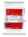
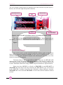
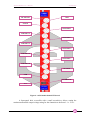
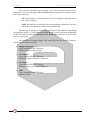
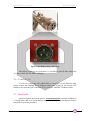
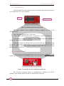
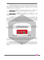
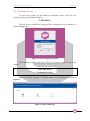
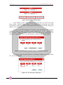
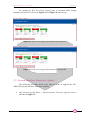
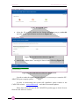
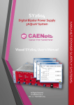
High-Voltage ADAPTive Optics Supply System User’s Manual All Rights Reserved © CAEN ELS d.o.o. Rev. 1.3 – October 2014 BEAMLINE ELECTRONIC INSTRUMENTATION HV-ADAPTOS CAEN ELS d.o.o. Kraška ulica, 2 6210 Sežana – Slovenija Mail: [email protected] Web: www.caenels.com 2 Table Of Contents 1. INTRODUCTION................................................................................................ 8 1.1 1.2 2. HV-ADAPTOS OVERVIEW ............................................................................ 8 A1522 HV BOARD ........................................................................................ 10 HARDWARE INSTALLATION...................................................................... 13 2.1 SAFETY AND OPERATION REQUIREMENTS .................................................... 13 2.1.1 General Information ................................................................................ 13 2.1.2 Injury Precautions ................................................................................... 13 2.1.3 Product Damage Precautions .................................................................. 14 2.1.4 EC Certifications and Compliance .......................................................... 14 2.1.5 Term Definitions ...................................................................................... 14 2.1.6 Safety Terms and Symbols ....................................................................... 14 2.2 POWER RATINGS ........................................................................................... 15 2.3 INITIAL INSPECTION ...................................................................................... 16 2.4 RACK MOUNTING ......................................................................................... 16 2.5 POWER CONNECTION .................................................................................... 16 2.6 CONNECTIVITY ............................................................................................. 17 2.7 INTERLOCKS.................................................................................................. 17 2.7.1 Board Interlock ........................................................................................ 18 2.7.2 System Interlock ....................................................................................... 18 2.8 RESET ........................................................................................................... 19 3. QUICK START .................................................................................................. 20 3.1 SYSTEM POWER-ON ...................................................................................... 20 3.2 SYSTEM ACCESS ........................................................................................... 21 3.2.1 Crate Map ................................................................................................ 22 3.2.2 Group Configuration ............................................................................... 22 3.2.3 Group Control .......................................................................................... 25 3.3 SYSTEM INTERFACE FIRMWARE UPDATE ...................................................... 31 4. TECHNICAL SPECIFICATIONS .................................................................. 33 Document Revision 1.0 1.1 Date February 25th 2014 March 3rd 2014 1.2 July 4th 2014 1.3 October 29th 2014 Comment Manual first release Interlock information and technical data added Information on the FW update added Manual graphics changed 4 HV-ADAPTOS User’s Manual Safety information - Warnings CAEN ELS will repair or replace any product within the guarantee period if the Guarantor declares that the product is defective due to workmanship or materials and has not been caused by mishandling, negligence on behalf of the User, accident or any abnormal conditions or operations. Please read carefully the manual before operating any part of the instrument WARNING High voltage inside, DO NOT open boxes CAEN ELS d.o.o. declines all responsibility for damages or injuries caused by an improper use of the Modules due to negligence on behalf of the User. It is strongly recommended to read thoroughly this User's Manual before any kind of operation. CAEN ELS d.o.o. reserves the right to change partially or entirely the contents of this Manual at any time and without giving any notice. Disposal of the Product The product must never be dumped in the Municipal Waste. Please check your local regulations for disposal of electronics products. 5 HV-ADAPTOS User’s Manual Read over the instruction manual carefully before using the instrument. The following precautions should be strictly observed before using the HVADAPTOS bipolar power supply system: WARNING CAUTION Do not use this product in any manner not specified by the manufacturer. The protective features of this product may be impaired if it is used in a manner not specified in this manual. Do not use the device if it is damaged. Before you use the device, inspect the instrument for possible cracks or breaks before each use. Do not operate the device around explosives gas, vapor or dust. Always use the device with the cables provided. Turn off the device before establishing any connection. Do not operate the device with the cover removed or loosened. Do not install substitute parts or perform any unauthorized modification to the product. Return the product to the manufacturer for service and repair to ensure that safety features are maintained This instrument is designed for indoor use and in area with low condensation. 6 HV-ADAPTOS User’s Manual The following table shows the general environmental requirements for a correct operation of the instrument: 7 Environmental Conditions Requirements Operating Temperature 5°C to 40°C Operating Humidity 30% to 85% RH (non-condensing) Storage Temperature -10°C to 55°C Storage Humidity 5% to 90% RH (non-condensing) Introduction HV-ADAPTOS User’s Manual 1. Introduction This document is the manual for the HV-ADAPTOS multi-channel power supply system and cointains basic information about the installation, the configuration and the use of the system. 1.1 HV-ADAPTOS Overview The HV-ADAPTOS is a multi-channel High-Voltage (HV) bipolar power supply system especially developed to control, monitor and safely operate bimorph mirrors. The system is composed by a standard 19” - 4U crate containing a CPU board, integrated cooling, power supply sources and the HV boards. Up to 6 independent A1522 HV boards, each one housing 8 channels – rated at ± 2kV @ ± 0.5mA – can be installed into the system crate. Every HV board has dedicated internal protections that limit differential voltage between adjacent channel outputs to 500V. This behavior is required in order to protect the mirror from damages and it allows safe operation of the overall optical system. Each A1522 board also has an OVP (Over Voltage Protection) output and an OVP input connector in order to daisychain the differential protection – i.e. 500V – between channels of different boards. Other hardware-dedicated protections – e.g. passive emergency output discharging – are implemented for the specific application. The HV-ADAPTOS system includes an internal web server software dedicated to bimorph mirror control and monitoring and allows to simultaneously control more than one mirror with a single system. The 8-channel boards can also be collected into different groups, each one associated with 8, 16, 24 or 32 number of electrodes. Three different levels of users’ privileges (power user, user and generic) with different features and accessibility to configuring-setting reading are implemented. The possibility to dynamically assign individual HV channels to “superelectrodes” within the same group is also provided. Communication to the HVADAPTOS system is guaranteed by means of a 10/100/1000 Ethernet interface over standard TCP-IP protocol. EPICS drivers are integrated into the system crate and easily allow interfacing to the control system. The system also includes proprietary creep and hysteresis control and minimization routines. 8 HV-ADAPTOS User’s Manual Introduction HV-channels connected to the same mirror move in a coordinated manner in order not to make OVP trip during set point changes. External interlocks – e.g. vacuum – are accessible and configurable. Front view of HV-ADAPTOS power supply system dedicated to optics is shown in Figure 1. Figure 1: front view of the HV-ADAPTOS system crate Front view of the system, as well as indication of main features is shown in the following Figure 2. The system is composed by a Primary Power Supply and by a CPU module, both embedded in the crate and that can be easily replaced without having to perform difficult operations. CPU Module Primary Power Supply Figure 2: front view of HV-ADAPTOS and its composing parts An overview of the rear panel of the system is hereafter presented in Figure 3. 9 HV-ADAPTOS User’s Manual Introduction The A1522 High-Voltage boards are installed in the crate from the rear panel (up to 6 boards, each one with eight independent channels). A1522 HV Boards Fuse Earth Main Switch AC Mains Input Figure 3: rear view of HV-ADAPTOS with two (2) installed A1522 HV boards Two A1522 High-Voltage boards, as well as the AC Mains Input (with the fuse holder), an additional earth connection, and the Main switch are clearly visible in Figure 3. 1.2 A1522 HV Board The A1522 board is a multi-channel board that cointains eight (8) independent high-voltage channels described in Figure 4. Up to six (6) different boards can be installed in the same HV-ADAPTOS system crate, allowing the maximum size of the system to reach 48 HV channels. The high-voltage is fed to eight different SHV connectors; the HV ON LED indicates that at least one of the high-voltage channels of the board is enabled. The over-voltage protections OVP IN and OVP OUT can be used to extend the protection of 500V maximum differential voltage between adjacent channels to adjacent boards. Please note that OVP IN is referred to CHANNEL 1 and OVP OUT to CHANNEL 8 of the same board. By connecting the OVP OUT of one A1522 board to the OVP IN of another board then the maximum voltage difference between CHANNEL 8 of one board and CHANNEL 1 of the other board is hardware-limited to 500V. 10 HV-ADAPTOS User’s Manual HV ON LED Introduction GND OVP IN CHANNEL 1 CHANNEL 2 CHANNEL 3 CHANNEL 4 CHANNEL 5 CHANNEL 6 CHANNEL 7 CHANNEL 8 OVP OUT GND INTERLOCK VMAX Figure 4: A1522 multi-channel HV board A front-panel hole, accessible with a small screwdriver, allows setting the maximum allowable output voltage rating for the channels on the board – i.e. VMAX. 11 HV-ADAPTOS User’s Manual Introduction Two external interlocks are accessible via a 4-pin connector placed on the front panel. They are indicated as SIG and PASS and are respectively a passive and a dry-contact interlock: - SIG: this interlock is activated when a TTL-level signal is applied between the + and – contacts; - PASS: this interlock is activated if the corresponding contacts are left open and needs to be shorted in order to activate the board. The tripping of at least one of the interlocks turns all the channels of the board off and lights up the red LED indicated as ILCK; this event would turn the HV ON LED off so that obviously the HV ON and the ILCK light cannot be on at the same time for any reasons. All connectors of output voltage, OVP and GND, the type and the respective function are hereafter presented: Output Connectors Type: Radiall SHVR317580-type Function: High-Voltage Output OVP output Type: Radiall SHVR317580-type Function: Output (referred to Channel 8) OVP input Type: Radiall SHVR317580-type Function: Input (referred to Channel 1) GND Type: Radiall SHVR317580-type Function: GND 12 HV-ADAPTOS User’s Manual Hardware Installation 2. Hardware Installation 2.1 Safety and Operation Requirements This section contains the fundamental safety rules for the installation and operation of the HV-ADAPTOS system. Read thoroughly this section before starting any procedure of installation or operation of the product. 2.1.1 General Information Review the following safety precautions to avoid injury and prevent damage to this product or any products connected to it. To avoid potential hazards, use the product only as specified. Only qualified personnel should perform service procedures. 2.1.2 Injury Precautions Please read carefully this list: use Proper Power Cord and HV Cables; to avoid fire hazard, use only the power cord and HV cables specified for this product; avoid Electric Overload; to avoid electric shock or fire hazard, do not apply a voltage to a load outside the range specified for that load; avoid Electric Shock; to avoid injury or loss of life, do not connect or disconnect cables while they are connected to a voltage source; ground the Product; This product is grounded through the grounding conductor of the power cord. To avoid electric shock, the grounding conductor must be connected to earth ground. Before making connections to any input or output terminals of the product, ensure that the product is properly grounded; do Not Operate Without Covers; 13 Hardware Installation HV-ADAPTOS User’s Manual to avoid electric shock or fire hazard, do not operate this product with covers or panels removed; do Not Operate in Wet/Damp Conditions; to avoid electric shock, do not operate this product in wet or damp conditions; do Not Operate in an Explosive Atmosphere; to avoid injury or fire hazard, do not operate this product in an explosive atmosphere; a minimum distance of 15cm is required between the top of a crate and any other object over it. 2.1.3 - Product Damage Precautions Use Proper Power Source; Do not operate this product from a power source that applies more than the voltage specified; To prevent product overheating, do not obstruct cooling fans vents; Do Not Operate With Suspected Failures; If you suspect there is damage to this product, have it inspected by qualified service personnel. 2.1.4 EC Certifications and Compliance Use in conformity of the definition with fully equipped mainframe with fully closed slots by boards or dummy panels. Sufficient cooling and mains connection must be secured according to regulations. Signal lines length during all tests was less than 3 meters. Admitted for powering by industrial mains only. 2.1.5 Term Definitions WARNING: warning statements identify conditions or practices that could result in injury or loss of life; CAUTION: caution statements identify conditions or practices that could damage this product or other property. 2.1.6 Safety Terms and Symbols The following terms may appear on the product or in some product description: 14 HV-ADAPTOS User’s Manual Hardware Installation DANGER: indicates an injury hazard immediately accessible as you read the marking; WARNING: indicates an injury hazard not immediately accessible as you read the marking; CAUTION: indicates a hazard to property including the product. 2.2 Power Ratings The following label is present on the rear panel of the HV-ADAPTOS power supply system: The meanings of the following symbols are: DANGER High Voltage ATTENTION Refer to Manual Please note that the maximum cable length that can be connected to the A1522 HV boards depends on the cable specifications. The HV-ADAPTOS system is provided with 25 A tolerant power cord, suitable to the specific system configuration requirements, as reported on the following back panel label: VOLTAGE RANGE FREQUENCY INPUT POWER 100 / 230 VAC 50 - 60 Hz 2500 W Max Up to 6 independent A1522 HV boards, each one housing 8 channels – rated at ± 2kV @ ± 0.5mA – can be installed into a single system crate. Each HV board has dedicated internal protections that limit the voltage difference between adjacent channel outputs to 500V. 15 Hardware Installation HV-ADAPTOS User’s Manual 2.3 Initial Inspection Prior to shipment this unit was inspected and found free of mechanical or electrical defects. Upon unpacking of the unit, inspect for any damage, which may have occurred in transport. The inspection should confirm that there is no exterior damage to the unit, such as broken knobs or connectors, and that the panels are not scratched or cracked. Keep all packing material until the inspection has been completed. If damage is detected, file a claim with carrier immediately and notify the producer. Before installing the system, make sure you have read thoroughly the safety rules and installation requirements, then place the package content onto your bench; you shall find the following parts: HV-ADAPTOS system crate; Primary Power Supply; already installed in the crate; CPU Board; already installed in the crate; AC Mains power cord; 10 BASE-T Ethernet cable Moreover, in order to fully operate the HV-ADAPTOS, an external Personal Computer and (at least) one A1522 High-Voltage Board are also required. The boards are already installed in the system in order to form the desired HVADAPTOS configuration (e.g. HV-ADAPTOS32 for a 32-channels system, with four A1522 HV boards installed in the crate). 2.4 Rack Mounting The HV-ADAPTOS is equipment for BUILDING-IN: it must be installed in a standard 19” rack cabinet. Use the front panel four mounting brackets in order to install the unit in the rack. 2.5 Power Connection In order to power up the HV-ADAPTOS system please follow these steps with the AC Mains always disconnected from the wall plug. Plug the Power Supply Cord into the CA-COM-E-20-19 3-Pin Cannon Industrial AC Input rear panel connector; both of them are shown in Figure 5. 16 HV-ADAPTOS User’s Manual Hardware Installation Figure 5: AC Mains mating connections Once these operations are performed it is possible to proceed and connect the AC power cable into the Mains wall plug. 2.6 Connectivity In order to connect the HV-ADAPTOS to a host PC via the Ethernet link, please connect the standard RJ-45 Ethernet socket port placed on the system CPU module to the relevant port of the host PC by using the 10BASE-T Ethernet cable. 2.7 Interlocks Interlock signals, that can be used as vacuum interlocks, are both available on a “board”-basis and on a system-basis in the HV-ADAPTOS. A description of these interlocks is hereafter presented. 17 HV-ADAPTOS User’s Manual Hardware Installation 2.7.1 Board Interlock Interlock signals for each single board are accessible on the module front panel on an AMP 280371-2 4-pin connector. Pin 1 Interlock LED Figure 6: Interlock connector of the board The output channels can be enabled, referring to Figure 6, in one of the following ways: Pins 3-4 short-circuited, pins 1-2 left open +5V (3-4mA) applied between pin 1 (+) and pin 2 (–), pins 3-4 left open If the channel outputs are enabled, i.e. one of the two previous conditions is verified, the interlock red LED is turned off. When the channels are disabled after an interlock trip, the LED turns on and the voltage outputs of the channels drop to zero at the factory-defined slew rate; the interlock condition is latching so that the channels remain OFF until the user turns them ON again via software. 2.7.2 System Interlock A global system interlock signal that can also be used as a vacuum interlock signal is present on the HV-ADAPTOS system crate front panel as shown in Figure 7. Figure 7: Interlock of the HV-ADAPTOS system crate The interlock command allows to simultaneously switching off all the channels of the boards installed in the HV-ADAPTOS system crate. 18 HV-ADAPTOS User’s Manual Hardware Installation The interlock functionality can be activated via the interlock input which acts as an open/closed contact. The selection of the contact position (open or closed) which will cause the INTERLOCK command is performed via the two-position switch placed on the crate front panel: Upper position (OPEN): the channels are switched off as the INTERLOCK contact is open (the ground connection in the INTERLOCK input is removed); Lower position (CLOSED): the channels are switched off as the INTERLOCK contact is closed (the INTERLOCK input is grounded – short circuited). An INTERLOCK trip condition of the system is visually signalled by the interlock red LED. This condition, as the one previously described for the single board interlock, is latching so that in order to turn the channels on again, the user must remove the interlock condition that caused it to trip. Any attempt to turn the channels on without removing the INTERLOCK condition will result unsuccessful. 2.8 Reset The RESET command allows via the reset input signal or via the reset pushbutton to reset the system CPU. The RESET input signal and the corresponding pushbutton is shown in Figure 8. Figure 8: Reset of the HV-ADAPTOS internal CPU RESET Signal: if the input signal is at high logic level (TTL) only the CPU is reset and the whole system resumes its operation from the beginning. All the channels which are ON remain ON, channels which are OFF remain OFF; RESET Push-Button: if the pushbutton is pressed and the released only the CPU is reset and the whole system resumes its operation from the beginning. All the channels which are ON remain ON, channels which are OFF remain OFF “long” pressure. 19 HV-ADAPTOS User’s Manual Quick Start 3. Quick Start A quick presentation on how to turn on the HV-ADAPTOS system and how to operate it in few steps is herein presented. 3.1 System Power-On In order to power on and to handle the HV-ADAPTOS system locally, please follow these simple steps: plug the A1522 high-voltage boards into the system crate and fix them properly (as shown in Figure 9); Figure 9: A1522 high-voltage boards installation switch on the host PC; configure the host PC as a DHCP client; set the dual-pole main switch on the rear panel of the crate to position “1” to power up the system; set the POWER-ON key, placed on the Primary Power Supply panel, on down position (i.e. LOCAL). 20 HV-ADAPTOS User’s Manual Quick Start 3.2 System Access To access the system via the Ethernet connection, please open the web browser and type the default IP address 192.168.0.1 The web browser should now open the Web Configurator Log-In window, as shown in Figure 10. Figure 10: Web Configurator Log-In The following default access keys have to be used in order to access the system: User ID: admin Password: admin After successfully logging in, the Main Menu will be displayed as shown in Figure 11: Figure 11: Main Menu page 21 HV-ADAPTOS User’s Manual Quick Start Main Menu has the following three options: Crate Map, Group Config and Group Control. A brief description of these options is herein presented, together with some screenshots: 3.2.1 Crate Map The Crate Map shows what types of boards are inserted into the crate and in which slot they are plugged, as shown in Figure 12: Figure 12: Crate Map page In the previous sample screenshot, two high-voltage boards A1522 are installed in the HV-ADAPTOS crate, in slot 2 and slot 3 respectively. Each board serial number and installed firmware version is also displayed in this page. 3.2.2 Group Configuration The Group Configuration allows creating and configuring groups of highvoltage channels. 22 HV-ADAPTOS User’s Manual Quick Start Figure 13: Status Summary page The configuration of groups can be checked directly from the Status Summary section. The Boards View Tab monitors the boards that are installed in the crate and shows if they are assigned to a specific group and what particular channels are enabled. A green FREE tag is displayed if a board is not assigned to any group while a red MISSING BOARD one is displayed if the board previously assigned to a group is removed. This page does not update automatically its content so that it is necessary to refresh it if some modifications are applied and the displayed values updated. Note: an “enabled” channel can be set and monitored on the control page of the corresponding group. When a power ON of the group is performed, all the boards belonging to that group are powered on and the “disabled” channels reach the same voltage of the last “enabled” channel. The Group Editor section contains some information about the created groups (please note that the group creation is not allowed to the final users). Two pushbuttons are present in this section: the one marked with the group name gives access to modifications on the corresponding groups, as shown in Figure 14, while the “Edit” button (under the Superchannel column) opens a dialog box that allows creation and modification of the superchannels connected to that group. The page for the group modification permits to the user (i.e. admin) to modify the group name and to add or remove the enabled channels. Note: if a change in the configuration of some enabled channels that are placed on different boards is performed, it is necessary to verify and eventually change the hardware connections dedicated to the protection of 500V maximum differential voltage between adjacent channels. 23 HV-ADAPTOS User’s Manual Quick Start Figure 14: Edit Group page A screenshot of the dialog box with the Superchannel configurator is shown in Figure 15. The configuration the superchannels can be performed using this box: in order to create a superchannel it is necessary to click on the desired checkbox – i.e. to link two channels – and then to push on the “Set” button. Figure 15: Superchannel configurator pop-up box By clicking on the “Reset” button, all the previously configured superchannels are canceled. The Groups View tab is shown in Figure 16 and gives access to the screen showing the superchannels that are configured for each group. 24 HV-ADAPTOS User’s Manual Quick Start Figure 16: Groups View tab 3.2.3 Group Control The Group Control Page allows for controlling a mirror (or a pre-defined group of electrodes) using the system internal features. Monitoring of the output voltage is also visible on this page, as the results of the module internal Analog-toDigital Converters (ADCs) readback. Figure 17 (A,B,C): Groups View tab 25 Quick Start HV-ADAPTOS User’s Manual In this section it is possible to check the created groups and it is also possible to explore their content – i.e. the group channels and the output voltage – by clicking over the corresponding group name. The case of a group with no superchannels configured is captured on Figure 17A, the one when two superchannels are configured is shown in Figure 17B while the situation with the same two superchannels configured and turned ON is represented in Figure 17C. The configured superchannels are indicated with a GREEN colour and with an “S” prefix letter before its number – e.g. S2 and S4. The background colour for the voltage value of each channel can be one of the following: no color (or WHITE): the channels are OFF; BRIGHT GREEN: the channels are turned ON; DARK GREEN: the channels are in the process of being turned off; YELLOW: a warning condition is ongoing; RED: an error or alarm situation has happened. The user and admin types of users can access to some additional controls by clicking on the “Advanced options” pushbutton on the Group Control page. A variety of things can be performed by accessing this page, shown in Figure 18; some of them are: turn ON and turn OFF the group; set and monitor the channel output voltages; store target voltages on each channel (that can be recalled later); monitor the status and faults/errors of channels; change the operational mode; monitor the information on the board of the group, mainly in order to monitor the temperature; change the speed of the fans in the crate. 26 HV-ADAPTOS User’s Manual Quick Start Figure 18: advanced options of the Group Control section The first line that is displayed on this page (and in Figure 18) contains some indicators that are hereafter listed: 27 Connectivity: this indicator is green when there is a connection between the system and the browser. When this connection is not present, it becomes red; Ready: this indicator is green when it is possible to send command to the corresponding group while it is yellow when some operation is performed – e.g. turning ON, voltage changing, etc.; Alarm: this indicator is white under normal conditions and it becomes red after and alarm event. It is necessary to send the Clear Alarm command (by clicking on the specific button) in order to remove the alarm condition; Last updated: this indicator shows the date and time of the last performed update every 3 seconds (in non-busy conditions). The system date and time can be set in the Settings menu. If no updates are received for a longer period (between 20 and 30 seconds), the time string background color becomes red. HV-ADAPTOS User’s Manual Quick Start Each channel of the group has a box that cointains certain information, as shown in Figure 19: Figure 19: screenshot of the channels information Status: OFF, ON, Up/Down, Busy, Pwr Off, etc. The background is white if the channel is turned off, bright green if it is on and in the ramping process, dark green when it is turning off and red when a problem occurrs (UNV = UNder Voltage, OVV = OVer Voltage, EXT-TRIP = generated by the crossing of a current threshold that in a chain alarms all channels); VOut (V): indicates the channel output voltage; a small chart that shows the voltage behavior; Target (V): indicates the target voltage set for this channel. A GREEN line bordering the voltage value, as shown in all channels and superchannels of Figure 19, indicates that the one displayed is the voltage effectively set on that channel while a RED line border means that the voltage set to that channel is not compliant with the voltages set on the adjacent channels. In this last case – i.e. RED border – the “Set All Target” option will be automatically disabled. All this information is shown in the interface by means of a tooltip that is displayed when stopping with the mouse cursor over the voltage value. the “wrench” button on the bottom left of each channel/superchannel opens a dialog box that allows the setting of the voltage values for the HV channel. This dialog box is shown in Figure 20. Voltages can be set either in with an absolute value – Set (V) – or with an absolute value – Shift (V). The Target Voltage can also be set from this box – i.e. Trgt (V). 28 HV-ADAPTOS User’s Manual Figure 20: the “wrench” Quick Start dialog box (e.g. superchannel 2) the “zoom” button (only for superchannels) gives access to a dialog box that indicates that presents the channels associated to the superchannel. This dialog box is shown in Figure 21. Figure 21: the “zoom” dialog box (e.g. superchannel 2) A blinking RED dot – i.e. • – is displayed on each channel or superchannel in order to indicate its “busy” status. In the section under the channels there is a toolbar with a few buttons that allow to showing or hiding some additional sections – e.g. board information, as shown in Figure 22, or information about the fan operation. 29 Quick Start HV-ADAPTOS User’s Manual Figure 22: board information section In the bottom section of the Group Control page there are some boxes that allow setting a global output voltage on all channels and performing some other operations as turning ON/OFF, the operation mode, the fan speed and clearing all alarms (“Clear Alarm”). As soon as the ON command is executed, a box requesting if the channels needs to be turned on at the set values or at zero voltage level – i.e. 0V – appears. This box is shown in Figure 23 and the voltages can be set all to zero by clicking the “Set all to zero” button while can be left untouched by clicking on the “Keep” button. Figure 23: box for applying output voltages at channel turning ON The button “Store Trg All” allows to set all target voltages on a single dialog box, shown in Figure 24. Figure 24: “Set All Target” dialog box 30 HV-ADAPTOS User’s Manual Quick Start An example on how the Group Control page is presented while turning channels ON and OFF is shown in Figure 25 and Figure 26 respectively. Figure 25: Group Control page while channels are turning ON Figure 26: Group Control page while channels are turning OFF 3.3 System Interface Firmware Update The following procedure needs to be done in order to upgrade the HVADAPTOS System Interface Firmware remotely: 31 click on the Upgrade Menu -> System Interface Firmware Upgrade icon as indicated in Figure 27; HV-ADAPTOS User’s Manual Quick Start Figure 27: Upgrade Menu select the file to load, which has the format: hv-adaptos_sys_x.y.z-date.bin and click on the Upload button as shown in Figure 28; Figure 28: System Interface firmware upgrade wait for the “update done!” message as shown in the following Figure 29; Figure 29: successful interface firmware update screen In order to make the update become effective it is necessary to restart the HVADAPTOS power supply system. In order to acknowledge the system full capabilities please connect to the CAEN ELS website – www.caenels.com – and check for manual updates. Please also refer to the specific HV-ADAPTOS product page to check for new firmware and software releases. 32 HV-ADAPTOS Quick Start Guide Technical Specifications 4. Technical Specifications Specifications for the HV-ADAPTOS multichannel high-voltage power supply dedicated to optics are hereafter listed: HV-ADAPTOS (with A1522-ADAPTOS boards) Rated Output Voltage ±2 kV (per channel) Rated Output Current ±0.5 mA (per channel) Rated Output Power Input Ratings High-Voltage Channels Boards Setting Resolution 1 W (per channel) 100-230 VAC @ 50/60Hz 8 per board up to 6 boards / system – i.e. 48 channels 75 mV Output Noise and Ripple < 10 mVpk-pk Long Term Stability (8h) < 50 ppm/FS Temperature Coefficient < 50 ppm/FS VMAX Hardware ±2.3 kV VMAX Hardware Accuracy ±2% of FS VMAX Software Resolution 1V Ramp Up/Down Ramp Up/Down Step 1-500 V/s 1V Voltage Set vs. Output Voltage Accuracy ±(0.02% of setting + 1 V) Voltage Monitor vs. Output Voltage Accuracy ±(0.02% of reading + 1 V) Current Monitor vs. Output Current Accuracy ±50 nA Hardware Protections Cooling Communication 33 500V differential voltage between adjacent channels External interlocks Integrated forced air convection 10/100/1000 Ethernet TCP-IP HV-ADAPTOS User’s Manual Technical Specifications Internal Web Server with different users’ privileges: Control Software Mechanical Dimensions - Power user User Generic 19” × 4U × 667 mm crate 34