
1
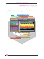
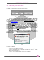
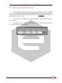
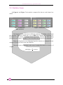
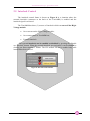
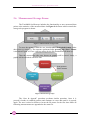
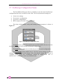
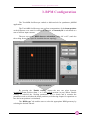
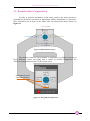
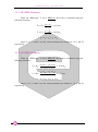
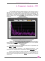
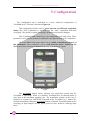
All Rights Reserved © CAEN ELS d.o.o. Rev. 1.0 – February 2015 1 BEAMLINE ELECTRONIC INSTRUMENTATION TetrAMM Oscilloscope Quick Start Guide TetrAMM Oscilloscope - Quick Start Guide Table of Contents 1. INTRODUCTION................................................................................................ 5 2. OSCILLOSCOPE OVERVIEW ........................................................................ 6 2.1 CONNECTING TO THE TETRAMM ................................................................... 7 2.2 ACQUISITION OPTIONS .................................................................................... 8 2.3 HIGH-VOLTAGE MODULE OPTIONS ................................................................ 9 2.4 STATISTICS FRAME ........................................................................................ 10 2.5 INTERLOCK CONTROL ................................................................................... 11 2.6 MEASUREMENT STORAGE FRAME ................................................................. 12 2.6.1 Example of Saved Data Points ................................................................. 13 2.6.2 Example of Saved Statistics ..................................................................... 13 2.7 OSCILLOSCOPE CONFIGURATION FRAME ...................................................... 14 3. BPM CONFIGURATION ................................................................................. 15 3.1 BEAM POSITION COMPUTATION .................................................................... 17 3.1.1 90° BPM Geometry .................................................................................. 18 3.1.2 45° BPM Geometry .................................................................................. 18 4. FREQUENCY ANALYSIS - FFT .................................................................... 19 5. CONFIGURATION ........................................................................................... 20 2 TetrAMM Oscilloscope - Quick Start Guide Table of Figures Figure 1: TetrAMM Oscilloscope main window ........................................................... 6 Figure 2: Communication configuration frame ............................................................. 7 Figure 3: Pop-up window for failed connection ............................................................ 7 Figure 4: TetrAMM acquisition options ........................................................................ 8 Figure 5: TetrAMM High-Voltage module options....................................................... 9 Figure 6: Statistics for BPM calculation ..................................................................... 10 Figure 7: Statistics for currents .................................................................................... 10 Figure 8: Interlock control frame ................................................................................. 11 Figure 9: Measurement storage frame ......................................................................... 12 Figure 10: Data storage steps ....................................................................................... 12 Figure 11: Oscilloscope configuration frame .............................................................. 14 Figure 12: BPM tab ...................................................................................................... 15 Figure 13: BPM channel selector ................................................................................. 17 Figure 14: Wrong BPM configuration ......................................................................... 17 Figure 15: FFT tab ....................................................................................................... 19 Figure 16: Configuration tab ........................................................................................ 20 3 TetrAMM Oscilloscope - Quick Start Guide Document Revision 1.0 Date February 20th, 2015 Comment First release 4 TetrAMM Oscilloscope - Quick Start Guide 1. Introduction This Quick Start guide describes the basic functionality of the TetrAMM oscilloscope software. The main purpose of this document is to introduce users to user interface, presenting the steps needed to operate the TetrAMM device and to explain some more advanced features. The users are strongly encouraged to read the TetrAMM User’s Manual since it explains some features of device in more detail. 5 TetrAMM Oscilloscope - Quick Start Guide 2. Oscilloscope Overview The Figure 1 marks different configuration modules. The following chapter explains each one of the sections in detailed way. Acquisition configuration (page 8) Interlock Communication configuration (page 7) control (page 11) Graph tab selector Oscilloscope config. frame (page 14) Figure 1: TetrAMM Oscilloscope main window Graph controls Statistics frame (page 10) Measurement storage frame (page 12) High Voltage controls (page 9) 6 TetrAMM Oscilloscope - Quick Start Guide 2.1 Connecting to the TetrAMM On Figure 2 communication configuration frame is shown. Figure 2: Communication configuration frame The first step before connecting to the TetrAMM is to set the IP address and TCP port. The default factory values for TetrAMM are 192.168.0.10 and 10001. The IP and TCP settings can be changed using the CAENels Device Manager software, available at www.caenels.com. Once the correct values are entered into the Address and Port fields, by pressing the Connect button makes Oscilloscope to establish connection with the device and it will start the acquisition loop. During the acquisition loop the Oscilloscope reads the device and the HV module status, updates configuration if needed, captures data from the picoammeter and shows it on a graph. It continues performing this loop until the Stop button is pressed. In the case that the TetrAMM device does not respond (because the address or port is not correctly set or the device is, for example, turned off) the window on Figure 3 will pop-up. Figure 3: Pop-up window for failed connection In this case we suggest: 7 Check if the TetrAMM is powered on; Check if the Ethernet cable is connected (verify that the “Link LED” on the RJ45 connector is turned on); Check IP and TCP settings using CAENels Device Manager. TetrAMM Oscilloscope - Quick Start Guide 2.2 Acquisition Options On Figure 4 the configuration for acquisition are shown. User can select input range, number of channels and the size of acquisition window. At start-up the TetrAMM sets all channels to the highest measuring range in order to protect the analog front-end from unwanted large currents. User can change this setting by selecting the desired or appropriate range from the drop-down menu (see the TetrAMM User’s Manual for a full description of auto-ranging functionality). The acquisition window determines the length of the captured buffer which is shown on the graphs and on which the statistics are calculated. When the averaging is disabled (see Chapter 5 on page 20) this value is limited to maximum of 4 s. Figure 4: TetrAMM acquisition options 8 TetrAMM Oscilloscope - Quick Start Guide 2.3 High-Voltage Module Options Configuration parameters for the High-Voltage module are shown on Figure 5. The user can enable and disable the HV module and set the desired voltage. The voltage and current read-back values are also shown. The HV Status LED indicates if the module is turned on or not. At start-up the TetrAMM device disables the High-Voltage module output for safety reasons. The voltage setpoint value is limited by the HV module model installed in TetrAMM (different voltage ratings). Figure 5: TetrAMM High-Voltage module options 9 TetrAMM Oscilloscope - Quick Start Guide 2.4 Statistics frame On Figure 6 and Figure 7 the statistics computed for data on each channel are shown. Figure 7: Statistics for currents Figure 6: Statistics for BPM calculation The Statistics frame exists in two different variations, depending on the Graph tab selection. When the Graph tab is set to BPM, the statistics are calculated on horizontal X and vertical Y position and on the beam intensity I0. The Scaling parameters (see Chapter 3 on page 15) are also taken into account in the computation. When the Graph tab is set to Current Graph the statistics are computed on the measured currents on each of the four channels. The noise value is calculated as the ratio of standard deviation σ to mean µ of a signal. 𝑁𝑆𝑅 [%] = 𝜎 ∗ 100 % 𝜇 10 TetrAMM Oscilloscope - Quick Start Guide 2.5 Interlock Control The interlock control frame is shown on Figure 8 in a situation where the external interlock (connector at the back of the TetrAMM) is enabled and the interlock signal is activated. The TetrAMM has three (3) sources of interlock which can turn off the HighVoltage module: Over-current on the High Voltage module; Over-temperature in TetrAMM box; External interlock. The external interlock can be enabled or disabled by pressing the “Enable ext. interlock” button. When the external interlock gets activated, it can be cleared by clicking on “Reset interlock” button. The HV module can be re-enabled only after interlock has been cleared. Figure 8: Interlock control frame 11 TetrAMM Oscilloscope - Quick Start Guide 2.6 Measurement Storage Frame The TetrAMM Oscilloscope includes the functionality to store measured data points or the statistics of the measured data. On Figure 9 the frame which controls the storage sub-program is shown. Figure 9: Measurement storage frame To store the measured data the user should select the desired format (either data points or statistics). The sequence performed after pressing the “Save” button is shown on Figure 10. First, a pop-up asking for the file destination will show up. Then the current data (the ones shown on graphs) will be saved. Lastly, a graphs will be refreshed with new data. Acquistion User presses “Save” button Show next data File pop-up Save current data Figure 10: Data storage steps The “Save & Append” procedure performs similar operation. Once it is pressed it latches in enabled position and continues to store data until it is pressed again. The user is asked to define or locate the file name for the first time while all following measurements are appended to the same file. 12 TetrAMM Oscilloscope - Quick Start Guide 2.6.1 Example of Saved Data Points LabVIEW Measurement Writer_Version 2 Reader_Version 2 Separator Tab Decimal_Separator . Multi_Headings No X_Columns One Time_Pref Relative Operator Jan Date 2015/02/18 Time 14:41:27.7471370697021484375 ***End_of_Header*** Channels 4 Samples 10000 10000 10000 10000 Date 2015/02/18 2015/02/18 2015/02/18 2015/02/18 Time 14:41:27.7471370697021484375 14:41:27.7471370697021484375 14:41:27.7471370697021484375 14:41:27.7471370697021484375 X_Dimension Time Time Time Time X0 0.0000000000000000E+0 0.0000000000000000E+0 0.0000000000000000E+0 0.0000000000000000E+0 Delta_X 0.000100 0.000100 0.000100 0.000100 ***End_of_Header*** X_Value CH1 CH2 CH3 CH4 Comment 0.000000 3.509047E-12 3.902240E-12 3.094912E-12 -3.871873E-13 0.000100 4.796508E-12 3.303214E-12 2.102495E-12 -4.959658E-13 0.000200 7.089796E-12 3.559514E-12 8.910301E-13 8.615300E-13 0.000300 3.051582E-12 2.246721E-12 -1.746475E-12 7.795736E-13 0.000400 2.695444E-12 3.863497E-12 -1.016319E-12 1.871829E-12 0.000500 4.045489E-12 1.623853E-12 1.415551E-12 1.840536E-12 0.000600 5.611601E-12 3.581865E-12 2.545059E-12 4.234359E-13 0.000700 5.730810E-12 3.188475E-12 1.199484E-12 1.037364E-12 2.6.2 Example of Saved Statistics -----------------------------------------------------------------TetrAMM measurement statistics Date: 2/18/2015 Time: 2:42:11 PM -----------------------------------------------------------------CH1: mean: 4.408513E-13 st dev: 3.234769E-12 noise:7.337552E+2 CH2: mean: 4.279575E-13 st dev: 2.224902E-12 noise:5.198885E+2 CH3: mean: 5.176757E-13 st dev: 1.861195E-12 noise:3.595291E+2 CH4: mean: 5.963117E-14 st dev: 1.936945E-12 noise:3.248210E+3 13 TetrAMM Oscilloscope - Quick Start Guide 2.7 Oscilloscope Configuration Frame The TetrAMM oscilloscope offers a possibility to store the actual Oscilloscope configuration that can be recalled at a later time. The saved parameters/settings are: Connection settings; Picoammeter configuration; Acquisition configuration; BPM configuration and scaling parameters. The frame which enables saving and loading settings/paramters is shown in Figure 11. Figure 11: Oscilloscope configuration frame The Save button opens a file selection pop-up which enables the user to select the file in which to save the current Oscilloscope configuration. The Load button enables user to load some previously saved configuration. The Set Default button enables user to save the current settings as a default settings which are loaded at the start-up. Since the default settings file is saved in “Program Files” folder the Oscilloscope should be started with “Run as administrator” command in order to perform this task. 14 TetrAMM Oscilloscope - Quick Start Guide 3. BPM Configuration The TetrAMM Oscilloscope embeds a dedicated tab for quadrature phBPM application. The TetrAMM Oscilloscope can perform computations of the beam position as the difference over sum for configured channels, an intensity I0 is calculated as a sum of all four input currents. The user can set the BPM detector orientation (either 90° or 45°) and also the scaling factors for a specific installed detector topology. Figure 12: BPM tab By pressing the “Enable scaling” button the user can select between normalized beam position (from -1 to 1) and scaled position (in µm). When “Enable scaling” is selected, the “Scaling parameters” box is shown and it contains the parameters used to calculate the beam position (see following chapter for equations on how the beam position is calculated). The “BPM type” tab enables user to select the appropriate BPM geometry by selecting the desired sub-tab. 15 TetrAMM Oscilloscope - Quick Start Guide The four selectors enable user to virtually connect input channels to particular geometric positions of the detecting system. The “Detector configuration invalid” LED signals a non-correct configuration (e.g. if the same input channel is indicated on two or more different electrodes). 16 TetrAMM Oscilloscope - Quick Start Guide 3.1 Beam Position Computation In order to perform calculations of the beam position, the input currents to picoammeter should be associated to appropriate blades, photodiodes or electrodes. This association can be done in the frame with four drop-down menus shown on Figure 13. IA in equations ID in equations IB in equations IC in equations Figure 13: BPM channel selector The situation when one input channel is assigned to two blades is shown on Error! Reference source not found. and it causes an invalid configuration; the “Detector configuration invalid” LED is lit up in red. One channel set to the two positions Figure 14: Wrong BPM configuration 17 TetrAMM Oscilloscope - Quick Start Guide 3.1.1 90° BPM Geometry When the “BPM type” is set to BPM 90° the beam is calculated using the following formulas: 𝑋 = 𝐾𝑋 ∗ 𝐼𝐵 − 𝐼𝐷 + 𝑜𝑓𝑓𝑠𝑒𝑡𝑋 𝐼𝐵 − 𝐼𝐷 𝑌 = 𝐾𝑌 ∗ 𝐼𝐴 − 𝐼𝐶 + 𝑜𝑓𝑓𝑠𝑒𝑡𝑌 𝐼𝐴 − 𝐼𝐶 𝐼0 = 𝐼𝐴 + 𝐼𝐵 + 𝐼𝐶 + 𝐼𝐷 where IA, IB, IC and ID are the current measured on channel A, B, C and D respectively. 3.1.2 45° BPM Geometry When the “BPM type” is set to BPM 45° the beam is calculated using the following formulas: 𝑋 = 𝐾𝑋 ∗ 𝐼𝐵 + 𝐼𝐶 − (𝐼𝐴 + 𝐼𝐷 ) + 𝑜𝑓𝑓𝑠𝑒𝑡𝑋 𝐼𝐴 + 𝐼𝐵 + 𝐼𝐶 + 𝐼𝐷 𝑌 = 𝐾𝑌 ∗ 𝐼𝐴 + 𝐼𝐵 − (𝐼𝐶 + 𝐼𝐷 ) + 𝑜𝑓𝑓𝑠𝑒𝑡𝑌 𝐼𝐴 + 𝐼𝐵 + 𝐼𝐶 + 𝐼𝐷 𝐼0 = 𝐼𝐴 + 𝐼𝐵 + 𝐼𝐶 + 𝐼𝐷 where IA, IB, IC and ID are the current measured on channel A, B, C and D respectively. 18 TetrAMM Oscilloscope - Quick Start Guide 4. Frequency Analysis - FFT The TetrAMM Oscilloscope supports calculation of the frequency spectra on input data. The Fast Fourier Transform (FFT) algorithm can be performed either on input currents or on configured and calculated beam position or beam intensity. The scaling factors are also taken into account into these computations. The Figure 15 shows an example of FFT calculation with the TetrAMM Oscilloscope (on vertical position Y). Figure 15: FFT tab The user can select the signal on which the calculation should be performed by the drop-down menu Selector. Available choices are Ch1, Ch2, Ch3, Ch4, X position, Y position and I0 Intensity. The X and Y axis can be set to be either in linear scale or in logarithmic scale using X scale and Y scale drop-down menus. In some cases the DC component – i.e. FFT amplitude at frequency 0 – is not required; the user can suppress the DC component by enabling Remove DC button. Because of finite length of the signal on which the FFT is calculated there are some artifacts which may happen in the frequency space (e.g. spectral leakage). User can chose different windowing functions from Window drop down menu to obtain the desired result. 19 TetrAMM Oscilloscope - Quick Start Guide 5. Configuration The Configuration tab is dedicated to a more advanced configuration of TetrAMM device. This tab is shown on Figure 16. This configuration allows user to select between two different acquisition modes (the “fast” acquisition at 100 kHz and the “slow” acquisition with data averaging). The period on which averaging is performed can also be changed. Each TetrAMM input channel has user-configurable gain and offset. These parameters can be used to perform an additional (and application-specific) calibration. The TetrAMM Oscilloscope allows user to enable or disable parameters of this calibration; these parameters can be read from the device, written to the device and offsets can be also measured directly from the input signals. Figure 16: Configuration tab The Averaging button selects between two acquisition modes that the TetrAMM is supporting. When it is disabled, TetrAMM uses its internal buffer to store data at the maximum sampling rate. The acquisition window in this case is limited to 4 seconds (see FASTNAQ Command in the TetrAMM User’s Manual for detailed description). When the Averaging button is enabled, TetrAMM performs the averaging of input samples for the given period of time, therefore reducing input noise. 20 TetrAMM Oscilloscope - Quick Start Guide The Gains & Offset tab selector allows user to see all parameters stored in TetrAMM (there is a total of 16 parameters). At start-up, the TetrAMM Oscilloscope reads these values directly from the TetrAMM device; these are used to perform the calculations on TetrAMM current values. Load gains & offsets button allows reading the parameters stored on TetrAMM; the gain and offsets fields gets updated with values currently stored on TetrAMM. Save gains & offsets button allows writing the parameters from gains and offsets fields to TetrAMM; the new values take effect immediately. Measure offsets button performs a 1-second long measurement of input currents in order to update the offset fields measured mean values of the input currents (i.e. the measured value changed by sign). These values are only stored locally on the TetrAMM Oscilloscope software and do not affect the calculations. In order to update the values on the device, the user should press Save gains & offsets button. User correction button enables or disables the use of user-defined parameters in calculations. When the user correction is disabled, the currents are calculated as: 𝐼𝑅𝐸𝐴𝐷 = 𝐼𝑟𝑎𝑤 When the user correction is enabled, the currents are calculated as: 𝐼𝑅𝐸𝐴𝐷 = 𝐺𝑎𝑖𝑛𝑈𝐷 ∙ 𝐼𝑟𝑎𝑤 + 𝑂𝑓𝑓𝑠𝑒𝑡𝑈𝐷 where: - 21 IREAD is the user-calibrated current read from the single channel [A]; 𝐺𝑎𝑖𝑛𝑈𝐷 is the user-defined gain factor [A/A]; 𝐼𝑟𝑎𝑤 is the raw current read of the device [A]; 𝑂𝑓𝑓𝑠𝑒𝑡𝑈𝐷 is the user-defined offset value [A].


![[U4.92.04] Procédure TEST_FICHIER](http://vs1.manualzilla.com/store/data/006389562_1-6b6086926bffcd67b481cbaaace088d7-150x150.png)