1
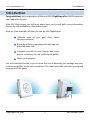
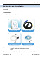
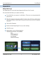
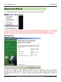
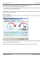
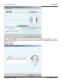
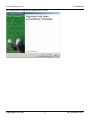
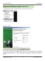
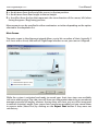
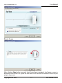
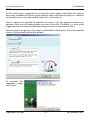
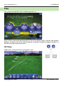
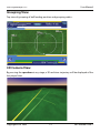
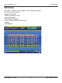
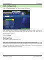
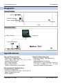
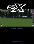
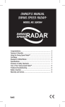
PRO
Golf Club Comparison
and
Calibration System
User Manual
COPYRIGHT NOTICE: The information presented in this document may not be
reproduced without the prior written consent of EDH. EDH retains all rights to the
information in this document. No proprietary, copyright, or other proprietary rights
legends or markings may be removed from any part of this document.
E62-MR400 Issue 2
EDH FlightScope™PRO
User Manual
Introduction
Congratulations on your purchase of the new EDH FlightScope Pro Golf Comparison
and Calibration System.
With EDH FlightScope, you will learn about how you hit golf balls, using information
previously only available to a few professionals.
Here are a few examples of what you can do with FlightScope:
1 Calibrate each of your golf clubs, under
varying conditions.
2 Know the distance, grouping, and shot type you
play with each club.
3 Compare yourself to your friends and other
players including the top professional golfers.
4 Watch your progress.
You will therefore be able to go out onto the course knowing your yardage and shot
making capabilities, under most conditions. This leads inevitably to better scoring and
enjoyment of the game.
Copyright EDH 2005
2
E62-MR400 Issue 2
EDH FlightScope™PRO
User Manual
Getting Started - Installation
Before FlightScope can be used, the Sensor and other hardware and software need to
be installed.
Components
Your FlightScope system comprises several items that require installation.
The components to be installed are:
Optional items: Sensor protective cover,
Notebook Computer, with operating system
Printer
The Computer connects to the Sensor by means of the communications cable.
Copyright EDH 2005
3
E62-MR400 Issue 2
EDH FlightScope™PRO
User Manual
Equipment Installation
The installation is a very important step to achieve the best results from your FlightScope
system, and is best carried out by a qualified FlightScope installer.
Installation requirements and procedures are described in the FlightScope Pro Installation Manual (E62-GP054 Issue 1).
Installing the Flightscope Pro Software
Prerequisites for the Software Installation
1 Laptop, notebook, or desktop Computer with:
- Pentium 3 or later processor or equivalent
- 256 Mbyte memory
- CD ROM drive
- Microsoft Windows 2000, XP Home, or XP Pro
2 FlightScope Pro installation software on CD.
Software Installation Procedure
1 Switch Computer on and wait for operating system to startup.
2 Insert Flightscope CD into CD ROM drive.
automatically.
The installation software will start
3 Follow the steps and instructions provided by the installation software. Accept
the “default” option if unsure about any selection.
4 Once the installation is complete, remove the CD from the Computer and store
in a safe place.
5 If the default options were selected, the FlightScope Pro software will be
available as an Icon on the Computer’s Windows Desktop.
Copyright EDH 2005
4
E62-MR400 Issue 2
EDH FlightScope™PRO
User Manual
Operation
Daily Start-up
The FlightScope Pro system has been designed with “ease of use” in mind.
Also remember that help is just a phone call away.
1 Ensure that the sensor power is switched on. (The sensor can stay permanently
powered on)
2 Place the Computer in a location within 4-5 metres from the Sensor and connect
the Communications Cable (9 pin D connector) to the Sensor and the Computer
com: port.
3 Start up the Computer
4 Double click the FlightScope Pro icon on the desktop.
5 Click OK to start.
6 Wait for Main screen of FlightScope Pro:
The following selections are available:
- Play
- Club Comparison
- Club Calibration
- User Manual
- Advanced Settings
Copyright EDH 2005
5
E62-MR400 Issue 2
EDH FlightScope™PRO
User Manual
Alignment Wizard
The alignment wizard is available from the Sensor Advanced menu.
The Latest FlightScope sensors have a slightly different setup procedure compared
to older versions. The FlightScope software will automaticaly detect your sensor and
display the appropriate setup procedure. Both are described in the following pages.
NEW VERSION
Welcome Screen
On the first screen of the alignment wizard you can initialize your tee position
relative to the radar and set your sensor tilt. The tilt value should never need to
be adjusted, but the tee X, Y and Z value can be changed to match your setup as
follows:
Copyright EDH 2005
6
E62-MR400 Issue 2
EDH FlightScope™PRO
User Manual
X is the distance from the front of the sensor to the tee position.
Y is the distance from floor height to the tee height.
Z is the offset from the line that represents the view direction of the sensor, left (when
facing the green / flag) being positive.
Measurements can be specified in either centimeters or inches depending on the option
selected in the dropdown list.
Tilt / Level Screen
(If you do not see this screen then you have an older sensor. Please turn to p10 which describes the alignment
procedure for older sensors.)
The Tilt angle of the sensor needs to be adjusted to fall within the recommended range
as is optimal for the selected club type.
The Roll angle of the sensor should be adjusted to be as close to zero as possible.
Copyright EDH 2005
7
E62-MR400 Issue 2
EDH FlightScope™PRO
User Manual
After clicking Next when enough shots have been recorded, the Rotate screen is
displayed. Instructions are given on how the sensor should be rotated if necessary for
proper alignment.
Rotate Screen
Copyright EDH 2005
8
E62-MR400 Issue 2
EDH FlightScope™PRO
User Manual
To complete the alignment simply click “Finish”.
Copyright EDH 2005
9
E62-MR400 Issue 2
EDH FlightScope™PRO
User Manual
Alignment Wizard (older sensors)
The alignment wizard is available from the Sensor Advanced menu.
Welcome Screen
On the first screen of the alignment wizard you can initialize your tee position
relative to the radar and set your sensor tilt. The tilt value should never need to
be adjusted, but the tee X, Y and Z value can be changed to match your setup as
follows:
Copyright EDH 2005
10
E62-MR400 Issue 2
EDH FlightScope™PRO
User Manual
X is the distance from the front of the sensor to the tee position.
Y is the distance from floor height to the tee height.
Z is the offset from the line that represents the view direction of the sensor, left (when
facing the green / flag) being positive.
Measurements can be specified in either centimeters or inches depending on the option
selected in the dropdown list.
Main Screen
The main screen in the alignment wizard allows you to hit a number of shots (typically 3
to 5 shots with a 6 iron) that will tell FlightScope whether or not your sensor is aligned.
While the system is activated and ready to record your shots, two views are available:
side view and top view. The side view will show you information about the assumed and
average measured tilt angles, whereas the top view will show you any offset measured
in azimuth (rotation) angle. Once some shots have been recorded, you can cancel them
in reverse order (latest first) by clicking on the Reject Shot button if they were not
satisfactory.
Copyright EDH 2005
11
E62-MR400 Issue 2
EDH FlightScope™PRO
User Manual
Rotate Screen
After clicking Next when enough shots have been recorded, the Rotate screen is
displayed. Instructions are given on how the sensor should be rotated if necessary for
proper alignment.
Copyright EDH 2005
12
E62-MR400 Issue 2
EDH FlightScope™PRO
User Manual
Tilt Screen
The Tilt screen gives suggestions as to how the sensor needs to be tilted. Two options
are usually available: the sensor can be tilted to match what the tilt angle it is currently
assumed to be at or it can be notified what tilt it is physically at.
There is, however, an optimal tilt angle for the sensor and the quality of analysis can
decrease if the true tilt angle deviates too much from this. Therefore it is most often
suggested that the sensor be tilted physically in order to correct any tilt offset.
The two options are given as two choices selectable by check boxes. The recommended
choice is automatically selected by default.
To complete the
alignment simply
click “Finish”.
Copyright EDH 2005
13
E62-MR400 Issue 2
EDH FlightScope™PRO
User Manual
Play
The system may be left in this mode for general use.
Shots will be measured and displayed as they are played. Various tabular and graphic
displays of shot results 3D can be viewed by using the clickable navigation buttons or
the left and right keyboard buttons.
3D View
Flight paths in three-dimensional graphic view:
Copyright EDH 2005
14
or
E62-MR400 Issue 2
EDH FlightScope™PRO
User Manual
Grouping View
Top view of grouping of ball landing position and grouping radius:
3D Camera View
By pressing the spacebar at any stage, a 3D real-time trajectory will be displayed of the
last played shot.
Copyright EDH 2005
15
E62-MR400 Issue 2
EDH FlightScope™PRO
User Manual
Table View
The table contents are arranged in the following groups:
• Distance: Carry & Lateral
• Speed: Club & Ball
• Efficiency: Smash & COR
• Spin: Back & Side
• Time: Tracked & Flight
• Launch Angle: Vertical & Horizontal
• Height
• Classification.
Copyright EDH 2005
16
E62-MR400 Issue 2
EDH FlightScope™PRO
User Manual
Club Comparison
Click on Club Comparison. The following screen will appear:
Enter Surname and first names of client/player. (This will be used as a key for
future data retrieval). Enter brands/shaft types/lofts of clubs to be fitted in the
section provided “Clubs 1-5”.
Click on Continue
Playing Shots
The system is now ready to record shots.
HINT: Check that club displayed at the top corresponds with the club played.
Each shot’s results will be displayed in the Table on the screen. Each shot can either be
accepted (included) or rejected (excluded).
Copyright EDH 2005
17
E62-MR400 Issue 2
EDH FlightScope™PRO
User Manual
Accepted shot data will be saved to Computer file. As many
shots can be played as wished per club.
Select following club or scroll between clubs using
Next Club.
Copyright EDH 2005
18
E62-MR400 Issue 2
EDH FlightScope™PRO
User Manual
The “Results” screen can be viewed at any time by clicking on View all results.
On the “Results” page you can rate your clubs according to various criteria and print all
your results.
Click Resume to return to Comparison.
As with the “Play” module, you can scroll between shot data, shot grouping, 3d, 3d camera,
tracking info and club analysis screens simply by using the clickable navigation buttons
or the left and right keyboard buttons.
The“ Tracking Info”screen
will display a graphical
view of the shot flight
profile.
Copyright EDH 2005
19
E62-MR400 Issue 2
EDH FlightScope™PRO
User Manual
New to version 4 is the “Club Analysis” and “Ball Trajectory” screens.
For Club Analysis, two views are presented:
(a) Clubhead Speed Profile and
(b) Clubhead Acceleration Profile.
Rotational Rate:
By measuring the club head speed, not only as an average speed prior to impact, but
as a high definition speed profile through impact, it is now possible to determine the
effective rotational rate created by a player about 2/1000’s of a second prior to impact.
Correct shaft fitting is now easier than ever before.
Copyright EDH 2005
20
E62-MR400 Issue 2
EDH FlightScope™PRO
User Manual
For Ball Trajectory, two views are presented:
(a) Complete trajectory and
(b) Post Impact.
Roll indicates the the post impact area of the ball or the entire
trajectory of a single result or set of results.
Copyright EDH 2005
21
E62-MR400 Issue 2
EDH FlightScope™PRO
User Manual
Club Calibration
Click Club Calibration on the Main screen.
The following screen will appear:
Enter Surname and first names of client/player. (This will be used as a key for future data
retrieval with Load info).
Enter various clubs to be measured in the section provided. Up to 10 clubs may be
entered.
Click Continue to proceed.
Playing Shots
The system is now ready to record shots.
HINT: Check that club displayed at the top corresponds with the club played.
Each shot’s results will be displayed in the Table on the screen.
Copyright EDH 2005
22
E62-MR400 Issue 2
EDH FlightScope™PRO
User Manual
Each shot can either be accepted (included) or rejected (excluded).
Accepted shot data is saved to computer file. As many shots can be played as wished.
“Club Calibration” functions the same as “Club Comparison”. You can scroll between shot
data, shot grouping, 3d, 3d camera and tracking info screens simply by using the clickable
navigation buttons or the left and right keyboard buttons.
Select Next Club to proceed to the next club or to scroll between clubs.
Copyright EDH 2005
23
E62-MR400 Issue 2
EDH FlightScope™PRO
User Manual
The “Results” screen can be viewed at any time by clicking on View all results.
On the “Results” page you can rate your clubs according to various criteria and print all
your results.
Click Resume to return to Calibration.
Copyright EDH 2005
24
E62-MR400 Issue 2
EDH FlightScope™PRO
User Manual
Printing a report
A report can be printed from any session. Historical sessions that have been saved can
also be recalled and printed.
Reports can be printed from the “Results” screen of FlightScope Pro, or after a Load info
has been performed on saved data.
To print, proceed as follows:
1 Ensure that your printer is connected to the Computer,
is switched on, and has sufficient paper for printing.
2 Check that the data on the screen represents the data
you wish to print (player name, date, etc.)
3 Click on the Printer icon.
4 Select “Trajectory” or “Table” printing from the popup*
5 Wait for the printer to complete printing.
6 Continue
Example of Printed Report
Copyright EDH 2005
25
E62-MR400 Issue 2
EDH FlightScope™PRO
User Manual
Advanced Settings
The Advanced Settings button on the Main screen allows the setting of the measurement
units as either Imperial or Metric standard. This menu can also be shown at any time by
pressing the F10 key.
Com Number
The COM number of the serial port on which
the tracking sensor is connected can be
adjusted by selecting the appropriate port
from the Com Number submenu of the
Sensor advanced menu.
Units
Club units may be set independent from all
the other parameters as golfers often prefer
to measure clubhead speed in miles per
hour while other measurements may be in
metric format.
Altitude
Altitude may be adjusted according to the
height above sea level. At locations higher
than 1000m (3281ft) above sea level the high
altitude option is recommended. Depending
on the type of tracking sensor used, this
setting may or may not be adjustable.
Copyright EDH 2005
26
E62-MR400 Issue 2
EDH FlightScope™PRO
User Manual
System Info
The System Info submenu feature, available in the Sensor advanced menu, gives technical
information about the tracking sensor and software.
Tracking Parameters
Some of the technical parameters used
in the tracking process can be adjusted
in the Sensor Parameters window,
accessible from the Sensor Parameters
item in the Sensor advanced menu.
These parameters should never be
modified unless specifically instructed
by EDH Sport technical support.
Copyright EDH 2005
27
E62-MR400 Issue 2
EDH FlightScope™PRO
User Manual
Raw Data Download
Raw tracking samples can be downloaded from the sensor and saved for advanced
technical diagnostics. Not required during normal use.
Copyright EDH 2005
28
E62-MR400 Issue 2
EDH FlightScope™PRO
User Manual
Sensor Status
The diagnostic status of Sensor is displayed in the upper right hand corner of the Main
screen:
The Connected indicator shows the status of the data
communications connection between the Computer and the
Sensor. This indicator should be constantly “green”.
The Active indicator shows when the Sensor is measuring. The
software controls the Sensor measurement, so that this status
will change during operation and use.
User Manual
To access, click the User Manual button on the Main Screen menu.
Definition of Measured Parameters
Carry Distance : Distance in a straight line from the tee-off spot to where the golf ball
touches the ground again. Roll excluded.
Clubhead Speed : The club speed at the point of impact.
Ball Speed : Speed of the golf ball at the start of flight, in the direction of flight.
Smash : This is a factor of shot efficiency. It provides a very good idea of how sweetly the
ball was struck. Even on perfect shots, the Smash depends on factors such as balls used,
coefficient of restitution of the club, and loft.
HINT: The process allows the fitter to wait for acknowledgment from the client on a
good shot on a specific club, before proceeding and accepting following shots that
have the same or better Smash results (higher value). When changing to the next club,
the process is repeated.
Azimuth : Azimuth angle is the angle, in the horizontal plane, at which the ball travels
from the tee point. Positive angles are to the right (clockwise) and negative angles are
to the left (counter-clockwise).
Launch Angle : The launch angle is the angle at which the ball travels from the tee-off
point from the horizontal plane.
Height : The maximum height that the ball reaches in its flight path.
Classification : The classification of the shot is made based on the measured trajectory
direction and curvature of the flight path.
Copyright EDH 2005
29
E62-MR400 Issue 2
EDH FlightScope™PRO
User Manual
Diagrams
Sensor Position
FlightScope Sensor
Communications
Mains Power
Tee
9’10”
Interconnections
Mains Power
Computer
Communications
Cable
FlightScope™ Sensor
Tee
Mains Power
Specifications
Physical Characteristics
- Dimensions (approximate)
- 330 x 460 x 305 mm (13 x 7 x 12 in)
HeightxWidthxDepth
- Mass (approximate)
- Sensor 3 kg (6.6 lbs)
- Cables & Accessories 3 kg (6.6lbs)
Electrical Characteristics
- Electrical Supply: 100-260 Volt AC
@ 0.5 Amp
- Communications Interface:
RS422/RS232 serial interface, at up to
115 kbps Certified to FCC, CE and
Industry Canada requirements.
Environmental Characteristics
- Ambient Temperature
- Operates between 0 to 40 °C (32 to 104 °F)
- Ingress Protection Level
- IP54 / NEMA-4.
Copyright EDH 2005
30
E62-MR400 Issue 2
EDH FlightScope™PRO
User Manual
Appendix
Electrical Power Requirements
The owner of the equipment is responsible for providing the appropriate mains electrical
power supply for the installation of FlightScope.
Positions
Mains electrical power supply need to be provided at the following points:
a.Sensor mounting position
b.Computer position
Voltage
The supply shall be 95-264 Vac, 50/60 Hz.
Current
The maximum current requirement at each point is 5 A.
Circuit Breaker
The Sensor power point and the Computer power point must be fed via a circuit
breaker.
Sensor Power Outlet/Connection
The sensor power point may be either a standard outlet socket or a screw terminal
connector block in an approved junction box.
If permanently installed in an unprotected outdoors location, the power installation
must have an acceptable health and safety rating for exposed environments (BS7671 or
equivalent).
The outlet should be switched.
Earthing
In all cases, an earth connection shall be provided in addition to the live and neutral
circuits.
Qualified Contractors and Materials
All electrical cabling shall be installed by qualified electrical contractors using methods
and materials that satisfy local safety and regulatory standards.
Copyright EDH 2005
31
E62-MR400 Issue 2
EDH FlightScope™PRO
User Manual
Index
Symbols
3D
10
A
Active
Advanced Settings
Azimuth
24
5, 21
7
B
Ball Speed
Ball Trajectory
7
21
C
Carry Distance
CD
CE
Classification
Clubhead
Clubs
Club Analysis
Club Calibration
Club Comparison
Communications Interface
Computer
Connected
Continue
Current
24
24
24
24
24
2, 13, 14, 17
16
5, 13, 17, 24
1, 5, 18
25
3, 4, 14, 20, 24, 26
20
13, 17, 20
26
D
Dimensions
Distance
25
2, 7
E
Earthing
Electrical Power
Electrical Supply
26
26
25
F
FCC
Flightscope Pro Software
25
4
Copyright EDH 2005
32
E62-MR400 Issue 2
EDH FlightScope™PRO
User Manual
Flight path
24
Sensor Status
Software Installation
Specifications
G
Graphic displays
Grouping
T
10
2, 11, 15, 18
Temperature
Tracking Info
H
Height
Units
21
V
5, 20
21
3, 4, 26
4
25
View all results
Voltage
15, 19
26
W
Windows
K
Keyboard
25
15
U
24
I
Icon
Imperial
Installation
Installation Manual
Interconnections
24
4
25
4
10, 15, 18
L
Launch Angle
Load info
24
17, 20
M
Mass
Metric
25
21
N
Navigation
Next Club
10, 15, 18
14, 18
P
Play
Printer
Printing
10
3, 20
20
R
Resume
15, 19
S
Sensor mounting position
Sensor Position
Sensor power
Copyright EDH 2005
26
25
26
33
E62-MR400 Issue 2