1
Gas Analyzer 810-830
Operating manual
Gas Analyzer 810-830 __
Operating Manual
(ENGLISH)
Rev. 1.3
Manual 810-830
All rights reserved. No part of this user's manual can be reproduced or
transmitted by any electronic or mechanical means, including photocopies,
recording or any other storage and tracing systems for purposes other than the
purchaser's personal use without the Manufacturer's prior written authorisation.
The Manufacturer is not liable for the consequences resulting from user's
misuse of the equipment.
The data and information contained in this manual can be subject to change or
update without prior notice by the Manufacturer.
3
Manual 810-830
CONTENTS
1
Foreword _________________________________________________7
2
Package Contents__________________________________________8
3
WARRANTY _______________________________________________9
4
5
6
7
3.1
Warranty Scope _________________________________________9
3.2
Warranty Period _________________________________________9
3.3
Warranty Application______________________________________9
3.4
Material Return _________________________________________10
3.5
Exclusions and Limitations ________________________________10
Tester Description ________________________________________11
4.1
Reference Standards ____________________________________11
4.2
Main Elements _________________________________________12
Product Installation _______________________________________13
5.1
Power Supply __________________________________________13
5.2
Connect Heat Probe and Rpm Detector ______________________13
5.3
PC Connection _________________________________________13
5.4
Gas Probe Connection ___________________________________14
5.5
Identification Label ______________________________________15
5.6
Technical Specifications __________________________________17
GENERAL INSTRUCTIONS _________________________________18
6.1
Operating Principle ______________________________________18
6.2
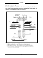
Microbench Principle System ______________________________20
6.3
Intake Circuit Diagram ___________________________________20
6.4
Gas Inlet ______________________________________________21
6.5
Gas Inlet Management Diagram____________________________21
MAINTENANCE SERVICE___________________________________22
7.1
Cleaning ______________________________________________23
7.2
Daily Maintenance. ______________________________________23
7.3
Weekly Maintenance ____________________________________23
7.4
Six-Month Maintenance __________________________________23
7.5
Filtering System Cleaning_________________________________24
4
Manual 810-830
7.6
CONDENSATE FILTER CLEANING ________________________25
7.7
CHANGING GAS FILTER ________________________________25
7.8
CHANGING ACTIVATED CARBON FILTER __________________25
7.9
Checking and Cleaning the Inductive clamps__________________26
7.10
8
CHANGING OXYGEN SENSOR__________________________26
Using the Instrument ______________________________________28
8.1
Switching ON/OFF ______________________________________28
8.2
Using the Keys _________________________________________28
8.3
Commissioning upon First Start-Up _________________________28
8.4 Analyser Configuration ___________________________________28
8.4.1 Selecting the Rev Counter ____________________________ 29
8.4.2 Time and Date Set-up _______________________________ 29
8.4.3 Workshop Data Set-up _______________________________ 30
8.4.4 Standby Time Set Up ________________________________ 30
8.5 Service _______________________________________________30
8.5.1 Gas Analyser Parameters and Data Check _______________ 30
8.5.2 Rev Counter Data Entry and Check _____________________ 31
8.6 Using the Analyser for Gas Analysis ________________________32
8.6.1 Operations to be carried out upon Tester Start-Up__________ 32
8.6.2 Checks and Main Functions of the Exhaust Gas Analyser____ 32
8.6.3 Warm Up _________________________________________ 33
8.6.4 Cell Reset _________________________________________ 33
8.6.5 Residual HC Check _________________________________ 33
8.6.6 Leak Test _________________________________________ 33
8.7 Gas Free Page _________________________________________34
8.7.1 Autozero __________________________________________ 34
8.7.2 Fuel Selection______________________________________ 35
8.7.3 Rpm Division ______________________________________ 35
8.7.4 HC Test __________________________________________ 35
8.7.5 Seal Test _________________________________________ 35
8.7.6 Oil Temperature / NO Displaying Selection_______________ 36
8.7.7 Print of Gas Free Page_______________________________ 36
8.8 Mandatory Emission Test and Gas Official Procedure in Stand Alone
Mode _____________________________________________________36
8.8.1 Preliminary Steps ___________________________________ 36
8.8.2 Vehicle Engine Type Definition_________________________ 36
8.8.3 Test Execution _____________________________________ 38
8.8.4 Report Printout _____________________________________ 40
5
Manual 810-830
9
Software Exhaust analysis system ___________________________41
9.1
Installation_____________________________________________41
9.2
Uninstall Exhaust Analysis System__________________________43
9.3
Configuration __________________________________________44
9.4
Official Test____________________________________________48
9.5
Free page _____________________________________________51
10
Lambda Equations used in the Gas Analyzer _________________52
6
1 Foreword
Dear Customer,
Thank you for having given us your preference in selecting our product. We
think it can bring you the utmost satisfaction during use. For correct use,
please carefully read the instructions included in this user's manual, store it
with care and consult it whenever necessary.
The system is based on the concept of modularity, it can thus be customised
and drawn on user's real needs.
Our exhaust gas analysers are specially suitable for the most demanding
users as for performance and versatility of vehicles emissions analysis.
Thanks to the appealing line characterising the whole range, our products are
the new reference point for the analysis of pollutant emission. All testers are
manufactured in compliance with the most selective quality criteria.
This manual describes the gas analyser 810 used for the polluting emissions
of gasoline vehicles.
This manual describes the use of the device inside a workshop for the
certified check-up ("Blue Tag" for the Italian regulations) and in a MCTC-NET
testing line.
53
810-830
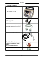
2 Package Contents
Gas analyser 810-830
220V supply cable.
Serial cable for connection to the PC.
Exhaust gas sampling probe.
CD with the “Exhaust Analysis
System” software and the Router
software,
with relevant user’s manuals.
Instrument logbook.
8
810-830
3 WARRANTY
Warranty terms and conditions are defined as follows, unless otherwise
specified in the order confirmation:
3.1 Warranty Scope
TECNOMOTOR ensures the good quality and construction of its
machines; it undertakes, during the warranty specified period, to repair or
replace for free the parts whose failure or early wear are due to bad
quality of the used materials, manufacturing faults or defective
assembling.
The warranty does not cover those parts whose failure or wear are
due to:
- Failure to comply with the instructions contained in the Use and
Maintenance Manual.
- No maintenance service or incorrect maintenance.
- User negligence in checking levels, filter cleaning, auxiliary services,
and power supply.
- The use of unsuitable tools for ordinary and extraordinary
maintenance.
- Changes and/or tampering carried out by the user or third parties
without previous approval of TECNOMOTOR.
- The use of non-original spare parts.
3.2 Warranty Period
The warranty period is 12 MONTHS beginning from the delivery date.
This term is definitive and is not subject to extensions even in case of
replacements or repairs during such period.
3.3 Warranty Application
To determine the causes and apply the warranty, it is necessary to send
the parts you want to be replaced under warranty to TECNOMOTOR or
to authorised service centres.
9
810-830
TECNOMOTOR will decide whether to carry out repairs or replacements
under warranty in-house, by third parties, or on site.
As far as the on site services are concerned, the customer shall provide
the power supply, the extraordinary equipment, the auxiliary personnel,
as well as bear the costs for travel, board and lodging of the
TECNOMOTOR staff.
3.4 Material Return
Before sending to TECNOMOTOR the parts you request to be replaced
or repaired under warranty, it is necessary to transmit all information to
the Service Department for its approval. All parts shall be suitably
packed in order to avoid any damage due to the transport, and shall be
supplied with a document specifying:
- machine serial number;
- part number;
- detailed description of the fault and how it occurred.
The parts under warranty are delivered ex-works; the replaced parts will
be of TECNOMOTOR property and shall be returned ex-works.
3.5 Exclusions and Limitations
- The warranty does not cover materials and parts subject to
normal wear such as connection cables, parts and accessories
outside the device, etc.
10
810-830
4 Tester Description
Tester 810 is an analyser used to measure the quantity of pollutants inside
vehicles exhaust gases.
To measure carbon monoxide (CO), carbon dioxide (CO2) and unburned
hydrocarbons (HC) concentration, a reading cell applying the NDIR (Non
Dispersive Infra Red) technology is used. Oxygen (O2) and nitrogen oxide
(optional) are measured by means of electrochemical cells.
Gas analyser mod.810 features the following functions:
• Vehicles exhaust gas analysis
• Engine rpm reading.
• Engine oil temperature reading
Test reports can be printed out on a coupon thanks via a printer positioned on
instrument control panel.
If you wish to use instrument on an MCTCNET testing line, refer to the
section relating to PC side software set-up.
Tester can be equipped with a battery-operated serial rev counter allowing to
detect engine rpm by connecting sensor to vehicle battery.
4.1 Reference Standards
The analyser has been manufactured to comply with the Ministerial Decree
628 dtd 23rd October 1996 and circular letter 88/95 dtd 6th September 1999,
as well as with the circular letter prot. No. 6247/698/99 dtd 16/11/99, and
following changes and integration.
It has been manufactured also in compliance with the provisions of OIML
R99, Edition 2000 (Class 0), and ISO 3930 edition 2000 International
Standard.
Gas analyser 810 can be integrated in a M.C.T.C.NET testing line.
11
810-830
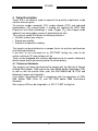
4.2 Main Elements
Gas analyser is equipped with an alphanumeric display, with 4 lines having
20 digits each. An alphanumeric keypad and special function keys allow the
operator to move quickly among the different menus offered by the tester.
Function key used to
enable the numerical
writing, capital letters or
small letters modes.
Arrow keys to move
in the menus
Alphanumeric keys to
enter data
4-line x 20-column
display for test data
displaying.
24-column thermal printer
for test reports printout
12
810-830
5 Product Installation
At first, remove analyser from package, and connect the supplied power
cable to the gas analyser.
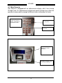
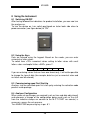
5.1 Power Supply
The device shall be powered through the power cable supplied with the
package.
Insert the supply cable in the outlet placed in the tester rear side, as shown in
the picture below.
5.2 Connect Heat Probe and Rpm Detector
Special inputs for probes connection
are located on tester back side.
In particular, the cup connector
marked with “°C” will have to be used
to connect heat probe, while
connector marked with “RPM” will
have to be used to connect inductive
clamps rev counter.
5.3 PC Connection
13
810-830
A special 9-pole cup socket marked
with the PC symbol is positioned on
tester back side. This is the
connector to be used to connect and
communicate with PC. Connect the
serial cable coming with the tester to
this input.
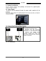
5.4 Gas Probe Connection
The gas probe features a metallic
nozzle collecting the gases, and shall
be inserted in the vehicle exhaust
pipe, whereas the other side shall be
connected to the analyser.
14
810-830
The instrument gas inlet is situated
on the condensate separator.
Connect the gas sampling probe as
shown in picture.
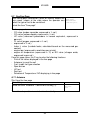
5.5 Identification Label
The identification label on the analysis module contains data relevant to year
of production, serial number, approval number, besides manufacturer name
and instrument model.
It also provides specific technical data of the measurement system, as
required by the Standards in force.
15
810-830
A copy of the instrument original identification label shall be applied in the
space below. The user shall always refer to the identification data on this
label every time he/she needs information.
COPY OF THE
IDENTIFICATION LABEL
OF GAS ANALYSER 810
The label placed on the analyser rear side.
16
810-830
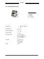
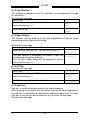
5.6 Technical Specifications
Tester dimensions:
h
H = 33 cm
L = 34 cm
W = 22.5 cm
w
l
Power supply
•
•
220/110V -50/60 Hz.
12V
Absorbed power
30 W at 12 V
Operating temperature
5°C....40°C
Relative humidity
0 .... 95 %
Measurement fields
CO = 0 - 9.99 % vol.
C02 = 0 - 1 9 . 9 % vol.
HC = 0- 10,000 ppm vol.
02 = 0 - 25 % vol.
Resolution
CO - 0.01 % vol.
C0 2 -0.1 % vol.
HC - 1 ppm vol.
O2 - 0.01 % vol.
6.2 Kg
Weight
17
810-830
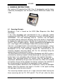
6 GENERAL INSTRUCTIONS
Gas analyser 810 acquired the OIML Class 0 homologation and the Italian
Conformity Homologation with Ministerial Decree 628/96 dtd October 23rd
1996.
6.1 Operating Principle
Microbench II cell is based on the NDIR (Non Dispersive Infra Red)
technology.
It has been developed and manufactured to be a small-size module
complying with OIML R99 Class 0 requirements and with ISO3930 technical
specifications. The new technology used to minimise size and power
consumption did not reduce cell efficiency, but on the contrary it increased it
by allowing the reading of 5 gases. Besides the 3 common gases (CO, CO2
and HC), thanks to special sensors – directly connected and managed by the
cell – also Oxygen (O2) and Nitrogen Oxides (NOx) can be analysed.
Cell size is so compact thanks to the elimination of all moving parts, such as
all those mechanical systems used so far to interrupt the infrared beam. The
development of this new technology allowed the manufacturing of an
extremely compact measuring bench with the first advantage being the
reduced sensitivity to mechanical shocks.
The measurement of the gases analysed by Microbench with NDIR system is
carried out by selecting a special infrared wavelength for each gas where it is
known there is max. absorption and no other gas has important absorption.
Special filters positioned before the receiver allow the passage of the
wavelengths absorbed by the gas to be measured, only. When the sampling
cell contains the gas to be sampled, the receiver measures the reduction of
the infrared energy transmitted for the wavelength of each single gas.
The electronic process determines the i/i0 difference, namely the absorption
degree, where the reference start signal is i0, while i is the signal resulting
after passage inside the measuring cell.
The measuring chamber consists of a single aluminium block housing the
three measuring cells for CO, CO2 and HC. The HC cell, unlike the other
18
810-830
ones, also contains a reference cell to make HC reading more consistent, and
to give a greater accuracy level to the whole block.
19
810-830
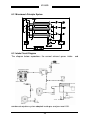
6.2 Microbench Principle System
6.3 Intake Circuit Diagram
The diagram below reproduces the correct exhaust gases intake
condensate ejection system adopted inside gas analyser mod. 810.
20
and
810-830
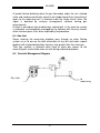
A special device detecting when the gas flow drops under the min. allowed
value and sending and electric signal to the feeder board then transmitting it
again to the measuring cell is inserted inside the intake circuit. Here, the
signal is detected by analyser management software locking gas
measurement.
A check is carried out also to detect any sealing fault. In this case the system
is automatic, and completely managed by the software with the only manual
action to close gases inlet, when required by the procedure.
6.4 Gas Inlet
Gases entering the measuring chamber pass through an outer filtering
system so as to ensure the total elimination of any dirt and water vapour
together with suspended particles having a size greater than 4um from gas.
Then gas reaches a solenoid valve used to close gas access to the
measuring cell, and to allow room air inlet during autozero procedure.
6.5 Gas Inlet Management Diagram
Gas inlet
to
measuring
21
810-830
7 MAINTENANCE SERVICE
This chapter contains all information necessary to keep your device in perfect
conditions.
To carry out an excellent maintenance service, it is essential to carefully read
and, in case of need, consult this manual section. This will ensure a correct
maintenance service and, consequently, a device trouble-free operation and
a longer life.
WARNING: Before carrying out any maintenance operation,
make sure that the power supply is off. Wait for the power
to be off before touching any electric part.
WARNING: Staff unaware of the instructions herein (that
shall nevertheless be spread as widely as possible) shall
not be allowed to use, work on internal parts of the tester
and to carry out maintenance services.
WARNING: Do not use tools or other material that are not
suitable for repairs.
Upon each reading completion:
1) Carry out a quick visual check of filtering system so as to exclude any
accidental or unexpected damage. For a more detailed periodical check,
refer to “Filtering System Cleaning” under the “Maintenance” section of this
manual.
2) Make sure that no exhaust gases are left inside the tester, by making this
latter operate in free reading page mode with the probe outside the exhaust
pipe.
3) At the end of each working day, disconnect probe from inlet filter (fabrics
filter) and use a jet of compressed air to blow inside the black pipe on filter
insertion side so as to eliminate any condensate or soot deposited inside
the sampling probe pipe
22
810-830
7.1 Cleaning
Warning: do not carry out any cleaning operation when the instrument
is working.
Proceed as follows to clean the instrument:
Make sure that the multiple outlet switch is OFF.
Remove dust with a cloth soaked in alcohol.
WARNING: Do not clean the inside part of
the condensate separator chambers with
alcohol.
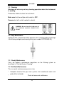
7.2 Daily Maintenance.
Check the filter (see picture below) placed on the sampling probe and change
if the filtering side gets continuously dirty (part number FILTROGAS-01).
7.3 Weekly Maintenance
Carry out ordinary maintenance operations on the filtering system as
described in “Filtering System Cleaning".
7.4 Six-Month Maintenance
This six-month maintenance consists in the:
*
*
Complete check of the gas main system, from condensate drain until
probe (filter included).
Check of accessories wholeness
23
810-830
7.5 Filtering System Cleaning
The filters positioned on tester rear side have a very Important function as
they protect the delicate inner mechanisms from outside foreign bodies and
impurities. Their proper cleaning is thus essential.
Condensate
separator
Gas filtering
body
Cup
body
Cup OR seal
Filter OR seal
OR
conveyor
White
gas
filter
Rubber gasket
Condensate
Red
filter
recognition
stripe
Threaded
bolt
cup
cup
Union
Small filter
Warning:
1) Make sure that the 2 cup OR seals are always present
2) The “white Gas filter” gets dirty from the inside to the outside
3) The “Conveyor”-“condensate filter” assy is pressure-fitted onto
condensate separator body
24
stud
810-830
7.6 CONDENSATE FILTER CLEANING
• Disconnect transparent pipe from union, and change small filter in
case it is blackened.
• Loosen cup anticlockwise taking care that the OR seal does not come
out of the body.
• Slide out the whole condensate filter from below.
• Dip the filter block inside a solution of hot water and detergent (not
solvent-based) for a few minutes, then dry it.
• Clean cup with compressed air (DO NOT USE ALCOHOL) or with a
cloth to dry any condensate residues.
• Refit filter block.
• Screw cup again with the utmost care.
7.7 CHANGING GAS FILTER
Change this part only if the filter has become grey.
• Loosen cup anticlockwise taking care that the OR seal does not come
out of the body.
• Loosen threaded stud bolt by hand or using a 6mm hex. wrench, and
remove Gas filter.
• Fit a new filter, taking care that the two rubber gaskets are always
placed in-between.
7.8 CHANGING ACTIVATED CARBON FILTER
Filter is used to purify air in order to remove any dust or unburned
hydrocarbons (HC) from cell.
Activated carbon filter ( Part No.FILTER-Ø2)
The duration of this filter depends on the air HC content.
Analyser has better to be positioned far from fuel or solvent containers.
Whenever the analyser detects a negative concentration of HC ( - 5 / -10 HC
ppm ) during the HC testing phase, change the activated carbon filter.
Under tester optimal conditions, this filter will have to be changed once a
year.
To change filter, proceed as follows:
• Disconnect pipe between filter and air inlet
• Slide filter out of its seat
• Change filter and connect air outlet pipe
25
810-830
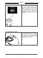
7.9 Checking and Cleaning the Inductive clamps
This operation is very simple:
• Loosen brass adjuster, and open clamps,
• Then clean the two inner ferrite elements so as to allow a perfect
contact with each other.
• During this operation, check if some ferrite parts are damaged. If this
should be the case, do not try to glue the broken pieces as the part
operation would be seriously affected, but ask for the new spare part
RC501-DB.
7.10 CHANGING OXYGEN SENSOR
For tester correct operation, the electrochemical sensor positioned inside
instrument shall be changed whenever the CHANGE OXYGEN SENSOR
message is displayed on the monitor.
Sensor replacement shall be considered as an annual ordinary maintenance
procedure, and will have to be carried out by authorised personnel to prevent
any damage to the instrument.
Technical service centres and Tecnomotor change oxygen sensor both
during periodical checks and in case of any sensor malfunction.
7.11 GAS CALIBRATION
Gas analyzers instruments, need to be periodically calibrated by a
Tecnomotor authorized service center or third parts authorized.
The Gas Calibration procedure is performed using sample gas bottle which
allows at the measurements carried out from the instrument, to respect the
right accuracy requested by the norm.
The interval time for instrument type 810 and 830 for gas calibration is 12
months.
26
810-830
WARNING: Oxygen sensor reaches its max. nominal voltage
approx. 24 hours after having been taken out from its
hermetic package. It is nevertheless enough to remove it
from the package at least 1 hour before installation.
Important: Oxygen sensor has a limited lifetime: it can be compared to a
common electrochemical battery, and it thus features a natural discharge.
The duration is of about 12 - 15 MONTHS FROM TESTER
MANUFACTURING DATE; tester use or inactivity DO NOT VARY sensor
lifetime. Oxygen sensors discharge when they come into contact with
atmospherical oxygen. Spare sensors are supplied inside a plastic package
that does not contain oxygen, so they do not start discharge until they are
removed from such a package.
27
810-830
8 Using the Instrument
8.1 Switching ON/OFF
After having followed the indications for product installation, you can now turn
the analyser on.
To turn the device on, turn switch positioned on tester back side close to
power connector (see figure below) to “ON".
8.2 Using the Keys
Data are entered using the keypad. Based on the needs, you can enter
numerical or letter values.
To switch from <123> numerical values setting to letter values with small
letters <abc> and capital letters <ABC>, press F.
<123>
F
<abc>
F
<abc>
F
<123>
If you are entering values that can have one format only, it will not be possible
to change the type of data (for example, date has just a numerical value and
no letters can be entered).
8.3 Commissioning upon First Start-Up
Analyser shall be activated upon first start-up by entering the activation code
present inside package.
8.4 Analyser Configuration
When some set-up changes are required (such as time and date adjustment)
and whenever a change of the configuration being used (such as the shift
from the inductive clamps rev counter to the M.C.T.C.NET rev counter) is
necessary, access the set-up menu.
Turn ANALYSER on pressing key in par. 8.1.
28
810-830
Upon switching on, a short introduction page followed by the available
functions will be displayed.
To access the set-up menu, press function key (F) while the tester is being
turned on, or press ESC twice when the tester is already in the main menu for
test type selection.
►Set-up
Service
Rev counter
Time and Date
►Workshop data
…
Select the Set-up item and press the key (↵) to confirm.
Select the desired item and press the key (↵) to confirm.
Press ESC to quit the Setup menu.
8.4.1 Selecting the Rev Counter
Press ESC during the starting page.
Select the Set-up item and press the key (↵) to confirm.
Select the Rev Counter item and press the key (↵) to
confirm.
Select the rev counter “Type”. It can be the “Inner” one of
the instrument (for instruments with integrated rev counter),
and outside complying with the MCTC-Net communication
protocol, or outside of the Stand Alone type.
When a Stand Alone rev counter is used, the software
will require to manually enter the reading before the end of
an official testing.
►Set-up
Service
►Rev counter
Time and Date
Workshop data
…
►Inner
MCTC-NET
Stand Alone
8.4.2 Time and Date Set-up
Press ESC during the starting page, or press function key F, or press ESC
twice from tester main menu.
►Set-up
Select the Set-up item and press the key (↵) to confirm.
Service
Select the "Time and Date" item and press the key (↵) to
confirm.
Select the "Time" item and press the confirmation key (↵)
to change the time.
Enter time in the hh mm ss format.
Press (↵) to confirm or ESC to abort the operation.
To edit date, select “Date”, and press (↵) to confirm
29
Rev counter
► Time and Date
Workshop data
…
►Time
Date
Time
16.29.31
hh mm ss
Time
►Date
810-830
Date
30/05/2005
dd mm yyyy
Enter date in the dd mm yyyy format.
Press (↵) to confirm or ESC to abort the operation.
8.4.3 Workshop Data Set-up
Press ESC during the starting page.
Select the Set-up item and press the key (↵) to confirm.
Select the "Workshop data" item and press the key (↵) to
confirm.
Select the workshop relevant items and press the key (↵)
to confirm them.
►Set-up
Service
Rev counter
Time and Date
►Workshop data
…
►Workshop name
Address
City
…
8.4.4 Standby Time Set Up
The standby function is used to protect the most delicate parts of exhaust gas
analyser. When analyser keys are not pressed for a set time, system will
automatically enter the standby mode thus preventing parts useless wear and
reducing consumption levels.
The time, expressed in minutes, after which system enters the standby mode,
is set as follows:
Select the Set-up item and press the key (↵) to confirm. ►Set-up
Service
Select the "Standby Time" item and press the key (↵) to
confirm.
Time and Date
Workshop data
►Standby Time (m)
8.5 Service
These functions are accessed when measuring modules setting has to be
checked. Some functions have to be carried out only by technical service
centres and are password-protected.
8.5.1 Gas Analyser Parameters and Data Check
Press ESC or F during starting page.
Select the Service item and press the key (↵) to confirm.
Select the "Gas Analyser" item and press the key (↵) to
confirm.
Once the “Gas Analyser” menu has been accessed, you
can display and edit the following items:
30
Setup
►Service
►Gas Analyser
Rev counter
…
810-830
-
Make
Model
No. Homologation
Serial No.
Expiration date (to be edited by authorised
technicians, only)
IMPORTANT
Upon first installation, and anyway after any change to
the instruments used for emissions measurement, check
that the stored values match with those inside
metrological logbooks, with special attention to the serial
number.
WARNING!
The parameters of this section are reported in the official
report printouts!
8.5.2 Rev Counter Data Entry and Check
This paragraph describes how to enter non MCTC-Net (inside testers, stand
alone, etc...) rev counters data.
If a MCTC-Net rev counter is connected, the information are directly read by
the device.
Press ESC during the starting page.
Select the Service item and press the key (↵) to confirm.
Select the Rev Counter item and press the key (↵) to
confirm.
Select the type of rev counter to be set:
- Inside Gas: inside gas analyser
- Stand Alone: not connected to gas analyser
(revolutions will be entered by the user)
Here are the parameters for each one of the two rev
counters:
- Make
- Model
- No. Homologation
- Serial
No.
- Expiration date
31
Setup
►Service
Gas Analyser
►Rev counter
…
►Inside Gas
Stand Alone
810-830
WARNING!
The parameters of this section are reported in the official
report printouts!
8.6 Using the Analyser for Gas Analysis
The main available functions for vehicles check are:
- Free Page, to read emissions main values as well as engine main
values (temperature and rpm)
- Certified workshop check-up (blue tag for the Italian regulations) for the
release of the blue tag for gasoline vehicles;
- Official Procedure, for the execution of the test according to the latest
regulations for gas analyses.
To carry out any test with the gas analyser 810, at first you will have to
connect the probes coming with the tester to detect engine rpm and engine oil
temperature, refer to par. 5.2 if no MCTCNET network is available or to par.
5.3 if the MCTCNET testing network is available.
You can now turn the tester on using the special network switch positioned on
the back side.
If the tester has not been set-up yet to operate with the supplied probes, then
follow the procedure described in section 7 before continuing.
8.6.1 Operations to be carried out upon Tester Start-Up
From tester main menu, you can select the type of test you are wishing to
carry out. If some peripheral unit does not respond correctly (the rev counter,
for example) when the desired test is selected, you can decide whether
continuing the reading using the available alternatives (for example, when the
rev counter is concerned, you can use the one inside the tester or the one
inside the vehicle) or interrupting the test.
8.6.2 Checks and Main Functions of the Exhaust Gas Analyser
The program automatically carries out some inspections and operations that
ensure the device correct measurement function, in particular:
- warm up
- cell reset
- residual HC test
- Leak test
32
810-830
8.6.3 Warm Up
The cell warm up phase is useful for the thermal stabilisation of the
measurement part. To continue the test wait for this phase to be completed.
The warm up time depends on the starting cell conditions: the higher the
starting temperature, the lower the warm up time.
8.6.4 Cell Reset
Cell reset function (or autozero) allows calibrating the CO, CO2 and HC
values as well as the environmental value of O2 concentration (close to 20.90
% vol.).
Environmental air passes through an activated carbon filter and is delivered
to the measuring cell. The inlet from the gas sampling probe is disabled
during this phase.
8.6.5 Residual HC Check
HC testing is used to check that no residual unburned hydrocarbons are
present inside the inlet circuit before carrying out a test. The HC value for
cars shall be below 20 ppm vol.
8.6.6 Leak Test
The aim of the seal test is to check the gas sampling circuit sealing capacity,
as the reading would be distorted by any air seepage.
No measurement reading can be carried out if the seal test is not passed with
positive outcome.
IMPORTANT
The Leak test is automatically required by the instrument daily after the warm
up phase and before to start the measurement procedure (Free Page)
Sampling circuit seal test is carried out by generating a vacuum inside the
pneumatic circuit: a displayed message will indicate the point where the user
has to kink the probe.
The analyser, thanks to the pressure sensor, detects the max. vacuum level
reached.
Now pump is switched off, and analyser checks for a few seconds that the
vacuum inside pipe is kept at the max. level.
If the vacuum level decreases during testing, it means that there is a leakage
in the pneumatic system, and the test is failed. If carried out correctly, seal
test has a daily validity.
33
810-830
8.7 Gas Free Page
After having been switched on, tester will directly access the
main menu (shown at the side) where the operator can
select the type of test to be carried out.
Select the item "Free page".
<Gas analysis>
►Free page
Mand.em.test
Official proc.
The free page shows:
- CO value (carbon monoxide, expressed in % vol.)
- CO2 value (carbon dioxide, expressed in % vol.)
- HC value (unburned hydrocarbons in hexane equivalent, expressed in
ppm vol.)
- O2 value (oxygen, expressed in % vol.)
- expressed in % vol.)
- factor λ value (Lambda factor, calculated based on the measured gas
content)
- engine rpm (expressed in revolutions per minute)
- engine oil temperature (expressed in °C) or NO value (nitrogen oxide,
expressed in ppm vol.)
From this page, press the F key to enter the following functions:
- Print of the values displayed in the free page
- Autozero, to reset the cell
- Fuel, to edit fuel type selection
- Rpm division
- HC test
- Seal test
- Selection of Temperature / NO displaying in free page
8.7.1 Autozero
Start from the free page
Press F key.
Select the item "Autozero". Confirm with the key (↵).
The cell reset operation is carried out automatically.
34
Print
►Autozero
Fuel
…
810-830
8.7.2 Fuel Selection
This selection is important as the COc and factor λ values depend on the type
of vehicle fuel.
Start from the free page
Press F key.
Print
Select the item relating to fuel selection.
Autozero
Confirm with the key (↵).
►Fuel
GASOLINE
LPG
►METHANE
Select vehicle fuel.
8.7.3 Rpm Division
This function shall be used to set the rpm multiplication or division factor
according to vehicle type you are testing.
Start from the free page
Press F key.
Select the item "Rpm division". Confirm with the key (↵).
If the rpm counter is connected, the display shows the
calculated rpm using the set divisor.
Press the up or down arrow keys to change the divisor.
Confirm with the key (↵).
8.7.4 HC Test
Start from the free page
Press F key.
Select the item relating to HC Test.
Confirm with the key (↵).
Autozero
Fuel
►Rpm division
Rpm=1020 RPM
Division by: 1
Fuel
Rpm division
►HC Test
The HC test is carried out automatically.
RESIDUAL HC TEST
IN PROGRESS
8.7.5 Seal Test
Seal test is used to check pneumatic circuit sealing capacity.
When carrying out an official test or the Blue Tag (for the Italian regulations),
the seal test is required and automatically performed upon tester first daily
start-up. A seal test can be carried out at any time from the free page.
Start from the free page
35
810-830
Press F key.
Select the item relating to Seal Test.
Confirm with the key (↵).
Rpm division
HC test
►Seal Test
Carry out the Seal Test following the indications displayed
on the tester. User shall simply close the probe, and after
having created a vacuum inside the pneumatic circuit the
tester will turn the pump off to check that the created
vacuum remains within set tolerance limits.
8.7.6 Oil Temperature / NO Displaying Selection
Start from the free page
Press F key.
Select the item relating to engine oil temperature or NO
displaying.
The currently-displayed item is marked with an asterisk.
Press ESC if you wish to keep the displayed item
unchanged.
Press ↵ to change the displayed item.
Seal test
CLOSE PROBE
…
HC test
Seal test
►*Oil / NOx
8.7.7 Print of Gas Free Page
It is possible to print the values displayed in the free page. Start from this
page.
Press F key.
Select the item "Print" and press ↵.
►Print
…
8.8 Mandatory Emission Test and Gas Official Procedure in Stand Alone
Mode
8.8.1 Preliminary Steps
- Make sure that vehicle exhaust pipe is sealed, and that the emissions
control system, if any, features the indispensable outfit.
- Insert the gas sampling probe in the exhaust pipe.
- Define the vehicle nominal values: type of fuel, engine temperature, rpm at
idle speed, emission limits (where indicated).
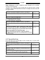
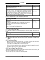
8.8.2 Vehicle Engine Type Definition
To define the type of test to be carried out and the relevant limit values, you
will have to select the “Engine Type” item.
To select the right item, refer to the following table
36
810-830
Engine Type
Category
Limits and notes concerning the engine type.
Test without limit values, “at best” adjustment, test at
idle speed. Applicable to vehicles without OM9439RT1902 homologation.
COc value ≤ 4.5%vol. (at idle speed)
<86 OM9439-RT1902 Applicable to vehicles registered before 01/10/86, but
homologated according to OM9439-RT1902
COc value ≤ 3.5%vol. (at idle speed)
Applicable to non-catalytic vehicles, or vehicles
NO CAT – RETROFIT
featuring a RETROFIT catalytic system and registered
after 01/10/86.
COc value ≤ 0.5%vol. (at idle speed)
COc value ≤ 0.3%vol.; 0.97 ≤ λ ≤ 1.03 (at accelerated
CAT
idle speed)
Applicable to catalytic vehicles, with Lambda sensor.
COc value ≤ 0.3%vol. (at idle speed)
COc value ≤ 0.2%vol.; 0.97 ≤ λ ≤ 1.03 (at accelerated
idle speed)
CAT. > 01-07-2002
Applicable to catalytic vehicles with Lambda sensor
and homologated according to 70/220/EEC, 98/69/CE,
GU L350 limits, or registered after 01/07/2002
<86
This selection is, obviously, very important for the test success. The
Technical Manager shall carefully check the correct definition of the vehicle.
For example, in case of a catalytic vehicle registered in 2001 but
homologated according to 70/220/EEC limits, you will have to select the
“CAT. > 01-07-2002” category instead of the "CAT" one.
37
810-830
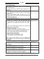
8.8.3 Test Execution
Upon analyser switching on, select the item relating to
the desired function.
Press the arrow keys to select the item and the key (↵)
to confirm it.
After having checked the connection with instruments,
analyser will require to select the type of vehicle engine
(see par. 8.8.2).
Based on the selection made, the type of test to be
carried out and the limit values (that can nevertheless be
edited) to be used are set.
Press the confirmation key (↵).
To display and, if necessary, edit test data (emissions
limits, rpm intervals at idle and accelerated idle speed,
and engine oil min. temperature) select the “Edit Limits”
item.
Free page
Mand.em.test
Official proc.
<Engine Type>
…
►CAT > 01-07-2002
Start test
►Change limits
Environment data
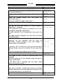
Based on the selected type of vehicle, all or some of the
following values can be edited:
-
Engine oil min. temperature
COc upper limit measured during reading at idle speed
COc upper limit measured during reading at accelerated idle speed
Factor λ lower limit during reading at accelerated idle speed
Factor λ upper limit during reading at accelerated idle speed
Engine rpm lower limit at idle speed
Engine rpm upper limit at idle speed
Engine rpm lower limit at accelerated idle speed
Engine rpm upper limit at accelerated idle speed
These data shall be edited if they are specified on
vehicle logbook. If not, the preset values shall be kept
unchanged.
Select the item "Environment data" to display and
change the values of environment temperature, pressure
and humidity.
If necessary, change the environment temperature.
Press the confirmation key (↵) to continue.
If necessary, change the environment pressure.
Press the confirmation key (↵) to continue.
If necessary, change the environment humidity.
To conclude the environment data change phase, press
38
Start test
Change limits
► Environment data
<123>
Temperature [°C]
20
<123>
Pressure [kPa]
101.2
<123>
Humidity[%]
810-830
the confirmation key (↵).
30
To start the test, select the item “Start Test” and press
the confirmation key (↵).
Select the first vehicle fuel, and press the confirmation
key (↵).
Select the second vehicle fuel, and press the
confirmation key (↵).
In case of single fuel supply, select item “---”.
Select the number of vehicle exhaust pipes.
► Start test
Change limits
Environment data
►GASOLINE
LPG
METHANE
►--LPG
METHANE
After gas cell reset and residual HC check, engine oil
temperature is checked.
If the measured value reaches or exceeds the set limit,
the program proceeds automatically.
To enter manually the oil temperature value, press the
key ↵.
The report printout highlights the data that have been
entered manually.
To check that all values are correct, the main values
necessary for test execution and the main set
parameters (vehicle category, fuels and number of
exhaust pipes) are displayed.
If you press the F function key, you can reset cell again,
edit rpm divider, carry out a residual HC test, and a seal
test.
To start the measurement phase, press the key ↵.
Follow the displayed instructions.
NUMBER
PIPES
1
OF
EXHAUST
Oil T = 76 °C
Min. limit value: 80
°C
COc=0.15 % λ=1.022
RPM= 1020
CAT > 01-07-2002
1. GASOLINE
2. --Number
of
exhaust
pipes 1
↵ Test Start
INSERT PROBE INSIDE
EXHAUST PIPE
Once probe has been inserted, the following steps will be
displayed.
Bring the engine rpm to the indicated range and wait for
the gas stabilisation.
If the "Blue Tag" is selected, you can force values
acquisition by pressing key ↵.
Once test is finished, if engine rpm value has not been
correctly detected, you will be required to manually enter
the measured values as an alternative.
The test result is displayed at the end of it.
39
RESULT
SPEED:
AT
R
IDLE
810-830
Press the key ↵ to go on.
Now you can repeat the reading, force test outcome,
issue a report printout, and go back to main menu.
8.8.4 Report Printout
Select the "Print" item and confirm it with the key ↵.
Enter the vehicle data: make, model, number plate,
frame number, mileage, year of first registration.
Check the name of the Technical Manager who carried
out the test, and change it, if necessary.
40
COc=0.1 % < 0.3 %
RESULT AT MIN ACC:
R
COc=0.1 % < 0.2 %
λ=1.002
0.97-1.03
REPEAT TEST
CHANGE RESULT
PRINT
►END
REPEAT TEST
CHANGE RESULT
►PRINT
END
810-830
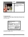
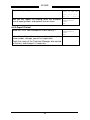
9 Software Exhaust analysis system
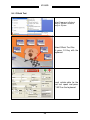
9.1 Installation
Insert The cd of Exhaust
Analysis System in the CD
Drive.
The installation
automatic mode
start
Select Exhaust Analysis
System Multilanguage (the
second option)
41
in
810-830
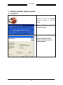
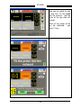
You are now ready to install.
Press next to start.
Insert the key when required
it.
The intstallation key is:
“5123-TME-0174”
42
810-830
Select the next Button and
wait that the installation is
finished.
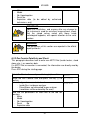
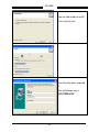
9.2 Uninstall Exhaust Analysis System
If you want uninstall the
exhaust Analysis System
select
Start->Programs->Exhaust
Analysis System->Uninstall
43
810-830
Select the uninstall Method:
Automatic mode is recommended
Press Next and wait the end of the
uninstall process.
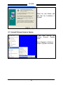
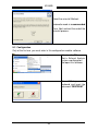
9.3 Configuration
Only at the first use you must enter in this configuration module software.
Select on the PC
Start-> Exhaust Analysis
system->configuration
and open this software.
Press “F1” key on the
keyboard and insert the
password “CENTROAT”
44
810-830
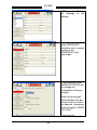
NOW you can Change
the language of the
software
Select WORKSHOP
secondary menu and put
the data of the
WORKSHOP in the
relative box.
In the secondary menu
EMISSION TESTER you
can change the
configuration of the gas
Analyzer.
Select the correct port
Comunication of the gas
analyzer and if you have
the inductive Tachometer
select the option “INSIDE
THE TOOL”
if you have the
45
810-830
temperature PROBE
select the option “INSIDE
THE TOOL”
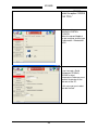
In the secondary menu
EMISSION TESTER>CONFIG
Select the correct Model of
the gas analyzer and the type
of counication : Bluetooth or
rs232.
If you have got a Serial
Tachometer (PFM941)
OR/AND a serial
Temperature Probe you must
connect the devices at the
port com of the PC.
In this case you must select
“outside the tool”.
46
810-830
Select the correct port for the
serial Tachometer and the
MCTCNET type.
If you have a rs232
Tecnomotor
Temperature
Probe:
select the rs232 gas Analyzer
Temperature Probe for the
Gas Analyzer and the correct
port com for the comunication
with the probe.
47
810-830
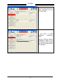
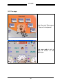
9.4 Official Test
Select Programmi->Exhaust
Analysis System->Exhaust
Analysis System
Select Official Test Gas
Or press F4 Key with the
keyboard.
Insert vehicle data for the
final test report and press
F1 KEY on the keyboard.
48
810-830
Now you are ready to start
a new test. Fit the probe
into the exhaust and the
value of the gas data will
change.
When all the values of the
gas be stabilized
,you
press F1 key.
49
810-830
When the official test is finished
you can print a Report.
50
810-830
9.5 Free page
From the main Menu press
F1 key on the keyboard
Free page mode is only a
page of misure of the
typical gas
51
810-830
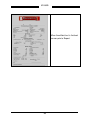
10 Lambda Equations used in the Gas Analyzer
The lambda equation used into the software PC, and into the firmware of the
gas Analyzer 810 is the Equation in fig. 10.1 .
[CO]
3.5
21 x [ [ CO2] + - - - - - - - [O2] + (Hcv / 4 x - - - - - - - - - - - - - - x 0.00877) x ([CO2] + [CO]) ]
2
3.5 + [CO] / [CO2]
λ = ----------------------------------------------------------------------------[CO ] / [CO2]
[ 21 + 0.5628 x] - - - - - - - - - - - - - - - x [ 1 + (Hcv / 4 ) - 0.01754 / 2] x [[CO2] + [CO] + [HC] x 6 x 10 - 4]
3.5 + [CO] / [CO2]
52