1
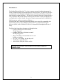
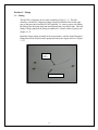
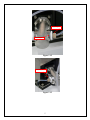
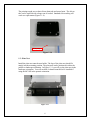
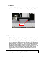
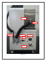
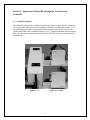
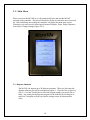
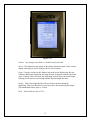
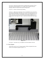
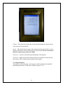
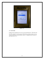
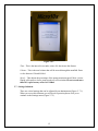
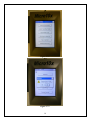
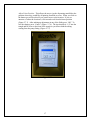
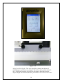
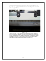
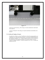
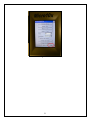
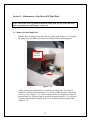
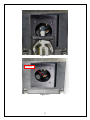
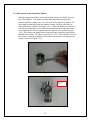
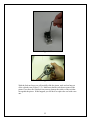
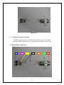
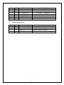
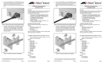
Micro10x User Manual Rev 2.1c 10 Stern Avenue, Springfield, NJ 07081 Tel: 973-376-7400 Fax: 973-376-8265 Index Introduction ............................................................................................................... 3 Section 1 - Setup ........................................................................................................ 4 1.1 - Tubing ..................................................................................................................... 4 1.2 - Plate Nest ................................................................................................................ 6 1.4 - External Cables ....................................................................................................... 7 Section 2 - Operation of Micro10X through the Touch Screen Controller ......... 9 2.1 - Controller Features ................................................................................................. 9 2.3 - Dispense Submenu ............................................................................................... 10 2.4 - Prime Submenu..................................................................................................... 12 2.5 - Empty Dispenser................................................................................................... 13 2.6 - Auto-Prime ........................................................................................................... 14 2.7 - Settings Submenu ................................................................................................. 15 2.8 - Starting and Stopping a Program .......................................................................... 20 Section 3 - Maintenance of the Mirco10X Fluid Path ......................................... 22 3.1 - Removal of the Pump Head .................................................................................. 22 3.2 - Disassembly of the Pump Head Module .............................................................. 24 3.3 – Cleaning of the Pump Assembly.......................................................................... 26 3.4 - Pump module Components ................................................................................... 26 3.5 - Additional Spare parts: ......................................................................................... 27 Section 4 – Micro10x Validation ............................................................................ 28 Section 4.1 – General Validation After Cleaning ......................................................... 28 Section 5 - Hardware Specifications...................................................................... 29 Section 5.1 - General..................................................................................................... 29 Section 5.2 - Mechanical Description ........................................................................... 29 Section 5.3 - Manifold .................................................................................................. 30 Section 5.4 - Dimensions .............................................................................................. 30 Section 5.5 - Electrical .................................................................................................. 30 Section 5.6 - Environmental ......................................................................................... 30 2 Introduction The Hudson Robotic Micro10x™ is a fast, compact, accurate benchtop instrument for reliable, automated bulk reagent dispensing into all microplates. The Micro10x provides a combination of fast filling speeds, high accuracy and extreme flexibility not found in other benchtop reagent dispensers. The Micro10x accurately dispenses volumes down to 1uL per channel, and provides features like tip-touch to ensure a clean, full dispense of even high surface-tension liquids. Its positive-displacement pump head is adjustable in 10nL increments, and never requires calibration. The Micro10x can be loaded and operated manually, but is also fully-compatible with robot loading systems, such as Hudson’s PlateCraneTM, or track-based microplate delivery systems, such as Hudson’s LabLinx, for unparalleled throughput and ease of setup. The Micro10x brings these advantages to lab applications: • Conserves bench space with its small, 7”x10” footprint • Graphical Image Row Selection to control the dispening pattern • Deep-well filling with controlled rise to avoid bubbles or foaming • 96-, 384-, 1536- filling, std and deep well • Tip Touch to control droplets • Autoclavable fluid path assures sterility Warning: To prevent fire, do not use Micro10x to dispense any type of flammable liquid. 3 Section 1 - Setup 1.1 - Tubing The MC10X is shipped with two tube assemblies (Figure 1.1.1). The tube assembly with the two Flangeless fittings should be installed between the right port on the pump head and the MC10X manifold. To create a proper seal tighten the fittings into the pump head and manifold until they stop finger tight. Once the fitting is finger tight turn the fitting an additional 1/8 turn to ensure a proper seal. (Figure 1.1.2) Install the longer tubing assembly in the same manner; with the single Flangeless fitting between the left port on the pump head and your reagent reservoir. (Figure 1.1.3) Tubing Pump to Reservoir Tubing Pump to Manifold Figure 1.1.1 4 Right pump port Manifold port Figure 1.1.2 Left pump port Figure 1.1.3 5 The priming trough uses a short silicon drain tube and waste basin. The silicon tube can be replaced with a longer one if needed. Standard silicon tubing will work as a replacement (Figure 1.1.4). Priming Trough Figure 1.1.4 1.2 - Plate Nest Install the plate nest onto the nest holder. The legs of the plate nest should fit snugly into the mounting position. The plate nest can be positioned in either the portrait or landscape orientation. In Figure 1.2.1 you will see the plate nest in the landscape orientation. You will need the 8-channel manifold to be installed if using the MC10X in the portrait orientation. Figure 1.2.1 6 1.3 - Manifold Install the manifold with the inlet port closest to the pump head. Use the provided thumbscrews to secure the manifold onto the mounting flange (Figure 1.3.6). Thumbscrews Figure 1.3.6 1.4 - External Cables The Micro10X Comes with a few cables that need to be installed into the rear of the unit before the unit can be turned on. The first cable is the pump cable, this is a black coiled cable that has two 90 connectors. The orientation of the cable does not matter when plugging the cable in. The pump cable is plugged into the rear of the pump on one side and the other side plugs into the right side connector on the rear of the MC10X (Figure 1.4.1). The second cable is the controller cable, this is the black coiled cable that is attached to the controller, this cable will get plugged into the left side connector on the rear of the MC10X (Figure 1.4.1). The last cable is the 24VDC power cable that will get plugged into the 4 position circular receptacle located on the right side rear panel of the MC10X (Figure 1.4.1). Note: The MC10x should only be operated with the supplied cables, no substitution is allowed unless replacement cable is supplied by Hudson Robotics. 7 Port for optional 4-way valve Pump Cable Controller Cable Pump Cable Serial Port DC Inlet for Power cord Figure 1.4.1 8 Power Switch Section 2 - Operation of Micro10X through the Touch Screen Controller 2.1 - Controller Features The Micro10X comes with a windows based touch screen to control the unit. On the top cover of the Micro10X there are two locations to slide the controller into (Figure 2.1.1). So it doesn’t matter which way the unit is facing, because you will able to access the control panel from either orientation (Figure 2.1.2). If either orientation is not accessible then you can keep the controller separate from the MC10X and leave it near the unit on the lab bench. Figure 2.1.2A &B Figure 2.1.1 9 2.2 - Main Menu When you power the MC10X up, it will automatically boot and start the MC10X program on the controller. The unit will also home all the axes when the unit is powered up. After initializing successfully the controller will display the main menu screen. From there you can access the following sub menus: Dispense, Prime, Empty Dispenser, Auto-Prime, Change Settings (Figure 2.2.1). Figure 2.2.1 2.3 - Dispense Submenu The MC10X can support up to 20 dispense programs. When you first enter the dispense submenu you will be at dispense program 1. Press the Next or Prev key (Fig. 2.2 1) on the Touch Panel to select the program number you would like to setup. Any setting for the dispense program can be modified by clicking on its menu bar. Doing this will put you into the settings screen for that particular value. 10 Figure 2.3.1 Volume – Any integer value from 1 to 9999uL may be selected. Speed – This adjusts the percentage of the pumps maximum speed. More viscous liquids will require a slower pump speed to avoid cavitation. Depth – Negative values are the distance below the travel height where the tips will move during the dispensing, allowing the user to dispense with the tips in the wells. Positive values will move the dispensing location above the travel height. Entering 0 will keep the travel height and the dispense height the same. Height – This is the height the tips will travel above the nest during the dispensing. This value should be at least 1mm above the measured plate height. The Standard Microtiter plate is ~15mm. Wells – Select from 96, 384 or 1536 11 Orientation– Select between the Portrait or Landscape plate orientation. This is determined by which manifold you are working with.12 channel will run in landscape while the 8 channel runs in portrait configuration. Tip Touch – Activate or deactivate tip touching. Tip Touch – Adjust where in the plate well you would like the tips to touch after the dispensing. Depending on the plate type, you will center your tips in row A of either a 96 or 384 well plate. Once the tip is centered you will adjust the Y-axis either to the front or rear of the well until the tip is touching the plates well. A good location for the height of the tip is ~1mm below the top of the Plate (Figure 2.3.2). Figure 2.3.2 Fill Pattern – Select the rows you would like to fill, the default is all wells. 2.4 - Prime Submenu The MC10X can store up to 10 prime programs. Fields are adjusted in the same manner as the Dispense programs (Figure 2.4 1). 12 Figure 2. 4.1 Volume – This is the total volume that will be primed through the system. Enter a value between 120 and 9999uL. Speed – This adjusts the percentage of the pumps maximum speed. More viscous liquids will require a slower pump speed to avoid cavitation. Do not exceed more than 30% speed on any value over 1000ul. Tip Touch – Activate or deactivate tip touching after each dispense. Tip Touch – Adjust where in the Priming trough you would like to touch the tips after a prime. This is helpful when running viscous liquids. 2.5 - Empty Dispenser This feature reverses the pump, removing most of the liquid from the manifold and tubing and returns it to the source container (Figure. 2.5 1). 13 Figure 2.5 1 2.6 - Auto-Prime Priming can be programmed to occur at a user specified interval. This allows the MC10X to dispense a certain amount of fluid into the priming trough to prevent evaporation during every specified time interval. Setting the time to 0 turns off this feature (Fig. 2.6.1). 14 Figure 2.6.1 Time – This is the interval in seconds; a time of 0 deactivates this feature Volume – This is the total volume that will be moved through the manifold. Enter a value between 120 and 9999uL. Speed – This adjusts the percentage of the pumps maximum speed. More viscous liquids will require a slower pump speed to avoid cavitation. Do not exceed more than 30% speed on any value over 1000ul. 2.7 - Settings Submenu There are critical settings that can be adjusted by an administrator (Figure. 2.7.1). When you access this submenu you will be ask a question please click yes to continue to the Settings menu (Figure 2.7.2) 15 Figure 2.7.1 Figure 2.7.2 16 Adjust Prime Position – This allows the user to jog the dispensing manifold to the position where they would like all priming functions to occur. When you click on the button you will be asked if you want to move to the location. If you are unaware of where the location is, click no and work from the home position (Figure 2.7.3). After making an adjustment in any of the fields press “OK”. To lose the changes press “Cancel” (Figure. 2.7.4). The tips should sit ~1/4” into the trough and be closer to the front of the trough so you do not kink the tubing coming from the pump fitting. (Figure 2.7.5) Figure 2.7.3 17 Figure 2.7.4 Figure 2.7.5 Adjust Track/Nest Height – This value should be evaluated and adjusted if manifold types or plate nests are changed. This will set the 0 position for the Zaxis. All dispense programs will reference this point to determine absolute dispense height. The manifold should be positioned as close to the surface of the 18 plate nest without touching it. To adjust, place a sheet of paper or business card on the plate nest. Jog the manifold down until it touches the paper but not pinch it to the nest. (Figure 2.7.6) Figure 2.7.6 Adjust Plate Origin – This value should be evaluated and adjusted if manifold types or plate nests are changed. This is the reference point for all well positions in a SBS standard plate. This is taught by aligning tip 1 on the manifold with the intersection of wells A1, A2, B1 and B2 in a 384 well plate. Tips 2-12 should align with every other well intersection in that row. (Figure 2.7.7) 19 Figure 2.7.7 Adjust Row/Column Spacing - This setting is set by the manufacturer and should not be adjusted. # Of Tips in Manifold - This setting is set by the manufacturer and should not be adjusted. 2.8 - Starting and Stopping a Program Press the Next or Prev key on the TouchScreen to select the program number you would like to run. When the desired program is selected press the RUN button on the TouchScreen (Figure 2.8.1). To stop a program, press the CANCEL button on the TouchScreen. The dispenser will pause, you may then choose to abort or continue the dispense program. To abort the program, press YES, to complete the program, press NO. 20 Figure 2.8.1 21 Section 3 - Maintenance of the Mirco10X Fluid Path Note: Please turn power off and disconnect all cables from the rear of the Micro10x before performing any maintenance on the unit. 3.1 - Removal of the Pump Head Remove the 4 mounting screws from the face of the pump (Figure 3.1.1). Support the pump with your hand to prevent it from falling from the mounting plate. 4 mounting screws for Pump head Figure 3.1 1 Gently pull the pump diagonally away from the mounting plate. Care must be taken not to pull the piston more than 1” out of the cylinder; damage to the piston seals may occur (Figure 3.1.2). Once the pump head is far enough away from the pump module you will slowly lift up on the entire pump assembly. You will need to remove the piston drive shaft from the pivot bearing inside the pump module (Figure 3.1.3). 22 Figure 3.1 2 Pivot Bearing Figure 3.1.3 23 3.2 - Disassembly of the Pump Head Module After the pump head module is removed from the pump you will able to access the Teflon adapters. The adapters lock the liner and piston into the proper position inside the cylinder case. You will remove the adapters by using a 5/8” open ended wrench and turning the adapters counter clockwise until they are removed from the cylinder case (Figure 3.2.1). When the adapters are removed you will notice that there are two flat surfaces machined in the liner that need to be re-aligned at the correct location before the adapters are re-installed (Figure 3.2.2). Now remove the pump bracket from the pump cylinder by removing the flathead screw using a 1/8” allen wrench (Figure. 3.2.3). This will allow access to the seal nut. Using an adjustable wrench remove the seal nut by turning the nut counter clock wise (Figure 3.2 4). Figure 3.2.1 Flat Spot on Liner Figure 3.2.2 24 Figure 3.2 3 Figure 3.2.4 With the Seal nut loose you will carefully slide the piston, seals and seal nut out of the cylinder case (Figure 3.2 5). Make sure that the seals do not come off the piston if you force the seals back on you may damage the surface of the seal that sits against the piston. If this happens you will have to replace the seal with a new one. 25 Figure 3.2.5 3.3 – Cleaning of the Pump Assembly All of the pump parts may be cleaned in an ultrasonic cleaner with a dilute detergent solution. The parts must be thoroughly rinsed prior to autoclaving. 3.4 - Pump module Components 1 2 3 4 26 5 6 7 Item # 1 2 3 4 5 6 7 QTY 1 1 2 1 1 2 1 Part Number PMP-1018 PMP-1021 PMP-1019 PMP-1017 PMP-1020 MCF1-18202-00 MCF1-18201-00 Description Cylinder Nut Gland Washer, ¼”. Teflon Lip Seal, ¼”, Rulon RA Q1C Cylinder Liner/Piston Set Cylinder Head Seal Adapter, Teflon Cylinder Case 3.5 - Additional Spare parts: Item # 1 2 3 4 QTY 1 1 1 1 Part Number MCF1-24000-00 MCF1-25000-00 MEC-1543 MEC-1544 Description Tubing, Pump to Manifold set Tubing, Pump to Reservoir set Dispense manifold, 8-channel Dispense manifold, 12-channel 27 Section 4 – Micro10x Validation Section 4.1 – General Validation After Cleaning To Ensure that the unit is dispensing properly after cleaning you will need to perform a validation dispense. To perform a validation dispense you will need the following items: Clear 96-well Polypropylene Plate Bulk reagent to dispense (preferably not clear) Optional- Sartorius WZA225-CW balance or similar with at least a 0.001mg readability. Setup a dispense program in the Micro10x to dispense 100ul into the 96-well plate. Make sure to prime the system properly so the unit is dispensing the bulk reagent without any air bubbles. Dispense into the entire plate, once the unit is finished dispensing you will inspect the plate. The inspect the plate you will raise the plate to eye level and visually inspect each well with the next in row A and H of the Plate. You want to make sure that the fluid makes a level horizontal line across the entire plate. If the fluid levels are not even, remove the manifold and clean/sonicate to clean. Run the test again after the manifold is re-cleaned. Optional: Before dispensing into the validation plate you will put it on the balance and tare the weight of the empty plate. Now take the plate and place it on the Micor10X nest and run the validation program. Once the program is completed you will weigh the plate on the balance. The Plate should weigh the following: 1uL of water ~ 1mg A 100ul/well 96-well plate ~ 9600mg ~2% tolerance @ 100ul Plate should weigh 9800mg - 9400mg 28 Section 5 - Hardware Specifications Section 5.1 - General NOTE: Specifications are subject to change without notice. Micro10X: Plate Format: Housing Material: Plate Nest Material Number of Axes 96, 384, or 1536 well plates in any shallow, Medium or Deep well-formatted SBS plate. Painted steel covering anodized cast aluminum housing Peek Three (X, Y and Z axes) Section 5.2 - Mechanical Description X-axis: Integrated stepper motor/stepper controller with encoder. This is a belt driven axis with pulley X-axis Travel Distance: ½” hard stop to hard stop X-axis Stepper Motor: Integrated 2048 encoder steps per revolution stepper motor. +/- 0.013mm resolution, approximately ½ second per revolution. Y-axis: Stepper motor linear actuators with 250 count encoder. Actuator has integrated 1/2” pitch Leadscrew. Controlled by separate stepper controller with encoder option. Y-axis Travel Distance: 5 ½” hard stop to hard stop Y-axis Stepper Motor 1000 encoder steps per revolution linear actuator. +/- 0.026mm resolution, approximately ½ second for entire travel distance. Z-axis: Stepper motor linear actuator. Actuator has integrated 9.74mm pitch Leadscrew. Controlled by separate stepper controller. Z-axis Travel Distance: 3 ¾” hard stop to hard stop Z-axis Stepper Motor: 200 steps per revolution linear actuator. +/- 0.006mm resolution, approximately ½ second for entire travel distance. Pump Module Material: Stainless steel covering anodized aluminum frame. Pump head Housing Material: Stainless steel casting Pump Material: Ceramic cylinder liner and Ceramic piston 29 Liner Bore Size: Tubing Material: Max Shot Size Min Shot Size Max Flow ¼” Peek fittings on Telfon tubing 225ul per revolution 12ul per revolution 0.225 lps (60% Max speed) Section 5.3 - Manifold Fixed Tip Manifold Material: Fixed tip Material: Peek Stainless Steel Section 5.4 - Dimensions 11½”H X 7”W X 10”D (Does not include Nest plate) 11½”H X 7”W X 15”D (Includes Nest Plate) Weight: ~15LBS Section 5.5 - Electrical Power Input: Fuses: Grounding: Computer Interface: 24VDC, 4A Internal T4.0 A/250 V Through the power cord, must be properly earth grounded RS-232 straight through serial cable Section 5.6 - Environmental Operating Temperature: Operating Humidity: Storage Temperature: Altitude: 15 to 40C (59 to 104F) 0 to 85%, no condensation -20 to 65C (-4 to 149F) Up to 2000m 30