1
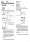
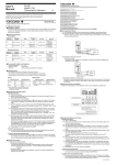
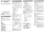
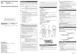
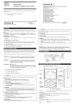
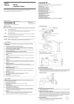
6.1 Connecting Procedure CAUTION ● Do not apply any voltage to the output terminals during signal generation. If voltage is applied by mistake, the internal circuit may be damaged. NOTE ● As the instrument is calibrated without the voltage drop of the lead cables, error due to the resistance of the lead cables (approximately 0.1 Ω for go and return) must be considered for load current measurement. 5.2 Generating DC Voltage The instrument generates voltage at a specified value through the output terminals. ■ Normal setting: <1> Switch the MEASURE/SOURCE selection switch to “SOURCE” (generation). This causes the display unit to show “SOURCE” and “ON.” <2> Select the range to be generated using the range selection rotary switch. The display unit shows an initial value and unit for each range. <3> Press the [▲]/[▼] keys under each digit to set an output value. <1> When connecting a thermocouple or the lead wires, they must be attached to the terminal adapter supplied with the instrument. <2> For measurements of the voltage, the resistance, or RTD in a two-wire connection configuration, connect the supplied lead cables to the terminals of the instrument, or the lead wires to the terminal adapter (see following Figure “a”). For measurements of the resistance or RTD in a three-wire connection configuration, connect the lead wires to the terminal adapter, or to the terminals of the instrument (see following Figure “b”). • Be sure to remove the short-bar (supplied) from the terminal adapter (supplied). • For measurements of the resistance or the RTD in a two-wire connection configuration, do not leave the lead wires connected to the 3W-Lo terminal. <3> Connect the clips on the other cable ends to the device under measurement. • For accurate measurement of the resistance or the RTD, make sure that the leading ends of the lead wires do not touch anything other than the device under measurement. a. Connection of the input terminals for measuring voltage, a thermocouple signal, the resistance in a two-wire connection configuration, or an RTD signal in a two-wire connection configuration 3W Lo Lo Hi Lo Hi b. Connection of the input terminals for measuring the resistance in a three-wire connection configuration and an RTD signal in a three-wire connection configuration 3W Lo Lo Hi RTD 5.3 Generating Resistance or RTD Signal The output terminals of the instrument generate resistance with a value that corresponds to the specified resistance value or the RTD temperature. <Switching between PT100 and JPT100> Use the range selection rotary switch to select the PT100 (JPT100) range. When the PT100 range is selected, press the SHIFT key to switch to the JPT100 range (“JPT100” is displayed). Press the SHIFT key again to return to the PT100 range. For the ITS90 and IPTS68 range settings, see Subsection 7.2, “Selecting Thermocouple Standard.” NOTE ● The method of simulating resistance output is by generating voltage according to the excitation current [I] received from the device under calibration, due to the equation: R (required resistance) = V (generated voltage)/I (current received from device) The device to be calibrated must have the excitation current for resistance measurement. ● The standard range of resistance-measuring current that the CA12E must receive from the resistance-measuring device under calibration is between 0.5 mA and 2 mA. When the current is above 2 mA, accurate resistance generation is not possible. When it is below 0.5 mA, the margin of error increases. For more information, see Section 9, “Specifications.” ● The generated resistance value is calibrated without taking the resistance value of the lead cables into consideration. Resistance value is increased by approximately 0.1 ⍀ at the lead cable ends. ● If capacitance between the terminals of the resistance-measuring device under calibration becomes 0.1 F or more, the CA12E may not be able to generate the correct resistance value. 5.4 Generating a Thermocouple (TC) Signal The instrument generates thermo-electromotive force from the output terminals, corresponding to the specified thermocouple (TC) temperature. <Selecting and switching thermocouple> Use the range selection rotary switch to select the type of thermocouple (TC) from J(U), T(L), N(B), and R(S). Use the SHIFT key to switch among U, L, B, and S. The selected type is shown in the Sub Seven Segment. <External RJ sensor and reference junction compensation> When a thermocouple (excluding B type) signal is generated and you directly calibrate a thermometer with a built-in reference junction compensation function without an external 0°C reference junction compensation means, use an RJ sensor (optional) as follows. (The built-in RJ sensor can also be used to carry out calibration (see Section 7, “Other Features”).). <1> Connect the RJ sensor to the RJ sensor input connector of the instrument. Insert the sensor so that the tab at the bottom of the connector is locked in. To release the connector, gently press the locking tab downward to unlock the connector, then remove it. <2> When the sensor is connected, the instrument displays “RJ-ON” and outputs a thermoelectromotive force based on the temperature detected by the RJ sensor. • The thermo-electromotive force is obtained by subtracting the value detected by the RJ sensor from the calculated thermo-electromotive force without the RJ sensor. • Compensation of output voltage according to the temperature detected by the RJ sensor is achieved by a sampling approximately every 4 seconds. Thus, there is a maximum delay of 4 seconds between the connection of the connector and the start of compensation. • For accurate compensation, an interval must lapse after connecting the RJ sensor to allow for temperature stabilization. Terminal adapter Terminal adapter 6.2 Measuring DC Voltage <1> Switch the MEASURE/SOURCE selection switch to MEASURE (measurement). MEASURE lights up on the display unit. <2> Select the range to be measured (100 mV) using the range selection rotary switch. The measured value is displayed. • If measured data is out of range or not measurable, the display unit shows “----.” 6.3 Measuring Resistance or RTD Signal <1> Switch the MEASURE/SOURCE selection switch to MEASURE (measurement). MEASURE lights up on the display unit. <2> Select the range to be measured using the range selection rotary switch. The measured value is displayed. • If measured data is out of range or not measurable, the display unit shows “----.” <Measuring RTD> Use the range selection rotary switch to select the PT100 (JPT100) range. When the PT100 range is selected, press the SHIFT key to switch to the JPT100 range (“JPT100” is displayed). Press the SHIFT key again to return to the PT100 range. For the ITS90 and IPTS68 range settings, see Subsection 7.2, “Selecting Thermocouple Standard.” 6.4 Measuring Thermocouple <1> Switch the MEASURE/SOURCE selection switch to MEASURE (measurement). MEASURE lights up on the display unit. <2> Select the thermocouple (J(U), T(L), N(B), or R(S)) to be measured using the range selection rotary switch. Use the SHIFT key to switch among U, L, B, and S. • The display unit shows the results of the corresponding temperature on which the internal RJ sensor-measured temperature compensation was based. • If the input terminals are open, the display unit shows “-bo-” (burnout). • If the measurement data is out of range or not measurable, the display unit shows “----” (If the temperature in the operating environment of the instrument changes rapidly, wait until RJ compensation stabilizes and then use the instrument). 7. Other Features The following features are available depending on the settings of the DIP switches above the battery holder, which can be accessed by removing the cover from the back of the instrument. DIP switches ON 1 2 3 4 1: Reference junction compensation by the internal RJ sensor 2: Temperature 3: Setting of thermocouple standard (OFF: ITS90/ON: IPTS68) 4: Disable automatic power off 7.1 Reference Junction Compensation by the Internal RJ Sensor When generating a thermocouple signal, setting DIP switch 1 to “ON” enables the instrument's internal RJ sensor to output a temperature compensated thermo-electromotive force. 7.2 Temperature NOTE ● Be sure to remove the RJ sensor from the connector of the instrument when reference junction compensation is not necessary. 6. Measurement WARNING ● When connecting the device under measurement, turn off the power of the device. Connecting/disconnecting the lead cables for measurement without turning off the power of the device under measurement may be extremely dangerous. ● Special care should be taken to avoid connecting a current circuit to the input terminals. Inadvertent connection may not only cause damage to the circuit or device under measurement and the instrument, but may also be dangerous to personnel. ● The maximum allowable voltage between all input/output terminals and ground is 42 V. Any voltage exceeding this level may not only damage the instrument, but also cause injury to personnel. Never attempt to apply such voltage. Check that the DIP switch 2 should be placed in the OFF position. 7.3 Selecting Thermocouple Standard When selecting the range of the PT100 (JPT100), use DIP switch 3 to select the temperature scale standard. OFF: ITS90 ON: IPTS68 (“68” appears in the Sub Seven Segment) JPT100 is of the IPTS68 standard, so its temperature scale cannot be set using DIP switch 3 (For RTD generation and measurement, the SHIFT key can be used to switch between the PT100 and the JPT100). 7.4 Disabling Automatic Power Off According to the factory setting of the instrument, it automatically turns itself off if not operated for about 10 minutes. By setting DIP switch 4 to “ON,” this function can be disabled. However, when the instrument is battery-driven, it is generally recommended that this switch be set to “OFF” in order to prevent the batteries from being exhausted. CAUTION ● Do not apply any voltage to the input terminals that is above the measurement range. This may damage the instrument. IM CA12E-01E <2>