1
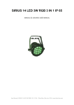
SIRIUS 21 LED 3W RGB 3in1 IP65 USER MANUAL User Manual | SIRIUS 21 LED 3W RGB IP65 Triton Blue | Rev.Jan. 2014 | www.triton-blue.com For your own safety, please read this user manual carefully before you initially start-up Every person involved with the installation, operation and maintenance of this device has to: -Be qualified. -Follow the instructions of this manual. -Consider this manual to be part of the total product. -Keep this manual for the entire service life of the product -Pass this manual on to every further owner or use of the product. -Download the last version of the user manual from the internet in www.triton-blue.com 1 BEFORE YOU USING Include SIRUS 21 LED 3W RGB 3in1 RGB x 1 Power cable with plug x 1 DMX input cable x 1 User Manual x 1 Unpacking Thank you for purchasing this Product. Every Product been thoroughly tested and has been transported in perfect operating condition. Carefully check the carton for damage that may have occurred during transporting. lf the carton appears to be damaged, carefully inspect your fixture for any damage and be sure all accessories necessary to operate the unit has arrived intact. carefully unpack the carton, check the contents to ensure that all parts are present, and have been received in good condition. AC Power This fixture has an auto-switching power supply that can accommodate a wide range of input voltages. The only thing necessary to do before powering on the unit is to make sure the line voltage you are applying is within the range of accepted voltages. This fixture will accommodate between 100V and 240V AC 50-60 Hz. All fixtures must be powered directly off a switched circuit and cannot be run off a rheostat (variable resistor or dimmer circuit, even if the rheostat or dimmer channel is used solely for a 0% to 100% switch. Safety Precautions Please read these instructions carefully, which includes important information about the installation, usage and maintenance of this product. Please keep this User Guide for future consultation. lf you sell the unit to another user, be sure that they also receive this instruction booklet. Do not spill water or other liquids into or on to your unit. Be sure that the local power outlet match that of the required voltage for your unit. Do not attempt to operate this unit if the power cord has been frayed or broken. Do not attempt to remove or break off the ground prong from the electrical cord. This prong is used to reduce the risk of electrical shock and fire in case of an internal short. User Manual | SIRIUS 21 LED 3W RGB IP65 Triton Blue | Rev.Jan. 2014 | www.triton-blue.com Disconnect from main power before making any type of connection. Do not remove the cover under any conditions. There are no user serviceable parts inside. Never operate this unit when the cover is removed. Never plug this unit in to a dimmer pack Always be sure to mount this unit in an area that will allow proper ventilation. Allow about 6” (15cm) between this device and a wall. Do not attempt to operate this unit, if it becomes damaged. During long periods of non-use, disconnect the unit’s main power. Always mount this unit in safe and stable matter. Power-supply cords should be routed so that they are not likely to be walked on or pinched by items placed upon or against them, paying particular attention to the point they exit from the unit. Cleaning - The fixture should be cleaned only as recommended by the manufacturer. Heat -The appliance should be situated away from heat sources such as radiators, heat registers, stoves, or other appliances (including amplifiers) that produce heat. The fixture should be serviced by qualified service personnel when: A. The power-supply cord or the plug has been damaged. B. Objects have fallen, or liquid has been spilled into the appliance. C. The appliance has been exposed to rain or water. D. The appliance does not appear to operate normally or exhibits a marked change in performance Do not daisy chain power to more than 10 units @ 120V and 20 units @ 230V. To prevent or reduce the risk of electrical shock or fire, do not expose this unit to rain or moisture. There are no user serviceable parts inside this unit. Do not attempt any repairs yourself, doing so will void your manufactures warranty. LED Expected Lifespan LEDs gradually decline in brightness over time. HEAT is the dominant factor that leads to the acceleration of this decline. Packaged in clusters, LEDs exhibit higher operating temperatures than in ideal or singular optimum conditions. For this reason when all color LEDs are used at their fullest intensity, life of the LEDs is significantly reduced. lt is estimated that a viable lifespan of 40,000 to 50,000 hours will be achieved under normal operational conditions. lf improving on this lifespan expectancy is of a higher priority, place care in providing for lower operational temperatures. This may include climatic-environmental and the reduction of overall projection intensity. 2. INTRODUCTION Features Features 3, 4, 5, 6 or 11-channel DMX-512 LED wash light (with ID addressing) Operating modes 3-channel: RGB control 3-channel: HSV control (hue, saturation and value) 4-channel: RGB , dimmer 4-channel: RGBW control 5-channel: RGBW ,dimmer 6-channel: RGBW, dimmer, strobe 11-channel: RGBW, ID, dimmer, strobe, auto, auto speed, custom programm, dimmer speed RGB color mixing Light Source: 21 x 3W 3 in 1 LEDs Life: 80000 hours Lens: Standard 35°;; optional 45° degree Color Changing, Color mixing, Strobe, Dim 0%-100%, speed adjustment, etc. DMX 512/Auto Run/Master Slave Material: Aluminum body User Manual | SIRIUS 21 LED 3W RGB IP65 Triton Blue | Rev.Jan. 2014 | www.triton-blue.com Protection rating: IP66 Power consumption: 80w Voltage: 110v-240v 50Hz/60Hz Power supply: Built-in and auto switching Size: L300 x W300 x H350mm Net Weight: 6kg G.W.: 7kg Temperature control make the light works in safety condition DMX Channel Summary This Product has a total of 7 DMX channel configurations, referred to as “Personalities” in this manual and in the fixture onboard control board. The 7 personalities are [STAG, Arc.1, Ar1.D, Arc.2, Ar2.d, Ar2.s, and HSV]. Each of the different personalities can be accessed from the control panel. Please see section on “Control Panel Functions” on a description on how to accomplish this. HSV STAG ARC. 1 Arl. d Arl, S Channel 1 2 3 Channel 1 2 3 4 5 6 7 8 10 Channel Description Hue Saturation Value (brightness) Description Dimmer Red (set the step time when pr. 01-10 is set Green (set the fade time when pr. 01-11 is set Blue Color change/white balance Strobe Auto/custom program Speed of auto ID address Description 1 2 3 Channel 1 2 3 4 Channel 1 2 3 4 5 Red Green Blue Description Dimmer Red Green Blue Description Dimmer Red Green White Strobe 3. SETUP Power Supply Before plugging your unit in, be sure the source voltage in your area matches the required voltage for your equipment. This fixture has an auto-switching switch-mode power supply that can accommodate a wide range of input voltages. The only thing necessary to do before powering on the unit is to make sure the line voltage you are applying is within the range of accepted voltages. This fixture will accommdate between 100V and 240V AC 50-60 Hz. All fixtures must be powered directly off a switched circuit and cannot be run off a rheostat (variable resistor) or dimmer circuit, even if the rheostat or dimmer channel is used solely for a 0% to 100% switch. This fixture is User Manual | SIRIUS 21 LED 3W RGB IP65 Triton Blue | Rev.Jan. 2014 | www.triton-blue.com designed for power linking from one TS104 to another TS104 fixture. Each fixture ships with IP-65 proprietary power input cables. Each fixture ships with a power adapter to Male Edison connector. All fixtures must be connected to circuits with a suitable Earth Ground. Depending on the application, the lighting fixture may require a different connector Please refer to the below wire color code if installing a new connector. Wire Connection Pin Brown AC Live 1 Blue AC Neutral 2 Green/Yellow AC Ground 3 Mounting This fixture may be mounted in any safe position. The fixture includes a mounting yoke to which a rigging clamp can be attached. You must supply your own clamp and make sure the clamp is capable of supporting the weight of this fixture. lt is recommended to use at least 2 mounting points per fixture. You can order “C” and “O”-clamps. Note: There are 2 types of applications for this fixture: floor stand for up lighting, and overhead use for down lighting. lf you are using this fixture for up lighting, then you must use at least 1 safety cable/chain for each fixture in addition to the mounting brackets. 1. lf hanging the fixture for over head use, then please follow the below steps. 2. Block access below the work area and use suitable and stable platform when installing or servicing fixture. 3. Ssfety cables must always be used, secured through safety cable attachment. The safety cable must be capable of holding 10 times the weight of the fixture. 4. Verify the structure can hold 10 times the weight of all to-be install ed fixtures. After prolonged periods of operation, the fixture chassis may reach high temperatures. This fixture must be mounted in a ventilated location, as it is convection cooled. Fixture Linking You will need a serial data link to run light shows of one or more fixtures using a DMX-512 controller to run synchronized shows on two or more fixtures set to a master/slave operating mode, The combined number of channels required by all the fixtures on a serial data link determines the number of fixtures the data link can support. lmportant: Fixtures on a serial data link must be daisy chained in one single line. To comply with the EIA-485 standard no more than 32 devices should be connected on one data link. Connecting more than 32 fixtures on one serial data link without the use of a DMX optically-isolated splitter may result in deterioration of the digital DMX signal. Maximum recommended serial data link distance: 500 meters (1640 ft.) Maximum recommended number of fixtures on a serial data link: 32 fixtures User Manual | SIRIUS 21 LED 3W RGB IP65 Triton Blue | Rev.Jan. 2014 | www.triton-blue.com Data Cabling To link fixtures together you must obtain data cables. You can purchase certified DMX cables directly from a dealer/distributor or construct your own cable. If you choose to create your own cable please use data-grade cables that can carry a high quality signal and are less prone to electromagnetic interference. DMX DATA CABLE Use a Belden© 9841 or equivalent cable which meets the specifications for EIA RS-485 applications. Standard microphone cables cannot transmit DMX data reliably over long distances. The cable will have the following characteristics: 2-conductor twisted pair plus a shield Maximum capacitance between conductors _ 30 pF/ft. Maximum capacitance between conductor and shield _ 55 pF/ft. Maximum resistance of 20 ohms / 1000 ft. Nominal impedance 100 _ 140 ohms CABLE CONNECTORS Cabling must have a male XLR connector on one end and a female XLR connector on the other end. CAUTION Do not allow contact between the common and the fixture’s chassis ground. Grounding the common can cause a ground loop, and your fixture may perform erratically. Test cables with an ohm meter to verify correct polarity and to make sure the pins are not grounded or shorted to the shield or each other. 3-PIN TO 5-PIN CONVERSION CHART Note! lf you use a controller with a 5 pin DMX output connector, you will need to use a 5 pin to 3 pin adapter. The chart below details a proper cable conversion: 3 PIN to 5 PIN CONVERSION CHART Conductor Ground/Shield Data (-) signal Data (+) signal Do not use Do not use 2 Pin Female (output) Pin 1 Pin 2 Pin 3 5 Pin Male (Input) Pin 1 Pin 2 Pin 3 Do not use Donot use User Manual | SIRIUS 21 LED 3W RGB IP65 Triton Blue | Rev.Jan. 2014 | www.triton-blue.com Setting up a DMX Serial Data Link 1. Connect the (male) 3 pin connector side of the DMX cable to the output (female) 3 pin connector of the controller. 2. Connect the end of the cable coming from the controller which will have a (female) 3 pin connector to the input connector of thenext fixture consisting of a (male) 3 pin connector. 3. Then, proceed to connect from the output as stated above to the input of the following fixture and so on. Master/Slave Fixture Linking 1. Connect the (male) 3 pin connector side of the DMX cable to the output (female) 3 pin connector of the first fixture. 2. Connect the end of the cable coming from the first fixture which will have a (female) 3 pin connector to the input connector of the next fixture consisting of a (male) 3 pin connector. Then, proceed to connect from the output as stated above to the input of the following fixture and so on. 4. OPERATING INSTRUCTIONS Control Options The equipment is addressable in the DMX range of 001 to 512. ln its simplest control form, this allows for the control of up to 56 fixtures in the11-channel “STAG” personality;; however, a secondary “ID” address system exists for use in a limited DMX universe and architectural environments. The “ID” address system allows the user to assign up to 66 fixtures within the same DMX address;; in effect, multiplying the control of the equipment within a single universe to 3,696 fixtures. The equipment “ID” address system is accessed using DMX channel 11 [STAG]. Consideration must be placed when programming live performances or cues that need to trigger on demand or on a time line. So, to remain within one second execution time, program no greater than 10 fixtures on ID addressing per DMX channel. User Manual | SIRIUS 21 LED 3W RGB IP65 Triton Blue | Rev.Jan. 2014 | www.triton-blue.com Control Quick Setup For detailed instructions on display panel operations and functions please advance to the section titled;; “Display Panel Functions”. These steps assume that you have read and are familiar with setting up a DMX serial data link. DMX-512 control without “ID” address The equipment operates on 11 channels of DMX (“STAG” personality). Address each fixture in increments of10channels. (l.e.1,11,21,31, etc...) To save time you can use the same DMX address for each fixture. All fixtures will then respond simultaneously to control. You may also group your fixtures and address those groups alike for faster programming and control. 1. Access the control panel function by pressing the “MENU” button until the ‘RUN MODE’ is displayed. Press “ENTER” and use the “UP/DOWN” buttons to select ‘DMX’ function. Then, Press “MENU” button until ‘DMX512 ADDRESS’ is displayed. Use the “UP/DOWN” buttons to increase or decrease channels between 001 and 512. 2. Press the (ENTER) button to confirm action. Then press “MENU” to exit. Deactivate ID addressing in each fixture by setting panel function ‘ID ON/OFF’ to OFF. “SET” to “ID ON/OFF” to “OFF” DMX-512 addressing with ID address 1. Follow instructions 1 for DMX512 addressing. 2. Activate ID addressing in each fixture by setting panel function “ID ON/OFF” to ON. “Settings” to “ID ON/OFF” to “ON” For every DMX512 starting address the user can set 66 separate ID addresses. Set.ID addresses in each fixture by setting panel function“ID address” to incremental values.(l.e. 1,12,24,36 etc...) “Settings” to “address ” to“01 ~ 66 ” Setting the DMX address Each fixture requires a start address from 1 to 512. A fixture requiring one or more channels for control begins to read the data on the channel indicated by the start address. For example, a fixture that occupies or uses 5 channels of DMX and was addressed to start on DMX channel 100, would read data from channels: 100, 101, 102, 103,and 105. Choose start addresses so that the channels used do not overlap and note the start address selected for future reference. The equipment uses up to11channels of DMX. lf this is your first time using DMX, we recommend reading the DMX Primer in the Appendix Section. Control Panel Functions All fixture functions and settings are accessible via the built-in control panel interface. User Manual | SIRIUS 21 LED 3W RGB IP65 Triton Blue | Rev.Jan. 2014 | www.triton-blue.com User Manual | SIRIUS 21 LED 3W RGB IP65 Triton Blue | Rev.Jan. 2014 | www.triton-blue.com User Manual | SIRIUS 21 LED 3W RGB IP65 Triton Blue | Rev.Jan. 2014 | www.triton-blue.com User Manual | SIRIUS 21 LED 3W RGB IP65 Triton Blue | Rev.Jan. 2014 | www.triton-blue.com User Manual | SIRIUS 21 LED 3W RGB IP65 Triton Blue | Rev.Jan. 2014 | www.triton-blue.com DMX512 Chnnnel Values User Manual | SIRIUS 21 LED 3W RGB IP65 Triton Blue | Rev.Jan. 2014 | www.triton-blue.com Important Notes about STAG DMX Operation User Manual | SIRIUS 21 LED 3W RGB IP65 Triton Blue | Rev.Jan. 2014 | www.triton-blue.com MASTER DIMMER Channels 1 control the intensity of the currently projected color When the slider is at the highest position (255), then the intensity of the output is at the maximum. User Manual | SIRIUS 21 LED 3W RGB IP65 Triton Blue | Rev.Jan. 2014 | www.triton-blue.com 16 DMX Primer There are 512 channels in a DMX-512 connection. Channels may be assigned in anyt manner. A fixture capable of receiving DMX 512 will require one or a number of sequential channels. The user must assign a starting address on the fixture that indicates the first channel reserved in the controller. There are many different types of DMX controllable fixtures and they all may vary in the total number of channels required. Choosing a start address should be planned in advance. Channels should never overlap. lftthey do, this will result in erratic operation of the fixtures whose starting address is set incorrectly. You can however, control multiple fixtures of the same type using the same starting address as long as the intended result is that of unison movement or operation, ln other words, the fixtures will be slaved together and all respond exactly the same. DMX fixtures are designed to receive data through a serial Daisy Chain. A Daisy Chain conneetion is where the DATA OUT of one fixture connects to the DATA IN of the next fixture. The order in which the fixtures are connected is not important and has no effect on how a controller communicates to each fixture. Use an order that provides for the easiest and most direct cabling. Connect fixtures using shielded two conductor twisted pair cable with three pin XLR male to female connectors. The shield connection is pin 1, while pin 2 is Data Negative (S-) and pin 3 is Data positive (S+). User Manual | SIRIUS 21 LED 3W RGB IP65 Triton Blue | Rev.Jan. 2014 | www.triton-blue.com