1
FieldMaster™ GS
Power/Energy Analyzer
User Manual
FieldMaster GS
FieldMaster™ GS
Power/Energy Analyzer
User Manual
Software Version 2.10
Manual Part Number 0217-378-00 EA
© 2002, Coherent, Inc.
1
FieldMaster GS
2
FieldMaster GS
Contents
General Description ............................................................................ 1
Features ........................................................................................ 2
Unpacking .......................................................................................... 4
Controls & Connections ..................................................................... 5
Front Panel ................................................................................... 5
Side Panel ..................................................................................... 6
Setup .................................................................................................. 7
Turn On ....................................................................................... 7
Screens ................................................................................................ 8
Over Temperature ........................................................................ 8
Screens: Menu .............................................................................. 9
Invert Display ............................................................................... 9
Backlight ...................................................................................... 9
Contrast ....................................................................................... 9
Auto Off .................................................................................... 10
Alog Out .................................................................................... 10
TermChar ................................................................................... 10
System Status ............................................................................. 10
Home Screen - Quadrant Thermal Detector Head CW .................... 11
Offset ......................................................................................... 12
Setup .......................................................................................... 12
Align .......................................................................................... 13
Energy (Quadrant Thermal Detector
Single Pulse Operation) .............................................................. 18
Home Screen - Non-Quadrant Detector Head CW .......................... 20
Offset ......................................................................................... 20
Setup .......................................................................................... 20
Home Screen - Pulse Detector .......................................................... 21
Clear .......................................................................................... 22
Auto ........................................................................................... 22
Range ......................................................................................... 23
Setup .......................................................................................... 23
Screens: Tune .................................................................................... 24
Reset .......................................................................................... 25
Auto ........................................................................................... 25
Range ......................................................................................... 26
Trend Screen ..................................................................................... 26
Setup .......................................................................................... 27
Scroll .......................................................................................... 29
3
FieldMaster GS
Contents
4
Start ........................................................................................... 30
Remote Control ................................................................................ 37
Introduction ............................................................................... 37
Making the Software Connection ............................................... 37
Message Exchange Protocol ........................................................ 37
Data Connections ...................................................................... 38
Remote Control Language Syntax .............................................. 39
Commands and Command Parameters ................................ 39
Query Commands ............................................................... 40
Case Sensitivity .................................................................... 40
Program Messages ................................................................ 40
Remote Control Commands ...................................................... 41
Remote Control Error Codes ............................................... 42
Command Errors ................................................................. 42
Remote Control Screen Display ........................................... 43
System Configuration Commands ....................................... 43
System Configuration Queries ............................................. 45
Data Collection Commands ................................................ 47
Data Collection Queries ...................................................... 50
Simple RS-232 Program Example............................................... 58
Simple RS-232 Program Example (Cont'd) ................................ 59
Simple RS-232 Program Example (Cont'd) ................................ 60
Determining Firmware Version ......................................................... 61
Maintenance ..................................................................................... 61
Trouble Shooting .............................................................................. 62
Specifications .................................................................................... 63
Appendix A: FieldMaster GS Block Diagram and Circuit Operation
Appendix B: Help File
Sales & Service Information
Warranty
FieldMaster GS
General
Description
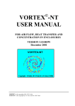
Figure 1. FieldMaster™ GS Power/Energy Analyzer
The FieldMaster™ GS is a rugged, compact, microprocessor based power
and energy analyzer that interfaces with the full line of Coherent "smart"
power and energy detector heads. FieldMaster GS provides a unique combination of an analog meter for laser tuning, a precise digital display, and
graphics analysis of power or energy on a high resolution LCD display.
The FieldMaster GS can be used with all lasers commonly manufactured
today – CW and pulsed, from the UV to the IR, with rated power from
nanowatts to kilowatts – simply by plugging the appropriate detector
head into the console.
1
FieldMaster GS
General
Description
(cont'd)
Features
Features of the FieldMaster GS are described below.
Pulsed/CW Measurement
The FieldMaster GS supports CW power measurement and Pulse energy
measurement. (See Appendix A for a list of heads supported.)
•
Pyroelectric Detectors – A complete family of energy measurement pyroelectric detectors for single pulse or pulse train from
1.0µJ to 20 J.
•
Semiconductor and Thermal Detectors – FieldMaster GS is
compatible with semiconductor detectors and the full range of
Coherent’s patented thermal disk Smart Detector Heads, providing power measurement capability from 1 nW to 5 kW.
Versatility
More than just a power/energy meter, the FieldMaster GS also provides
complete power and energy trend information, beam position drift measurement, statistics, and tuning.
Communications
The FieldMaster GS supports the following communication modes:
•
Analog Out – Provides 0-1 Volt output at 5Hz update rate to
operate an external device such as a chart recorder.
•
RS-232 Interface – Standard RS-232 interface for full interactive operation of the FieldMaster GS by a computer. The
interface can also be used to download data from the unit to a
computer for storage, graphing and analysis.
Hot Detector Head Swapping
The FieldMaster GS allows swapping of detector heads while power remains On. After a swap, the unit reboots with the correct settings for the
new detector head.
2
FieldMaster GS
General
Description
(cont'd)
Smart Detector Technology
FieldMaster GS detector heads utilize Coherent’s Smart Detector Technology. Each detector head has an EEPROM which stores the characteristics
and calibration data for the detector. This information is read by the
FieldMaster console at start-up, eliminating the need to make manual
changes to the console when changing detectors. NOTE: This does not
refer to user required entries for Display Average, Wavelength, and Attenuation.
Analog Sensitivity and Feedback
The analog meter movement in the FieldMaster GS gives fast, smooth
feedback and provides the fast response time necessary for laser tuning.
Digital Precision
The FieldMaster GS unique high resolution LCD graphic display provides precise digital readout of power or energy as well as indicators for
warning or error conditions and graphic analysis of data collection.
Beam Alignment
Thermal disk CW sensors provide a quadrant display of beam position
on the detector head. Centering the beam on the detector head achieves
maximum accuracy.
Broad Wavelength Range
FieldMaster detectors cover the spectrum from 0.19 to 10.6 µmeters.
Ease of Use
FieldMaster GS controls on the front panel and the simplified menu structure provide ease of use with minimal training. All adjustments for different detector heads are handled automatically using Smart Detector Technology.
Portability
The compact, lightweight console and internal rechargeable battery pack
create a system that is easily transported from lab to lab, or around the
world.
3
FieldMaster GS
General
Description
(cont'd)
Reliability
The FieldMaster GS, with its integral cover, is designed to withstand
the rigors of travel and regular field use. Coherent’s rugged detector
head design has been the industry standard for more than 30 years.
Accuracy
The combination of Smart Detector Technology, laser wavelength
entry, and accurate beam positioning information create a highly accurate laser measurement system.
Unpacking
The FieldMaster GS console and detector heads are shipped in foam
inserts. Batteries are installed in the console prior to shipment. To
insure correct battery operation, the batteries require an initial over
night (16 hours) charging.
Visually check all cartons for damage before unpacking. If there is no
visible damage, remove all items from the cartons and inspect for
damage. Advise Coherent of any damage immediately. A Returned
Material Authorization will be issued for any damaged instruments
(see the last page of this manual for Service).
4
FieldMaster GS
Controls
& Connections
Screen
Display
Soft Keys
On/Off Key
Cursor
Control Pad
Function
Keys
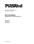
Figure 2. Front Panel Controls
Front Panel
In addition to the LCD graphics screen, all controls for the FieldMaster
GS are on the front panel (see Figure 2). Controls consist of:
• Soft Keys – The four soft keys, shaped like arrow heads, are
immediately under the display screen. Use these keys to select,
set, and change various operating functions displayed on the
screen.
•Function Keys – Use these oval keys to select one of the four
main display and analysis screens. These are "hot" keys (i.e.,
always active).
• ON/OFF – Use this oval key to turn FieldMaster GS power On
and Off.
• Cursor Control Pad – This circle with a small arrow head in each
quadrant controls the movement of the cursor on a display. Use
the up and down arrows to select the next or previous item
(highlighted); the left and right arrows to move left and right on
highlighted digits within a highlighted item. The cursor wraps
up or down within a list, and left or right within a set of digits.
5
FieldMaster GS
Controls
& Connections
(cont'd)
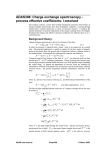
Side Panel
The side panel of the FieldMaster GS console (see Figure 3) has a female
DB25 type connector, a female DB9 type connector, an RCA connector,
and the power connector.
Connect the detector to the DB25 connector. The FieldMaster GS is designed for use with only Coherent’s Smart Detector Heads. Do not plug
other types of detectors into the FieldMaster GS console.
If using a computer for remote control and data transfers, connect it to
the DB9 connector (RS-232 interface).
To drive an external device such as a strip chart printer, connect it to the
RCA connector which provides a 0 to 1V analog output. (An RCA-toBNC adapter is stored in the battery compartment.)
Connect the power supply provided with the FieldMaster GS for regulated 9VDC 0.4A power. Use only the provided Coherent power supply.
DB25 Detector Socket
(Use only Coherent Smart
Detector Heads)
DB9 RS-232 Connector
Computer Interface
RCA connector for
Analog Out
Power Socket Regulated
9VDC 0.4A Power Supply
(Use only Coherent AC Adaptor)
(+)
)-(
Power connector polarity
Figure 3. Side Panel Connectors
6
FieldMaster GS
Setup
The front cover of the FieldMaster also serves as the stand for the unit.
Rotate the cover down around the back of the unit and place on a convenient surface.
The FieldMaster GS may be powered by using the provided AC Adapter
or by using the factory installed rechargeable batteries. If using the AC
Adaptor, plug it into a 110 VAC outlet (in Europe, 220 VAC) and connect it to the AC Adapter connector on the left side of the FieldMaster GS
(see Figure 3).
If using battery power, The Home, Tune and Trend screens provide a
LOW BATTERY WARNING indication when there is 10% of battery
life remaining. Plug the unit into an AC outlet to recharge the batteries.
Plug the detector head into the DB25 connector on the left side of the
console. The unit is now ready to turn power on.
CAUTION: Insure that your detector head is rated for
the power or energy density of your laser. Power or
energy density greater than the rating of the sensor will
damage the detector head.
Turn On
Press the On/Off key on the front panel. The unit beeps once and the
screen displays the System Status of the FieldMaster GS for approximately
5 seconds.
A query is sent to the EEPROM in the detector head.
If no detector head is plugged in or either the detector head or detector
cable is defective, the message NO DETECTOR will be displayed on the
System Status screen, and the unit will beep continuously every 10 seconds.
When the self tests are completed and the parameters for the detector
have been loaded, the Home screen appears.
7
FieldMaster GS
Screens
Operation and use of the FieldMaster GS is through the various display
and analysis screens and the ability they provide to setup and control the
system. There are four primary screens which correspond to the front
panel function keys. The Menu screen provides basic, system wide control functions.
The information displayed on the Home screen is detector head dependent. The other two analysis screens - Tune and Trend - provide controls
which are consistent across all detector heads.
Over Temperature
If the temperature at the detector head sensor exceeds the maximum operating temperature at any time, the screen will go blank and then OVER
TEMP will appear in the middle of the screen. After 5 seconds, the unit
reads the sensor temperature again. If the temperature is still over limit,
OVER TEMP returns. If the temperature is within limits, normal operation resumes.
Screens: Menu
Menu Screen
Press the MENU Function key to display the Menu screen shown in Figure 4. When this screen appears, the top item is highlighted to indicate it
is the current selection. Items on the Menu screen are described below. In
this screen:
Press ENTER to enable any changes made and return to the Home
screen.
Press ESCAPE to negate any changes and return to the Home screen.
On the Cursor Control pad, press the up and down arrows to select
the next or previous item (highlighted); press the left and right arrows
to move left and right on highlighted digits within a highlighted item.
The cursor wraps up or down within a list, and left or right within a
set of digits.
8
FieldMaster GS
Screens: Menu
(cont'd)
Figure 4. MENU Screen
Invert Display
Use this item with the INC/ON and DEC/OFF soft keys to turn the
reverse display mode On or Off. This is a personal preference parameter.
Default mode is Off with black text on a white background. Note that
this setting is retained in nonvolatile memory during On/Off cycles and
regardless of the detector connected.
Backlight
Use this item with the INC/ON and DEC/OFF soft keys to turn the
backlight Off and On. Default mode is On and recommended for normal use, and under low ambient light conditions. In this mode, battery
power will last approximately 4 hours. Note that this setting is retained in
nonvolatile memory during On/Off cycles and regardless of the detector
connected.
Contrast
Use this item with the INC/ON and DEC/OFF soft keys to increase or
decrease the contrast from 0 (dark) to 100 (light). Default setting is 50.
Note that this setting is retained in nonvolatile memory during On/Off
cycles and regardless of the detector connected.
9
FieldMaster GS
Screens: Menu
(cont'd)
Auto Off
Use this item with the INC/ON and DEC/OFF soft keys to change the
time in minutes that the unit will stay on between key presses before
automatically turning off. Default setting is 0 with the maximum being
480. The Auto Off mode is disabled if set to 0. This feature is only functional when using battery power.
Alog Out
Use this item with the INC/ON and DEC/OFF soft keys to adjust the
full scale power/energy range at the Analog Out side panel connector.
This output, equivalent to 1VDC, is from a 12-bit D/A which provides
an output impedance of 1.5K ohms. No other screen functions will change
this range. This setting, retained in nonvolatile memory during On/Off
cycles, reverts to default if a different detector is plugged in.
NOTES: Analog out is not active in trend mode if data is not being collected. In pulse mode, clear or reset keys do not clear the value on the
analog out.
TermChar
Use this item with the INC/ON and DEC/OFF soft keys to set the
RS-232 communication termination character the FieldMaster GS and
host computer use. Pressing INC/ON or DEC/OFF scrolls through the
four choices of termination characters listed below. The computer communication software determines which termination character must be used.
\ - back slash
CR - carriage return
LF - line feed
CR-LF - carriage return and line feed
System Status
Use this item to display the System Status screen (Figure 5). (This is the
same screen which briefly appears when the unit is turned on.) The System Status screen identifies the detector head connected to the unit and
the software version installed in the unit. Press EXIT to return to the
main menu. Note that No Detector appears in the lower portion of this
screen if a detector is not connected or either the detector head or cable is
defective.
10
FieldMaster GS
Screens: Menu
(cont'd)
Figure 5. System Status
Screens:
Quadrant
Home
Home Screen - Quadrant Thermal Detector Head CW
The Home screen which appears when using a Quadrant CW Detector
Head is shown in Figure 6. This screen displays either the default parameters or the current operating parameters for: Display Average; Wavelength;
Attenuation; and Offset. From this screen, use the soft keys to select Offset, Align, Energy, and Setup. The Offset and Setup functions are displayed on the Home screen while the Align and Energy functions are
displayed on additional screens.
A target showing the location of the beam on the detector is on the right
side of the display. For maximum accuracy, align the detector so that the
beam location indicator is within the small circle of the target.
11
FieldMaster GS
Screens:
Quadrant
Home
Figure 6. Home - Quadrant Thermal Detector Head CW
Offset
Press the OFFSET soft key to use the current power reading as an offset
value (zero reference) to eliminate a constant background reading. When
first pressed, the screen displays zero and the offset value is shown at the
bottom of the screen. The second time the key is pressed, the offset value
is returned to zero regardless of the power input at the time the key is
pressed and the screen displays 0 offset.
Setup
Use the SETUP soft key to change the parameters for Display Average,
Wavelength and Attenuation. When pressed, Display Average is highlighted (selected). Use the up and down cursor control keys to select parameters and the INC/DEC keys to change values of the highlighted parameter.
Display Average - Enter the number of readings to be averaged for
the displayed power or energy value. Valid entries are 1, 2, 5, 10, 20,
50, 100, and 200. Measurements are calculated at 10 Hz (i.e., 10 per
second). The display is updated at 3 Hz with the value of the most
recent average. The Display Average is the number of 10 Hz measurements to be used in the average using the running average method.
The display itself is still updated at 3 Hz. NOTE: Display averaging
affects the Trend function.It does not affect the Tune function.
12
FieldMaster GS
Screens:
Quadrant CW
Align
Wavelength - Enter the wavelength of the laser measured. Use the
left and right cursor control keys to move within the digits. NOTE:
This entry must be exact to insure accuracy.
Attenuation - Enter the amount of optical attenuation due to beam
splitters, attenuators, or other optical elements. Use the left and right
cursor control keys to move within the digits. (Attenuationa affects
the tune, trend and analog out.)
Press ENTER to accept the changes and return to the Home screen. As
long as the same detector is connected, the values entered here are saved
during On/Off cycles. If a different detector is installed, default values
will be used until changed. To negate any changes and return to the Home
screen, press ESCAPE.
Align
When Align soft key is first pressed from the Home screen, the soft keys
change to ALIGN, POSITION, AND CANCEL. Press Cancel to return
to the Home screen. Align and Position soft keys are discussed below.
Align Screen - The Align screen, shown in Figure 7, displays the position
of the beam on the detector and allows use of quadrant thermal detector
heads for optical system alignment. The displayed target at 1X resolution
represents the clear aperture of the detector with aperture size shown in
mm just below the target.
Use the REL soft key to toggle the representation between Absolute and
Relative modes. The Absolute mode shows the actual position of the beam
on the detector and the Relative mode shows the initial position of the
beam at the center of the target (see examples below). The current mode,
Rel or Abs, appears to the right of the diameter value. Default mode is
Absolute.
Abs
Rel
13
FieldMaster GS
Screens:
Quadrant CW
Align
(cont'd)
ALIGN
X= 0.00mm
Y= 0.00mm
19.00mm
Abs Zoom:
1X
To Exit Press Home Key
REL
CALIB
IN-ZOOM-OUT
Figure 7. Alignment - Quadrant Thermal Detector Head CW
Use the ZOOM IN/OUT soft keys to decrease (Out) or increase (In) the
resolution of the target display. Each time a key is pressed, the resolution
value changes. Values available are: 1X, 2X, 4X, 8X, 16X, and 32X. For
example, press ZOOM IN and observe that the Zoom value changes to
2X and the Absolute/Relative value changes from 19.0 mm to 9.50 mm.
To exit this screen, you must press any Function key.
Press the CALIB soft key to calibrate the positional accuracy of the detector. This key is used to improve accuracy over the stored default values.
When pressed, the Calibrate 1 screen appears (see Figure 8). Press RESET
to restart the process, or press CANCEL to abort the operation and return to the Align screen, or follow the instructions on the display.
When following the instructions on the display and the beam has been
centered, press START. The Calibrate 2 screen as shown in Figure 9 appears.
Press CANCEL to abort the operation and return to the Align screen, or
follow the instructions on the display. When following the display instructions, pressing CALIB resets the calibration of the unit so that measurement of the distance moved is exactly 5mm. The calibration factor is
stored in nonvolatile memory.
To exit this screen, you must press any Function key.
14
FieldMaster GS
Screens:
Quadrant
Calibrate
ALIGN
Move detector
to center beam 1X
then press START.
START
RESET
CANCEL
Figure 8. Calibrate 1 - Quadrant Thermal Detector Head CW
ALIGN
Move detector
exactly 5mm in 1X
any direction,
then press CALIB.
CALIB
CANCEL
Figure 9. Calibrate 2 - Quadrant Thermal Detector Head CW
15
FieldMaster GS
Screens:
Quadrant
Beam Position
Position Screen - The Beam Position Stability screen, shown in Figure
10, appears when, from the Home screen, the ALIGN soft key is pressed
and then the POSITION soft key is pressed. This screen allows you to
observe the positional stability of the beam over a selectable period of
time.
On the left, beam position is shown as movement about the X axis (solid
line) and Y axis (dotted line) over the selected duration. It is also shown
on the right as a polar position plot on the detector.
Soft key functions on the Position screen are:
START - Starts data collection. At the end of the selected duration,
the data collection screen appears (see Figure 11). Pressing Start clears
the data and begins a new Position Trend run. (If required, the Time
can be changed before beginning a new Position Trend run.)
Note that during data collection, the soft keys are replaced by a STOP
soft key. Press the STOP key to halt data collection.
POWER - Returns you to the Home screen.
TIME - Allows you to select the duration of a run. When pressed, use
the left and right cursor control keys to select the hours, minutes, or
seconds field, and use INC (to increment) or DEC (to decrement)
the selected field. Press ENTER to accept the displayed duration.
Maximum value is 99 hours.
ALIGN - Returns you to the ALIGN, POSITION, CANCEL selection screen.
16
FieldMaster GS
Screens:
Quadrant
Beam Position
(cont'd)
POSITION
Beam Position Stability
+
- 1 mm
Time =00:00:15
Y .......
X
START
POWER
TIME
ALIGN
Figure 10. Beam Position - Quadrant Thermal Detector Head CW
TREND
Beam Position Stability
+
- 1 mm
Time =00:00:15
Y .......
X
START
POWER
TIME
ALIGN
Figure 11. Beam Position Complete - Quadrant Thermal
Detector Head CW
17
FieldMaster GS
Screens:
Quadrant
Energy
Energy (Quadrant Thermal Detector Single Pulse
Operation)
Press the ENERGY soft key on the Quadrant Thermal Detector CW Home
screen to select single pulse measurement. This function allows you to
enter a zero offset, after which the unit is ready for a single pulse measurement. When pressed, the Energy 1 screen is displayed as shown in Figure
12.
The Zero offset function must be performed for the first pulse and for
maximum accuracy, a zero offset should be entered each time you press
the ENERGY key and before a pulse is received. This screen shows the
current or default setting for Wavelength and Attenuation. One soft key,
ZERO, is available. Remove power from the detector before pressing
ZERO. When Zero is pressed, the screen briefly displays the following
message:
OFFSET
ZEROED
The display then changes and the Energy 2 screen appears as shown in
Figure 13. In Figure 13, soft key functions are:
Clear - Resets the display for another pulse.
Zero - Resets the offset to zero.
Power - Returns the display to the Home screen.
18
FieldMaster GS
Screens:
Quadrant
Energy
(cont'd)
Figure 12. Energy 1 - Quadrant Thermal Detector Head CW
Figure 13. Energy 2 - Quadrant Thermal Detector Head CW
19
FieldMaster GS
Screens:
Non-Quadrant
Home
Home Screen - Non-Quadrant Detector Head CW
The Home screen for a non-Quadrant Detector Head CW is shown in
Figure 14. In this screen, power measurement is displayed in the upper
half of the screen. Soft keys on this screen are discussed below.
Offset
Use the OFFSET soft key to compensate for ambient light. When first
pressed, the screen displays the offset value. The second time the key is
pressed, the offset value is returned to zero regardless of the power input
at the time the key is pressed and the screen displays 0 offset.
Setup
Use the SETUP soft key to change the parameters for the Display Average, Wavelength and Attenuation. When Setup is pressed, Display Average is highlighted. Use the up and down cursor control keys to move the
highlight up and down between the three parameters and the INC/DEC
keys to change the value of the highlighted parameter.
Display Average - Enter the number of readings to be averaged for
the displayed power or energy value. Valid entries are 1, 2, 5, 10, 20,
50, 100, and 200. Measurements are calculated at 10 Hz (i.e., 10 per
second). The display is updated at 3 Hz with the value
of the most recent measurement. The Display Average is the number
of 10 Hz measurements to be used in the average using the running
average method. The display itself is still updated at 3 Hz. (This also
affects the trend function.)
Wavelength - Enter the wavelength of the laser measured. Use the
left and right cursor control keys to move within the digits.
NOTE: This entry must be exact to insure accuracy.
Attenuation - Enter the amount of optical attenuation due to beam
splitters, attenuators, or other optical elements. Use the left and right
cursor control keys to move within the digits. (Attenuation affects
the trend, tune and analog out.)
20
FieldMaster GS
Screens:
Non-Quadrant
Home (cont'd)
Figure 14. Home Screen - Non-Quadrant Thermal Detector Head CW
Press ENTER to accept the changes and return to the Home screen. As
long as the same detector is connected, the values entered here are saved
during On/Off cycles. If a different detector is installed, default values
will be used until changed. To negate any changes and return to the Home
screen, press ESCAPE.
Screens:
Pulse Home
Home Screen - Pulse Detector
The Home screen for a Pulse Detector is shown in Figure 15. This screen
displays the energy of the last pulse received and the frequency and average power of that pulse. Frequency is calculated based on the time between the last 2 pulses. Average power equals the energy of the last pulse
multiplied by the frequency. The reading remains until either another
pulse is received or the CLEAR soft key is pressed.
Note that if another pulse is not received immediately, a WAITING FOR
A PULSE message appears. This message also appears after CLEAR is
pressed.
21
FieldMaster GS
Screens:
Pulse Home
(cont'd)
Figure 15. Home Screen - Pulse Detector
Pulse measurements are calculated at 10 Hz based on the last pulse received. The digital reading in both the Home function and Tune function
displays is updated at 3 Hz with the measurement value of the last pulse.
If pulses stop, the value of the last pulse measured will be displayed.
Soft keys on this screen are discussed below.
Clear
Use the CLEAR soft key to set the energy, frequency and power to zero
and to set the Auto Range to the minimum range.
Auto
Use the AUTO soft key to change the Range scale to automatic mode.
When pressed, the range scale resets the maximum allowable range to a
variable within the limits of the detector. On the Home screen, the display shows Auto Range.
22
FieldMaster GS
Screens:
Pulse Home
(cont'd)
Range
Use the RANGE soft key to manually set the energy range scale to a
selectable fixed number. When pressed, the Pulse Home screen changes
(see Figure 16). Set Range xxx is highlighted and the soft keys change to:
ESCAPE to exit the function without changes.
ENTER to exit the function and accept changes.
DEC to decrement the displayed range value.
INC to increment the displayed range value.
Note that pressing any Function key also exits this function. Also note
that setting a manual Range will set the trigger level to 10% of that range.
Note that setting the Range to Manual is intended for single pulse applications.
Setup
Use the SETUP soft key to change the parameters for the Display Average, Wave Length and Attenuation. When Setup is pressed, Display Average is highlighted. Use the up and down cursor control keys to move the
highlight
between
the
three
parameters
and
the
INC/DEC keys to change the value of the highlighted parameter.
Display Average - Enter the number of readings to be averaged for
the displayed power or energy value. Valid entries are 1, 2, 5, 10, 20,
50, 100, and 200. Measurements are calculated at 10 Hz (i.e., 10 per
second). The display is updated at 3 Hz with the value of the most
recent measurement. The Display Average is the number of 10 Hz
measurements to be used in the average using the running average
method. The display itself is still updated at 3 Hz. (This also affects
the trend function.)
Wavelength - Enter the wavelength of the laser measured. Use the
left and right cursor control keys to move within the digits. NOTE:
This entry must be exact to insure accuracy.
Attenuation - Enter the amount of optical attenuation due to beam
splitters, attenuators, or other optical elements. Use the left and right
cursor control keys to move within the digits. (This affects trend,
tune and analog out.)
23
FieldMaster GS
Screens:
Pulse Home
(cont'd)
Figure 16. Set Range - Pulse Detector
Press ENTER to accept the changes and return to the Home screen. As
long as the same detector is connected, the values entered here are saved
during On/Off cycles. If a different detector is installed, default values
will be used until changed. To negate any changes and return to the Home
screen, press ESCAPE.
Screens:
Tune
Tune Screen (CW and Pulse Detectors)
The Tune function is the same for CW and Pulse detector heads. The
exception is that the measurement units are Watts for CW detectors and
Joules for Pulse detectors.
When the Tune function key is pressed, the Tune screen appears (see Figure 17 for an example) and the analog needle swings up from the left
corner of the display. The digital reading is updated at 3 Hz. The analog
needle is driven by a D/A converter which is updated at 10 Hz.
The top portion of the screen displays the current measurement in large
type. Immediately below this measurement, in smaller type, the peak
measurement is displayed. The needle moves up as power increases and
peak (maximum) power is indicated by a marker on the scale.
Soft key functions are described below.
24
FieldMaster GS
Screens:
Tune (cont'd)
Reset
Press the RESET soft key to reset the peak power marker to the current
needle position. This also resets the Auto ranging function.
Auto
Press the AUTO soft key to enable the automatic range feature. Note that
range down only occurs when the Reset key is pressed. In Auto mode,
Auto appears on the display just below the analog scale.
Figure 17. Tune Screen - Pulse Detector
25
FieldMaster GS
Screens:
Trend
Range
Press the RANGE soft key to manually set the full scale range to a selectable fixed number. The current full scale range (under the analog scale) is
highlighted and the soft keys change to:
ESCAPE to exit the function without changes;
ENTER to exit the function and accept changes;
DEC to decrement the displayed range value
INC to increment the displayed range value
When in this mode, Manual appears on the display just below the analog
scale.
Note that the current auto range scale or the selected manual range scale
is displayed at the right side of the analog scale.
Trend Screen
The Trend screen provides two methods to monitor and analyze measurements: Plot (see page 28) and Scroll (see page 29). When the Trend function key is pressed, the Trend screen similar to Figure 18 appears.
Measurements are calculated at 10 Hz but only recorded and plotted for
Interval, Duration, and number of points selected. The number of points
is set by the user, while the Interval is dependent on the Duration setting
and vice versa. That is, based on the number of points, changing the Interval and pressing Enter automatically changes the Duration and changing the Duration and pressing Enter automatically changes the Interval.
Trend data collection fills an array of 200 to 2000 points (array size is user
selectable in 200 point increments). Trend data collection Duration is
user selectable value from 20 seconds minimum to 99 hours (356,400
seconds) maximum. Duration value must be exactly divisible by the array
size. Trend data collection Interval is user selectable from 0.1 second minimum to 29 min 42 sec (1782 sec.) maximum. Interval and duration are
interdependant. Duration = product of the interval and selected array
size. (Duration = Interval x Selected array size). e.g. selected array size is
200 points. Interval is 0.1 seconds. Duration therefore equals 20 seconds.
200 x 0.1 sec. = 20 sec.
26
FieldMaster GS
Screens:
Trend
(cont'd)
The display shows a graph and two columns of parameters, and the soft
keys . This screen also gives you three methods of displaying the measured
data: by plotting, statistically, and by histogram. Discussion of the Trend
screen begins with the Setup soft key.
0.03mJ
TREND
000. mJ
MODE:TIME
TIME:000.07m/DV
#POINTS: 400
PLOT:ALL
DURATION:00:00:40 FIT:NORMAL
INTERVAL:00:00:00.1
START
SCROLL
SETUP
Figure 18. Trend Screen - Pulse Detector
Setup
Press SETUP to change the parameters shown on the display and discussed below. When pressed, #POINTS at the top of the left column is
highlighted. Use the up and down arrows on the cursor control pad to
highlight the item to be changed and the DEC/INC soft keys to decrement/increment the value for that item.
Parameter selection is top to bottom, left column to right column with
full wrap around. Note that the DURATION item also uses the left and
right cursor control keys to move within the field.
Parameters in the left column are:
MODE - With a CW Detector: This parameter cannot be changed
from TIME mode. In the Time mode, the horizontal display is controlled by the Time Interval. Note that if no beam is present during a
timed run, the last pulse collected will continue to be displayed.
27
FieldMaster GS
Screens:
Trend
(cont'd)
With a Pulse Detector: The Mode can be toggled between TIME and
PULSE using either the DEC or INC soft key. In the Time mode,
operation is the same as with a CW Detector (see above) except that
when the pulses stop, the Trend function continues to record the value
of the last pulse measured. In the pulse mode, the Trend function
measures and records the value for each pulse at the pulse rate up to
10 Hz. If the pulses stop, the measuring and display processes stop
and then resume when the pulses begin again.
#POINTS - Use this parameter to set the number of points to be
displayed, selectable from 200 to 2000 in 200 point increments.
DURATION - Use this parameter to set the duration of data collection. This is a user selectable value from a minimum of 20 seconds to
a maximum of 99 hours. Allowed duration values must be exactly
divisable by selected array size.
INTERVAL - Sets the interval between data collection points. Selectable in 0.1 second increments from 0.1 second to 29:42.0 (1782 sec.).
Note that array size must be set to 200 in order to reach this interval.
Parameters in the right column are:
TIME - This parameter is determined by the number of points and
either the interval or duration selected.
PLOT - Indicates whether the data points are all displayed or averaged (see pages 31 and 32)
FIT - Use this parameter when in the Trend Graph screen to
toggle through three types of FIT.
When Setup is complete, press ENTER for selected setup parameters to
take effect, or press ESCAPE to return to the previous Setup values.
28
FieldMaster GS
Screens:
Trend Scroll
Scroll
The SCROLL soft key on the Trend screen allows you to monitor measurements in a continuous mode. When pressed, measurements are collected and continuously presented, at the selected interval, beginning on
the right of the graph. Figure 19 is an example of a Scroll which has
collected more than 200 measurements. The last 200 are shown with the
newest one entered on the right.
In Figure 19, the FASTER and SLOWER soft keys allow you to increase
or decrease the Time/DV value of the TIME parameter which in turn
corresponds to the divisions on the horizontal line of the graph. Note that
in Pulse mode, the Scroll function stops if no pulses are received and then
resumes when pulses resume.
The CANCEL soft key stops the Scroll function and returns to the Trend
screen (Figure 18).
NOTE: Interval is the only set up function that affects the scroll screen.
Other parameters can be changed, but they have no effect on the scroll
function.
0.03mJ
TREND
000. mJ
MODE:TIME
TIME:000.07m/DV
#POINTS: 400
PLOT:ALL
DURATION:00:00:40 FIT:NORMAL
INTERVAL:00:00:00.1
CANCEL
SLOWER
FASTER
Figure 19. Scroll - Trend Screen
29
FieldMaster GS
Screens:
Trend Start
Start
Press this key to begin measurement collection using either the default
settings for the parameters or the settings you entered through the Setup
soft key. When pressed, measurements begin as observed on the graph
and plotted continuously until a selected duration has been reached. A
display similar to Figure 20 then appears.
During collection, the previous soft keys are replaced by a STOP soft key
on the right. Pressing Stop halts data collection, returns you to the Trend
screen (Figure 18), and you may view the statistics or histogram of the
measurements collected or begin the process again.
0.03mJ
TREND
000. mJ
MODE:TIME
TIME:000.07m/DV
#POINTS: 400
PLOT:ALL
DURATION:00:00:40 FIT:NORMAL
INTERVAL:00:00:00.1
GRAPH
NEW
STATS
HISTO
Figure 20. Start - Trend Screen - Pulse Detector
30
FieldMaster GS
Screens:
Trend Graph
Soft keys on Figure 20 are described below.
GRAPH - Press this key to graphically view the collected measurements as described below. When pressed, a screen similar to Figure
21 appears.
Press the TREND soft key to return to the completed Start screen
(Figure 20).
Press the PLOT soft key to toggle between the following two methods of plotting the data.
ALL - Each measurement is plotted on the vertical axis at the
point determined by dividing the total points by 200 horizontal
points. For example, if 1000 total measurement are collected,
points 1 through 5 will be plotted on the same vertical pixel column, points 6 through 10 on the next vertical pixel column, etc.
AVG - The necessary number of measurements to make 200 points
are averaged. For example, if 2000 measurements are collected,
each data point plotted will be the average of 10 measurements.
Press the FIT to key to toggle through the following three types of
FIT:
NORMAL - Sets the minimum and maximum values on the
vertical axis of the graph to 0 and sets the range to the standard at
which the measurement was collected.
+ 3 SIGMA - Sets the minimum and maximum values on the
vertical axis of the graph equal to the + 3 standard deviations of
the displayed measurements.
MIN/MAX - Sets the minimum and maximum values on the
vertical axis equal to the minimum and maximum values of the
displayed measurements.
31
FieldMaster GS
Screens:
Trend Graph
(cont’d)
0.03mJ
TREND
000. mJ
MODE:TIME
TIME:000.07m/DV
#POINTS: 400
PLOT:ALL
DURATION:00:00:40 FIT:NORMAL
INTERVAL:00:00:00.1
ZOOM
PLOT
FIT
TREND
Figure 21. Graph - Trend Screen - Pulse Detector
32
FieldMaster GS
Screens:
Trend Zoom
Press the ZOOM soft key to select a particular 200 measurements to
view. When pressed, the screen similar to Figure 22 appears.
Press the arrow soft keys to move the 200 measurement points
window to the area of the graph you want expanded. Note that a
single pressing of these keys moves the data window 10 points.
You may also press and hold the key down until the window
includes the desired measurement points. Just below the graph,
the screen shows which 200 measurement points have been selected for expanded viewing. For example, in Figure 22, the data
window includes measurement points 80 - 280.
Press the Select soft key. The 80 - 280 measurement points are
expanded to the full width of the graph.
Press Return to go back to Figure 21 and then press Trend to
return to the Trend screen shown in Figure 20.
Note that the Zoom soft key will not appear if the number of
measurement points selected during Setup equals 200.
NEW - Press this key to return to the initial Trend screen to start
another data collection process. NOTE: Pressing New erases previously collected data. All data is lost if you exit the Trend Screen
0.03mJ
000.mJ ZMD: 80 - 280 OF 400
MODE:TIME
TIME:000.07m/DV
#POINTS: 400
PLOT:ALL
DURATION:00:00:40 FIT:NORMAL
INTERVAL:00:00:00.1
SELECT RETURN
Figure 22. Zoom - Trend Screen - Pulse Detector
33
FieldMaster GS
Screens:
Trend Statistics
STAT - Press this soft key to view the statistical results of the data measured. The screen which appears will be similar to Figure 23 with a CW
Detector.
It will also be the same for a Pulse Detector if, during Setup, Time is
selected for the MODE parameter. (See Figure 18 and MODE description on page 27.) If Pulse is selected for the MODE parameter, the Statistical screen for a Pulse Detector will appear similar to Figure 24.
Pressing the TREND soft key returns you to the screen shown in Figure
20. This allows you to select another method of viewing the results of data
collection within the same frame of data collection reference, or to start
the process again.
34
FieldMaster GS
Screens:
Trend Statistics
(cont’d)
TREND STATISTICS
MIN
123mJ
MEAN
123mJ
MAX
123mJ
StdDev
0.41mJ
STAB +/- 0.66%
#POINTS: 400
DURATION:00:02:00
Interval:00:00:00.3
TREND
Figure 23. Trend Statistics Screen, Time Mode
TREND STATISTICS
ENERGY POWER FREQ HZ
MIN
123mJ
1.20W
9.8
MEAN
123mJ
1.25W 10.2
MAX
123mJ
1.29W 10.5
StdDev
0.48mJ 79.6W
0.6
STAB +/- 0.78%
12.72% 12.6%
#POINTS: 400
TREND
Figure 24. Trend Statistics Screen, Pulse Mode
35
FieldMaster GS
Screens:
Trend Histogram
HISTO - Press this soft key to view a histogram of the results of
measurements collected. The screen which appears will be similar to
Figure 25. Pressing the TREND soft key returns you to the Trend
screen shown in Figure 20.
Note that the type of FIT previously selected determines the horizontal scaling on the Histogram.
260
P
O
I
N
T
S
0
0.0mJ
HISTOGRAM
10.00mJ
TREND
Figure 25. Histogram - Trend Screen - Pulse Detector
36
FieldMaster GS
Remote Control
Introduction
The remote control language used by the FieldMaster GS adheres as closely
as possible to the IEEE-488.2 1987 standard. This standard was originally developed for the IEEE 488 (GPIB) bus, but many instruments,
including thte FieldMaster GS, have adopted the standard for RS-232
comminucation as well. All commands are through the RS-232 port set
to 9600 baud.
Making the Software Connection
A program to communicate with the FieldMaster GS through the
RS-232 port will need to be written. An example program is provided.
The example program uses the COM2 serial port. If the computer is
using a COM port other than COM2, a modification to the "OPEN
COM2" statement to reflect the COM port actually being used will need
to be made. The communication parameters used by FieldMaster GS are
as follows:
Baud Rate
Parity
Data Bits
Stop Bits
9600
none
8
1
Message Exchange Protocol
The message exchange protocol is summarized as follows:
1. Tell the FieldMaster GS what to send to the computer.
2. Check for the correct character termination.
3. The complete response message must be received by the
computer before another program message can be sent to the
FieldMaster GS.
NOTE: The FieldMaster GS will only respond to RS-232 commands
from the Home screen or the Trend screen. When in other screens RS232 commands collected in the input buffer. Periodically returning to the
Home or Trend screen will process buffered RS-232 commands. ( Remaining in other screens can cause the input buffer to overflow.)
37
FieldMaster GS
Remote Control
(cont'd)
Data Connections
Connections for data transmission between the FieldMaster GS and PCs
are: FieldMaster GS TxD connects to the PC RxD; FieldMaster GS RxD
connects to the PC TxD. Connector pin outs are:
FieldMaster GS RS-232 port is a DB 9 female connector. Pin assignments are:
5
3
2
Pin 2 - TxD
Pin 3 - RxD
Pin 5 - GND
The PC RS-232 port(s) are either DB 9 or DB 25 male connectors. DB 9
male connector pin assignments are:
2 3
5
Pin 2 - RxD
Pin 3 - TxD
Pin 5 - GND
DB 25 male connector pin assignments are:
2 3
7
Pin 2 - TxD
Pin 3 - RxD
Pin 7 - GND
For IBM PC compatible serial ports, use a straight through cable. The
FieldMaster GS uses a 9-pin serial connector. Depending on the computer, either a 9-pin-to-9-pin cable or a 9-pin-to-25-pin cable will be
needed. Typical pin outs are:
9-pin to 9-pin
Label
Computer
DCD
RX
TX
DTR
GND
DSR
RTS
CTS
RI
38
Pin
Pin
25-pin to 9-pin
Label
FM-GS
1
2
3
4
5
6
7
8
9
1
2
3
6
5
4
7
8
9
TX
RX
GND
Label
Computer
DTR
RX
TX
DSR
DCD
GND
CTS
RTS
RI
Pin
Pin
Label
FM-GS
20
3
2
6
8
7
5
4
NC
1
2
3
4
6
5
7
8
9
TX
RX
GND
FieldMaster GS
Remote Control
(cont'd)
Remote Control Language Syntax
One or more command words make up the program message that is sent
to the FieldMaster GS to perform one or more operations.
Commands and Command Parameters
Both common commands and FieldMaster GS commands may or may
not use a parameter. For example:
rn 2e-3
*ind?
*rst
Parameters 2e-3 required
Returns model
No parameter used
Note that there must be a space between the command word and the
parameter. Parameter types are listed in the following table:
Parameter
Type
Example
Action
ON/OFF
Boolean: Used to enable or
disable an instrument
operation. OFF disables
operation; ON enables
operation.
of on
Sets offset to ON
of off
Sets offset to
OFF
Explicit: Two or more
explicit parameters to
choose from; T or P.
tp t
Numeric representation
format. Parameter is a
number that can be
expressed as an integer
(e.g., 8), a real number
(e.g., 10.6), or an exponent
(e.g., 23e3).
rn, 2e-3
Sets Range to
.002
td "00:15:00"
Sets Trend
Duration to 15
minutes
T/P
####
"hh:mm:ss" String data.
Sets trigger to
Time
39
FieldMaster GS
Remote Control
(cont'd)
Query Commands
This type of command requests (queries) the currently programmed status. It is identified by the question mark (?) at the end of the fundamental
form of the command. Most commands have a query form. For example:
td "00:15:00"
Set Trend Duration to 15 minutes
td?
Request Trend Duration
Case Sensitivity
Use lower case for all commands.
Program Messages
A program message is made up of one or more command words sent by
the computer to the FieldMaster GS. Examples:
Single command messages - The commands in this structure can be
executed by sending two separate program messages as;
tp 500\n
td "00:15:00"\n
Program message terminator - Each program message must be terminated with a backslash and the termination character determined
by the computer and selected in the Menuscreen. Examples are:
\r - Carriage Return
\n - Linefeed
40
FieldMaster GS
Remote Control
(cont'd)
Remote Control Commands
All commands and queries are in ASCII text. All commands and queries
comply with the ANSI/IEEE 488.2, 1987 Standard. In general, the rules
listed in the table below apply to the formatting of data that is sent or
received on the bus.
Data Type
Definition
Example
Numeric
Numeric data may consist of digits, a
decimal point, a leading sign (i.e., +
or -), and an exponent with or without
a leading sign.
123, -0.0123, 1.23e-2
Character
Character data may consist of
alphabetic characters, digits, and
underscores, although it must begin
with an alphabetic character.
abc, a_b_c, a1, b2, c3
String
String data allows any 7-bit ASCII
character. This includes alphabetic
characters, digits, and all punctuation
characters. String data MUST be
delimited by either single or double
quotation marks.
"11/10/98", "10:30:00"
Arbitrary
Arbitrary ASCII data may include 8bit ASCII values. It does not require
any delimiters, but it must be the
LAST value in a transmission. In the
FieldMaster GS, the only item that
uses the arbitrary ASCII data format
is the IEEE-488.2 mandated query
"*idn?".
Coherent, Inc.
FieldMaster GS,
0, 2.00
To send a command, copy the command into a text string and pass the
string to the function that will write the string to the RS-232 port.
The type of remote control commands for the FieldMaster GS are listed
below and shown in tabular format on the following pages.
- System Configuration Commands
- System Configuration Queries
- Data Collection Commands
- Data Collection Queries
41
FieldMaster GS
Remote Control
(cont'd)
Remote Control Error Codes
The err? query will return error coeds as shown. It there are no errors, the
query response is zero. When an error occurs, the error code is stored
until it is asked for, or a new error occurs. After the err? query is responded
to, the error code is cleared. If the error code is not read and a new error
occurs, the old error code is replaced by the new error code. This means
the error code will always reflect the last error that occurred.
Command Errors
42
Code
Error
1-6
Unused
7
Not a valid command or
query
8
Unused
9
Parameter value is
invalid
A non-numeric parameter was
misspelled
10
Parameter out of range
A numeric parameter is outside the
valid range for the specified operation
11
No detector connected
An operation was requested and no
detector is connected
12
Request not valid for
current detector
A pulsed operation was requested for
a CW detector, or a CW operation
was requested for a pulse detector.
13
Requested data not
available
New data has not been collected
since the system was cleared or
powered up.
14-16
Unused
Probable Cause
FieldMaster GS
Remote Control
(cont'd)
Remote Control Screen Display
All parameter changes are applied independently of the screen displayed
when parameters are changed via RS-232 commands.
When Trend or Position parameters have been changed via RS-232, the
changes do not appear on the FieldMaster-GS display until a Trend or
Position run is started (using the "ts" command).
When Home screen parameters are changed via RS-232 commands, the
changes do not appear on the FieldMaster-GS display until the Home
button on the FieldMaster console is pressed or another function is ended.
In all cases, the parameter changes are actually made and in effect immediately after the RS-232 command is sent.
System Configuration Commands
Restart system (*rst)
Header:
Example:
*rst - restart system
Reboot the system
*rst
Set wavelength (wv)
Header:
Parameters:
Ranges:
Example:
wv - set wavelength
wavelength, meters (#.##e##)
(determined by detector)
Set the wavelength to 532 nm
wv 5.32e-9
Set attenuation (at)
Header:
Parameters:
Ranges:
Example:
at - set attenuation
attenuation (#.##e##)
attenuation range 1.00 to 100,000.0
To set the attenuation to 100:1
at 100 or at 1.0e2
43
FieldMaster GS
Remote Control
(cont'd)
Set range (rn)
Header:
Parameters:
Ranges:
rn - set range
range (#.##e##)
Valid range depends on the detector and
attenuation. Input range of 0 (zero) = autorange.
Example:
To set the range to 2 mW
rn 2e-3
NOTE: This command is only used for Pulse detectors.
Set offset (of )
Header:
Parameters:
Ranges:
Example:
of - set offset
On/Off
Only On or Off allowed. When On, current
reading becomes the offset.
To set the Offset to the current reading
of on
Set number of readings to average (pa)
Header:
Parameters:
Ranges:
Example:
44
pa - set readings to average
readings (###)
Valid ranges are: 1, 2, 5, 10, 20, 50, 100, 200
To set the average to 10 readings
pa 10
FieldMaster GS
Remote Control
(cont'd)
System Configuration Queries
Identify system (*ind)
Header:
Returns:
Example:
Response
*ind - identify system
FieldMaster GS (text string)
Request system identification
*ind
FieldMaster GS
Request detector type (dt?)
Header:
Returns:
Example:
Response
dt? - query detector
detector (text string, delimited by double quote
marks["])
Request the detector type
dt?
"LM-10"
Request wavelength setting (wv?)
Header:
Returns:
Example:
Response
wv? - query wavelength
wavelength in meters (#.######e##)
Request the wavelength
wv?
5.320000e-07
Request attenuation (at?)
Header:
Returns:
Example:
Response
at? - query attenuation
attenuation (#####.## - value between 1.00 and
100,000.0)
Request the attenuation
at?
100
45
FieldMaster GS
Remote Control
(cont'd)
Request range (rn?)
Header:
Parameters:
Returns:
Ranges:
Example:
Response
rn? - query range
none
range (#.######e##)
none
Request the range
rn?
2.000000e-03
NOTE: This command is only used for Pulse detectors.
Request offset (of?)
Header:
Parameters:
Returns:
Ranges:
Example:
Response
of? - query offset
none
offset (#.######e##)
none
Request the offset
of?
1.714718e-06
Request number of readings averaged (pa?)
Header:
Parameters:
Returns:
Ranges:
Example:
Response:
46
pa? - query readings to average
none
readings (###)
none
Request readings to average
pa?
10
FieldMaster GS
Remote Control
(cont'd)
Data Collection Commands
Set trigger type (tr)
Header:
Parameters:
Ranges:
Example:
tr - set trigger type
type (T, P)
Trigger types are T(ime) and P(ulse)
Set trigger on Time intervals
tr t
NOTE: "P" option only valid for pulse type detectors.
Set number of trend points (tp)
Header:
Parameters:
Ranges:
Example:
tp - trend points to collect
pts (####)
Number of points from 200 to 2000, multiples
of 200
Set to collect a Trend run of 400 points
tp 400
Set trend duration (td)
Header:
Parameters:
Ranges:
Example:
td - set trend duration
dur ("hh:mm:ss" - text string delimited by quotes)
Duration ranges from "00:00:20" to "99:00:00".
Set the duration of Trend data collection to 15
minutes (00:15:00).
td "00:15:00"
NOTE: Duration must be exactly divisible by number of trend points.
Parameter value will be set to the closest value to the entered value that
is exacly divisible by the number of trend points.
Set trend interval (ti)
Header:
Parameters:
Ranges:
Example:
td - set trend interval
interval ("mm:ss.s" - text string delimited by
quotes)
Interval ranges from "00:00.1" to "29:42.0".
Set the interval between points of data collection
to 5 seconds (00:05.0).
ti "00:05.0"
47
FieldMaster GS
Remote Control
(cont'd)
Start trend data collection (ts)
Header:
Parameters:
Ranges:
Example:
ts - start trend data collection
none
none
Start Trend data collection.
ts
NOTE: Once in progress, any RS-232 command or character will stop
data capture and the FieldMaster GS returns "trend stopped by serial
port command".
Stop trend data collection (te)
Header:
Parameters:
Ranges:
Example:
te - stop trend data collection
none
none
Stop Trend data collection.
te
NOTE: Any RS-232 command will stop Trend data capture. If this
command is sent when the FieldMaster GS is in the Trend screen but
not in active data collection, it will return the FieldMaster GS to the
Home screen.
Set position run duration (pd)
Header:
Parameters:
Ranges:
Example:
pd - set position run duration
duration ("hh:mm:ss" - text string delimited by
quotes)
Duration ranges from "00:00:30" to "99:59:59" .
Set the duration for Position measurement run to
15 minutes (00:15:00).
pd "00:15:00"
Start position run (ps)
Header:
Parameters:
Example:
48
ps - start position run
none
Start Position measurement run.
ps
FieldMaster GS
Remote Control
(cont'd)
Stop position run (pe)
Header:
Parameters:
Ranges:
Example:
pe - stop position run
none
This command is only valid for Quad type
detectors.
Stop Position measurement run.
pe
Start CW energy (cw)
Header:
Parameters:
Ranges:
Example:
cw - start
none
none
cw
Zero before CW energy readings (cwz)
Header:
cwz - zero
Parameters:
none
Ranges:
none
Example:
cwz
Note: >2 seconds time out required before a pulse.
Clear pulse for next pulse in CW energy (cwc)
Header:
cwc - start
Parameters:
none
Ranges:
none
Example:
cwc
Note: >2 seconds time out required before a pulse.
Exit from CW energy screen (cwe)
Header:
Parameters:
Ranges:
Example:
cwe - end cw energy
none
none
cwe
49
FieldMaster GS
Remote Control
(cont'd)
Help on available commands (h)
Header:
h - help
Parameters:
none
Ranges:
none
Example:
h
NOTE: This command produces a list of valid commands and a brief
description of each (see Appendix C).
Data Collection Queries
Request power reading (pw?)
Header:
Parameters:
Returns:
Ranges:
Example:
Response:
pw? - query power
none
pwr (#.######e##)
none
Request the current power reading.
pw?
1.430000e-03
Request energy reading (en?)
Header:
Parameters:
Returns:
Ranges:
Example:
Response:
50
en? - query energy
none
energy (#.######e## - If detector is pulse.)
none
Request current energy reading.
en?
1.438641e-03
FieldMaster GS
Remote Control
(cont'd)
Request frequency (ff?)
Header:
Parameters:
Returns:
Ranges:
Example:
ff? - query frequency
none
freq (#.######e##)
none
Request the current frequency measurement.
ff?
Response:
2.000000e-01
NOTE: This command is for Pulse detectors only.
Request trend run number of points (tp?)
Header:
Parameters:
Returns:
Ranges:
Example:
Response:
tp? - query number trend points collected
none
pts (##### - number of points currently in trend
buffer. NOTE: This may be less than the number
requested if collection has not been completed.
The Trend run is complete when the number of
points collected equals the number of points set.)
none
Request the current number of points collected in
a Trend run.
tp?
100
Request trend interval (ti?)
Header:
Parameters:
Returns:
Ranges:
Example:
Response:
ti? - query interval between trend data points
none
data collection interval "mm.ss.s".
none
Request the interval between the first and second
trend points.
ti?
"00:05.0"
51
FieldMaster GS
Remote Control
(cont'd)
Request trend frequency (tf?)
Header:
Parameters:
Returns:
Ranges:
Example:
Response:
tf? - query frequency for a point in a trend run
point (#### - 1 to 2000)
frequency in Hz
point must be between 1 and 2000
Request the frequency of the 2nd point in the
current trend run.
tf? 2
150
Request trend duration (td?)
Header:
Parameters:
Returns:
Ranges:
Example:
Response:
td? - query duration of trend collection
none
duration ("hh:mm:ss"- duration of trend run)
none
Request the duration of the trend data collection run.
td? 2
"00:15:00"
Request trend data point value (tv?)
Header:
Parameters:
Returns:
Ranges:
Example:
Response:
tv - query value of trend data point
point (#### - 1 to 2000)
value in joules or watts (#.######e##)
point must be between 1 and 2000
Request the value of the 1st point in the trend run.
tvf? 1
1.520000e-03
Request position trend point value (po?)
Header:
Parameters:
Returns:
Ranges:
Example:
Response:
52
po? - query current position
none
x, y (##.###, ##.### - location in mm)
none
Request the current position reading.
po?
00.984, 00.731
FieldMaster GS
Remote Control
(cont'd)
Request position run interval (pi?)
Header:
Parameters:
Returns:
Ranges:
Example:
Response:
pi? - query interval between points in position run
none
data collection interval "mm:ss.s"
none
Request the interval between the 1st and 2nd
points in the position run.
pi?
"00:15.0"
Request position run duration (pd?)
Header:
Parameters:
Returns:
Ranges:
Example:
Response:
pd? - query duration of position run
none
duration ("hh:mm:ss" - in seconds)
From "00:00:30" to "99:59:59".
Request the duration of the current position run.
pd?
"00:15:00"
Request position run data point value (pv?)
Header:
Parameters:
Returns:
Ranges:
Example:
Response:
pv? - query position of point
point (#### - 1 to 170)
x, y (##.###, ##.### - location in mm)
point must be between 1 and 170.
Request the value of the 1st point in the position
run.
pv? 1
00.984, 00.731
53
FieldMaster GS
Remote Control
(cont'd)
Request trend stats - average power (tpa?)
Header:
Parameters:
Returns:
Ranges:
Example:
Response:
tpa? - query trend average power
none
average power in watts (#.######e##)
From "00:00:30" to "99:59:59".
Request the trend average power.
tpa?
1.550000e-03
Request trend stats - maximum power (tpm?)
Header:
Parameters:
Returns:
Ranges:
Example:
Response:
tpm? - query trend maximum power
none
power in watts(#.######e##)
none
Request the trend maximum power.
tpm?
2.010000e-03
Request trend stats - minimum power (tpl?)
Header:
Parameters:
Returns:
Ranges:
Example:
Response:
tpl? - query trend minimum power
none
power in watts (#.######e##)
none
Request the trend minimum power.
tpl?
1.210000e-03
Request trend stats - standard power deviation (tpd?)
Header:
Parameters:
Returns:
Ranges:
Example:
Response:
54
tpd? - query trend standard power deviation
none
power in watts (#.######e##)
none
Request the standard power deviation.
tpd?
4.510000e-06
FieldMaster GS
Remote Control
(cont'd)
Request trend stats - power 2sigma stability (tps?)
Header:
Parameters:
Returns:
Ranges:
Example:
Response:
tps? - query trend 2sigma stability
none
stability (#.######e##)
none
Request the trend power stability.
tps?
2.300000e-00
Request trend stats - average energy (tea?)
Header:
Parameters:
Returns:
Ranges:
Example:
Response:
tea? - query trend average energy
none
energy in joules (#.######e## - if detector is pulse)
none
Request the trend average energy.
tea?
1.550000e-03
Request trend stats - maximum energy (tem?)
Header:
Parameters:
Returns:
Ranges:
Example:
Response:
tem? - query trend maximum energy
none
energy in joules (#.######e## - if detector is pulse)
none
Request the trend maximum energy.
tem?
2.010000e-03
Request trend stats - minimum energy (tel?)
Header:
Parameters:
Returns:
Ranges:
Example:
Response:
tel? - query trend minimum energy
none
energy in joules (#.######e##)
none
Request the trend minimum energy.
tel?
1.210000e-03
55
FieldMaster GS
Remote Control
(cont'd)
Request trend stats - standard energy deviation (ted?)
Header:
Parameters:
Returns:
Ranges:
Example:
Response:
ted? - query trend standard energy deviation
none
energy in joules (#.######e##)
none
Request the trend standard energy deviation.
ted?
4.510000e-06
Request trend stats - energy 2sigma stability (tes?)
Header:
Parameters:
Returns:
Ranges:
Example:
Response:
tes? - query trend energy 2sigma stability
none
stability (#.######e## - if detector is pulse)
none
Request the trend energy stability.
tes?
2.300000e-00
Request trend stats - frequency average (tfa?)
Header:
Parameters:
Returns:
Ranges:
Example:
Response:
tfa? - query trend average frequency
none
frequency (#.######e##)
none
Request the trend average frequency.
tfa?
2.000000e-01
Request trend stats - frequency maximum (tfm?)
Header:
Parameters:
Returns:
Ranges:
Example:
Response:
56
tfm? - query trend maximum frequency
none
frequency (#.######e##)
none
Request the trend maximum frequency.
tfm?
2.020000e-01
FieldMaster GS
Remote Control
(cont'd)
Request trend stats - frequency minimum (tfl?)
Header:
Parameters:
Returns:
Ranges:
Example:
Response:
tfl? - query trend minimum frequency
none
frequency (#.######e##)
none
Request the trend maximum frequency.
tfl?
1.990000e-01
Request trend stats - standard frequency deviation (tfd?)
Header:
Parameters:
Returns:
Ranges:
Example:
Response:
tfd? - query trend standard frequency deviation
none
frequency (#.######e##)
none
Request the trend standard frequency deviation.
tfd?
0.010000e-00
Request trend stats - frequency 2sigma stability (tfs?)
Header:
Parameters:
Returns:
Ranges:
Example:
Response:
tfs? - query trend 2sigma stability frequency
none
energy (#.######e##)
none
Request the trend frequency stability.
tfs?
2.300000e-00
57
FieldMaster GS
Simple RS-232 Program Example
‘ Program to read FieldMaster GS power through the RS-232
‘ Displays current, min and max.
‘ Written for Microsoft QBasic v 1.0 (the one that comes free with DOS)
DECLARE FUNCTION GetInput$ ()
COMMON SHARED term$
‘ Termination Character string
‘ FieldMaster GS can be set to terminate 4 different ways
‘term$ = “\”
‘ for \ line termination
‘term$ = CHR$(13)
‘ for CR line termination
‘term$ = CHR$(13) + CHR$(10)
‘ for CR-LF line termination
term$ = CHR$(10)
‘ for LF line termination
CLS
LOCATE 1, 5
PRINT “FieldMaster GS RS-232 demo program”
‘ Change the com port and baud rate as required
OPEN “com1:9600,n,8,1,CD0,CS0,DS0,OP0,RS” FOR RANDOM AS #1
‘ Setup screen
LOCATE 23, 10
PRINT “Press any key to stop”;
LOCATE 8, 21
PRINT “Current”
LOCATE 8, 36
PRINT “Min”
LOCATE 8, 51
PRINT “Max”
LOCATE 10, 5
PRINT “Power = “;
‘ Set min/max values to extremes
pwrMin = 1000000!
pwrMax = 0!
58
FieldMaster GS
Simple RS-232 Program Example (Cont'd)
‘ Get Configuration information
PRINT #1, “v” + term$; ‘ request software version number
vers$ = GetInput$
LOCATE 2, 5
PRINT vers$;
PRINT #1, “dt?” + term$; ‘ request current detector name
detr$ = GetInput$
LOCATE 4, 5
PRINT “Detector = “;
PRINT detr$;
PRINT #1, “wv?” + term$; ‘ request current wavelength
wvln$ = GetInput$
LOCATE 5, 5
PRINT “Wavelength = “;
PRINT wvln$;
PRINT “ meters”
WHILE INKEY$ = “”
‘ Update until a key pressed
PRINT #1, “pw?” + term$;
pwr$ = GetInput$
power = VAL(pwr$)
‘ convert string to number for compares
LOCATE 10, 20
PRINT USING “##.##^^^^”; power
IF power > pwrMax THEN
pwrMax = power
LOCATE 10, 50
PRINT USING “##.##^^^^”; pwrMax
END IF
IF power < pwrMin THEN
pwrMin = power
LOCATE 10, 35
PRINT USING “##.##^^^^”; pwrMinTurn
59
FieldMaster GS
Simple RS-232 Program Example (Cont'd)
END IF
WEND
‘ This function reads one character at a time from the com port until
‘ a termination character is rec’d. It returns the string without any
‘ the linefeeds or carriage returns.
FUNCTION GetInput$
done% = 0
‘ Look for last character in termination string
end$ = RIGHT$(term$, 1)
DO
temp$ = INPUT$(1, 1)
‘ Dynamically determine correct terminator???
‘IF temp$ = “\” THEN end$ = “\”
‘IF temp$ = CHR$(13) THEN end$ = CHR$(13)
‘IF temp$ = CHR$(10) THEN end$ = CHR$(10)
‘ Finish input on termination character
IF temp$ = end$ THEN
done% = 1
GetInput$ = resp$
END IF
‘ Strip CR and LF characters.
IF temp$ <> CHR$(10) AND temp$ <> CHR$(13) THEN
resp$ = resp$ + temp$
END IF
LOOP UNTIL done%
END FUNCTION
60
FieldMaster GS
Determining
Firmware
Version
Turn the FieldMaster GS on and press the MENU key. From the Menu
screen, use the up and down cursor control keys to select SYSTEM STATUS and then press INC/ON. The version number will be shown (e.g.
1.20) just above the EXIT soft key. Newer detectors may require current
firmware to operate. For firmware updates, contact Service (see the last
page of the manual).
Maintenance
Cleaning the Graphic Screen Window
To reduce the effect of static electricity on the analog meter movement,
please clean the window with the enclosed antistatic cloth only.
Battery Replacement
The FieldMaster GS comes with a Nickel-Cadmium rechargeable battery
pack. The unit has a built-in battery charging circuit. If the battery pack
requires replacement, either contact Coherent for replacement instructions or return the unit to Coherent for replacement.
61
FieldMaster GS
Trouble
Shooting
PROBLEM
PROBABLE CAUSE
SOLUTION
Unable to turn
FieldMaster GS On
Dead battery
Use AC Adapter while
batteries charge
Contact Coherent Service
Plug detector in
Contact Coherent Service
No Detector
message
OVER TEMP
message.
Backlight not on
Needle not
registering
Battery won't hold
a charge
Over power
message
Serial
communication
problems
Analog out issues
False pulse trigger.
Pulse head manual
range trigger
62
Unit faulty
Detector not plugged in
Detector faulty
Cable faulty
Unit faulty
Detector head is over
specified maximum
temperature
Not turned on in Menu
function
Display faulty
Not in tune screen
Unit faulty
Batteries or unit faulty
Turn energy/power down
Attenuate beam
Remove Detector from beam
Turn On in Menu function
Contact Coherent Service.
Go to tune screen
Contact Coherent Service
Contact Coherent Service
Power has exceeded the Reduce power or install a
range of the Detector
Detector with appropriate
power range
Ensure host baud rate =
9600, stop bit = 1,
parity = none. To detemine
that you have
communications, issue h to
the unit and it will return the
list of commands available.
The load resistance should
be >150K ohms for 1%
accuracy. See the AlogOut
selection in the MENU
function to set the range.
High ambient levels of
Ground detector to AC
60 Hz EMI
ground
When using Auto range, up to three pulses of the same
amplitude may be required before the correct range is
determined and a measurement displayed. In Manual
range, the first pulse issued will be measured and
recorded as long as it is greater than 10% of the full
scale range value.
FieldMaster GS
Specifications
Display Type:
High speed, high contrast, back lit liquid crystal
display (240 x 200 pixels)
Display Options:
Software control of contrast, normal or reverse
display screen backlighting
Ranges:
Microprocessor controlled. Display ranges determined by EEPROM in sensor heads. No range
limitation on display.
Digital Display:
< 3 Hz update rate (3 significant digits)
Analog Display:
10 Hz update rate (needle movement)
Display Accuracy:
±1% (must be added to detector accuracy for total
system accuracy)
Display Average:
User selectable 1 - 200
RS-232 Interface:
Full remote capability and data transfer (9600
baud)
Analog Out:
0-1Volt, ±2%, 5 Hz update rate
Pulse Detector:
1 Khz Maximum pulse rate. 10 Hz Maximum
every pulse capture rate for trend and statistics
screens (> 10 Hz sampling at 10 Hz).
CW Thermal
Detector:
Single pulse detection (10% accuracy without
calibration). Readout averaging. Beam Alignment.
Position measurement (5% at 5mm – built in
calibration).
Trend:
2000 points pulsed or time acquisition modes.
Statistics:
10 Hz acquisition for CW detectors. Up to 10 Hz
sampling rate.
Memory:
Retains configuration information when turned
off (wavelength values, display information, etc.).
Operating
Temperature:
5° C to 40° C
63
FieldMaster GS
Specifications
(cont’d)
Safety Features:
Visual sensor over-temperature and sensor overrange warning. Has protective cover which
doubles as a standup base. An optional soft
carrying case
is also available.
Size:
7.6” long x 4.6” wide x 1.8” thick, when closed
(19 cm x 11.7 cm x 4.6 cm).
Weight:
28 ounces, w/batteries.
Power
Requirements:
AC operation
115 VAC or
50/60 Hz
2 VA
230 VAC
50/60 Hz
2 VA
DC operation
9 VDC, 0.4A, (7.5V Internal rechargeable battery
pack. Recharged automatically during AC operation. Battery life: 8 hours without backlight on; 4
hours with backlight on.
64
FieldMaster GS
Appendix A:
FieldMaster GS Block Diagram
and Circuit Operation
A1
65
FieldMaster GS
Block Diagram
Each power (detector) head contains a temperature sensor, electrically erasable programmable
read only memory (EEPROM) and either a photodiode, thermopile, or pyroelectric cell. At
power On, the program interrogates the
EEPROM to determine which type of detector
is present.
Amplifier gains and analog switches (mux) are
adjusted to match the informationreceived from
the EEPROM. The 16-bit analog-to-digital converter (A/D) switches between channels 1 and
2 to measure either sensor output or temperature. This data is then sent through the Interface to the Microprocessor.
The program in the Microprocessor controls the
mux, amplifier gains, and A/D converter channels. Display, read only memory (ROM), random access memory (RAM), and Interface electronics are selectively reached by the Microprocessor through the Decoder. The Decoder interprets the Microprocessor address lines to determine which device the Microprocessor wants
to talk to.
All signals coming from or going to sources external to the Microprocessor (front panel
switches, head sensor data, analog output, meter
drive, and speaker) go through the Interface.
The Interface provides the conduit through
which the Microprocessor talks to the outside
world.
An LCD controller provides display refresh from
display memory and the Interface to the Microprocessor. When data needs to be written to
the display, the controller writes the data to display memory between display update cycles.
66
A2
FieldMaster GS
A3
67
FieldMaster GS
Operation
The thermoelectric detector heads have four outputs that determine beam
position and laser power. The Microprocessor scans the mux through the
four outputs and the temperature signal to arrive at a power reading (with
the Gain Amplifier set to provide maximum signal strength). The A/D
then converts the outputs for the Microprocessor.
Photodiode detector heads have one output. They use a current-to-voltage converter to precondition the output before it reaches the Gain Amplifier. The A/D then converts the output for the Microprocessor.
Pyroelectric detector heads require a 1 M ohm input to work correctly.
This is provided by a resistive divider for the load and to attenuate the
signal. Gain changes are made through an amplifier which is AC coupled
to a Peak Detector that measures the pulse peak energy. The output is
then connected to the A/D to convert it for the Microprocessor.
Both the Analog output and the meter are driven by a digital-to-analog
(D/A) converter using data provided by the Microprocessor. The
FieldMaster GS is calibrated at the factory and it stores these calibration
values in an on-board EEPROM.
Rechargeable batteries are provided. The FieldMaster GS can be operated
with the external power supply and simultaneously recharge the batteries.
A user adjustable automatic shutdown timer controls how long the
FieldMaster will stay fully powered up between key presses. This feature,
designed to conserve battery power, is automatically disabled when the
external power supply is connected.
68
A4
FieldMaster GS
Appendix B:
Help File
B1
69
FieldMaster GS
Help File
The help file, available through a computer connected to the RS-232 bus,
is as follows:
Valid commands: (spaces are significant)
a
- read the 16 bit adc
at <float attenuation>
- set the attenuation value
at?
- read the attenuation value
b
- test the buzzer
cw
- start cw energy
cwc
- clear cw energy
cwz
- zero cw energy
cwe
- end cw energy
dt?
- read detector name
en?
- read energy
h
- show this HELP
of <on/off>
- set the offset value to current/zero
of?
- read the offset value
pa <readings to average> - set the display average value
pa?
- read the display average value
pd <"hh:mm:ss">
- set position run duration
pd?
- send position run duration
pe
- end position run
po? <number>
- send position value at index
ps
- start position
pv?
- send current position data value
pw?
- send power
rn?
- read current range
rn <float> (0.0 for auto) - set the current range
70
B2
FieldMaster GS
Help File
(cont’d)
Hit any key to continue.
Valid commands: (spaces are significant)
q
- restart system
t <12 bit>
- write to contrast dac
tr <p/t>
- set trend mode pulse/time
tp <number>
- set trend number of points <200-2000>
tp?
- send trend number of points
tpa?
- send trend stats - average power
tpm?
- send trend stats - maximum power
tpl?
- send trend stats - minimum power
tpd?
- send trend stats - power standard deviation
tps?
- send trend stats - power 2 sigma stability
tea?
- send trend stats - average energy
tem?
- send trend stats - maximum energy
tel?
- send trend stats - minimum energy
ted?
- send trend stats - energy standard deviation
tes?
- send trend stats - energy 2 sigma stability
tfa?
- send trend stats - average frequency
tfm?
- send trend stats - maximum frequency
tfl?
- send trend stats - minimum frequency
tfd?
- send trend stats - frequency standard
deviation
tfs?
- send trend stats - frequency 2 sigma stability
ti?
- send trend interval
tf? <number>
- send trend frequency at (0-number of points
ti <"mm:ss.s">
- set trend interval
ts
- start trend (send ts 2 times)
te
- end trend
B3
71
FieldMaster GS
Help File
(cont’d)
72
B4
td <"hh:mm:ss">
- set trend duration
td?
- send trend duration
tv? <number>
- send trend data point (0-number of points)
v
- show Software version number
wv <wavelength m>
- set wavelength in meters
wv
- read wavelength in meters
FieldMaster GS
Warranty
The seller warrants to the original Buyer each item manufactured by it to
be free from defects in material and workmanship for a period of time
and under such conditions as specified in the Seller’s warranty for the
individual product, or for twelve (12) months from delivery if a warranty
for the individual product is not specified. Major sub-systems manufactured by other firms but integrated into the Seller’s systems are covered by
the original Manufacturer’s warranty. The Seller’s liability under valid
warranty claims is limited to repair or replacement at the Seller’s plant or
the Buyer’s location, all at the option of the Seller.
THE FOREGOING WARRANTY IS EXCLUSIVE AND IN LIEU OF
ALL OTHER WARRANTIES, WHETHER WRITTEN, ORAL OR
IMPLIED AND SHALL BE THE BUYER’S SOLE REMEDY AND
THE SELLER’S SOLE LIABILITY ON CONTRACT OR WARRANTY OR OTHERWISE FOR THE PRODUCT. THE SELLER
DISCLAIMS ANY IMPLIED WARRANTY OR MERCHANTABILITY OR FITNESS FOR PURPOSE.
All claims under warranty must be made promptly after occurrence of
circumstances giving rise thereto, must be received within the applicable
warranty period by the Seller, and shall be subject to the terms and conditions stated herein. Such claims should include the product serial number, the date of shipment, and a full description of the circumstances giving rise to the claim. Before any products are returned for repair and/or
adjustment, authorization for the return and instructions as to how and
where these Products should be shipped must be obtained from the Seller.
Any product returned to the Seller for examination and/or warranty repair shall be sent prepaid via the means of transportation indicated as
acceptable by the Seller. The Seller reserves the right to reject any warranty claim on any item that has been shipped by non-acceptable means
of transportation. When any product is returned for examination and
inspection, or for any other reason, the Buyer and its shipping agency
shall be responsible for all damage resulting from improper packing or
handling, and for loss in transit, notwithstanding any defect of non-conformity in the Product. In all cases, the Seller has sole responsibility for
determining the cause and nature of failure, and the Seller’s determination with regard thereto shall be final.
If it is found the Seller’s Product has been returned without cause and is
still serviceable, the Buyer will be notified and the Product returned at the
Buyer’s expense. A charge for testing and examination may, in the Seller’s
sole discretion, be made on products so returned.
B5
73
FieldMaster GS
Sales &
Service
Information
Thirty years of innovation
Coherent has been the world leader in the manufacture of lasers, and
the instruments to measure them, for over thirty years. Coherent offers
complete solutions for laser characterization, process control, and system
design.
You may contact your local representative or Coherent for further information regarding these items. Call and ask for one of our customer care
specialists. Purchase orders may be placed by phone, fax or mail.
United States
France
2303 Lindbergh Street
Auburn, CA 95602
Sales Tel: 1-800-343-4912
Sales Fax: 530-889-5366
Service Tel: (530) 888-5062
Service Fax: (530) 889-5262
Domaine Technologique
de Saclay
Bâtiment AZUR
4, rue René Razel
91892 Orsay Cedex
France
Tel: +33-1-60 19 40 40
Fax: +33-1-60 19 40 00
United Kingdom
15 Greycaine Road
Watford, Herts WD24 7GW
England
Free Phone: 0800 515801
Tel: +44 (0) 1923 206900
Fax: +44 (0) 1923 244461
Germany
Dieselstraße 5b
D-64807
Dieburg
Germany
Tel: +49-6071-968-0
Fax: +49-6071-968-499
74
B6
Japan
Toyo MK Building
7-2-14 Toyo
Koto-ku
Tokyo 135
Japan
Tel: +81 (0) 3 5635 8680
Fax: +81 (0) 3 5635 8681
www.CoherentInc.com
United States
2303 Lindbergh Street
Auburn, CA 95602
U.S.A.
Toll Free: 1-800-343-4912
Tel: 530-889-5365
Fax: 530-889-5366
United Kingdom
15 Greycaine Road
Watford, Herts WD24 7GW
England
Free Phone: 0800 515801
Tel: +44 (0) 1923 206900
Fax: +44 (0) 1923 244461
Germany
Dieselstraße 5b
D-64807
Dieburg
Germany
Tel: +49-6071-968-0
Fax: +49-6071-968-499
France
Domaine Technologique de Saclay
Bâtiment AZUR
4, rue René Razel.
91892 Orsay Cedex
France
Tel: +33-1-60 19 40 40
Fax: +33-1-60 19 40 00
Japan
Toyo MK Building
7-2-14 Toyo
Koto-ku
Tokyo 135
Japan
Tel: +81 (0) 3 5635 8680
Fax: +81 (0) 3 5635 8681