1
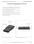
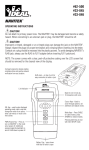
 Narrow linewidth DFB laser
Broadband Lithium Niobate modulator
High gain modulator driver module
Automatic Bias Control Circuit to ensure stable operation
Excellent eye diagram for error-free transmission
Connector choice: FC/APC, FC/UPC, SC/APC, SC/UPC, LC/APC, LC/UPC
Polarization Maintaining (PM) output available on 12.5Gb/s model
High reliability Telcordia-qualified components
Three year limited warrant
OptiLab, LLC undertakes continuous and intensive
product development to ensure its products perform at
the highest technical standards. As a result, the
specifications in this document are subject to change.
OptiLab, LLC
5110 N. 44th Street,
Suite 200L
Phoenix, AZ 85018
[email protected]
www.oequest.com
Tel.: (602) 343-1493
Fax: (602) 343-1489
1. User Safety
•
The LT-1550-12.5G emits high intensity invisible light from the
optical output receptacle. Avoid direct exposure to skin and eyes.
•
The equipment case is fully certified for EMS protection. The user
should never open the equipment case; any attempt will void the
warranty and may result in electric shock and EMS attacks to
equipment in the vicinity.
•
The user should avoid using any solvent or vaporizing chemical to
clean the equipment panel or case. It may result in damage to the
surface and internal circuits.
OptiLab, LLC undertakes continuous and intensive
product development to ensure its products perform at
the highest technical standards. As a result, the
specifications in this document are subject to change.
OptiLab, LLC
5110 N. 44th Street,
Suite 200L
Phoenix, AZ 85018
[email protected]
www.oequest.com
Tel.: (602) 343-1493
Fax: (602) 343-1489
2. Operation
2.1 Introduction
This section describes how to operate the LT-1550-12.5G Lightwave Transmitter
and discusses the location and function of the controls and connectors.
2.2 Initial Inspection
When you receive the LT-1550-12.5G, verify that the following items are included:
1.
2.
3.
4.
5.
6.
LT-1550-12.5G Lightwave Transmitter.
User’s Manual
RS232 Serial Direct Cable
Control Software Manual
Control Software CD Package
AC Power Cord
The LT-1550-12.5G was carefully inspected before it left the manufacturer. It
should be in proper working order upon receipt. You should, however, inspect the
unit for any damage that may have occurred in transit. If the shipping container or
the packing material is damaged, keep it until the contents of the shipment have
been checked to be free of mechanical and electrical damages. Notify Optilab, LLC
promptly if any notable damage is found.
OptiLab, LLC undertakes continuous and intensive
product development to ensure its products perform at
the highest technical standards. As a result, the
specifications in this document are subject to change.
OptiLab, LLC
5110 N. 44th Street,
Suite 200L
Phoenix, AZ 85018
[email protected]
www.oequest.com
Tel.: (602) 343-1493
Fax: (602) 343-1489
2.3 Controls
6
2
1
4
5
3
7
LT-1550-12.5G Front
Panel
Features
Function
1. Main Display
The LCD display shows the control parameters, warning messages and control
parameters of the LT-1550-12.5G unit.
2. Warning Indicators
These two indicators light up to warn when:
(1) The pump laser is ON and the driving value is greater than zero (Enable).
(2) The pump laser is overheated (Temp. Overheat).
3. Power Indicator
This indicator lights up when the power to the LT-1550-12.5G unit has been
turned on.
4. Select Button
Pressing the button selects and deselects the highlighted control parameter for
modification. The unit beeps once to acknowledge when the button is pressed.
5. Control Knob
The knob allows the user to select and modify the control parameters of the unit.
Turning the knob clockwise moves the selection cursor up or increases the
selected parameter. Turning the knob counter-clockwise moves the selection
cursor down or decreases the selected parameter.
6. Data Input SMA Connector
SMA connector that accepts the up to 1.0 V peak-to-peak RF modulation signal
with 50 input impedance. *
7. Optical Output Receptacle
This receptacle accepts the FC/APC fiber-optic connector for optical output. **
* This transmitter is an ESD-sensitive device. Proper procedures, including equipment grounding, wearing ESD
straps, and using ESD benches must be strictly followed.
** Note that proper cleaning and handling for the connectors is required to keep the transmitter performing
properly. A built-in optical isolator has been incorporated to protect the unit from optical feedback and to improve
stability.
OptiLab, LLC undertakes continuous and intensive
product development to ensure its products perform at
the highest technical standards. As a result, the
specifications in this document are subject to change.
OptiLab, LLC
5110 N. 44th Street,
Suite 200L
Phoenix, AZ 85018
[email protected]
www.oequest.com
Tel.: (602) 343-1493
Fax: (602) 343-1489
5
1
2
3
4
LT-1550-12.5G Rear
Panel
Features
Function
1. Nameplate
The nameplate records the equipment’s serial number.
2. AC Power Socket
The AC power socket is the input for the AC power source. A three-pin standard
power cord should be used to connect this equipment to any 110 or 220 V main
supply.
3. Fuse Socket
The fuse socket accepts a 5 x 20mm mini fuse. A Quick-acting fuse should be used
for maximum protection.
4. Main Switch
The main switch is the master AC power switch for the unit including the optical
output.
5. RS232 Female Socket
For remote control and monitoring, the user can plug-in the RS232 direct cable
provided, connecting the unit to a personal computer. For the control software,
please refer to the control software user guide.
2.4 Main Menu Screen
Upon powering up the LT-1550-12.5G unit, a logo lights up on the Main Display for
a few seconds while the unit initializes. After initialization, the Main Menu screen
will appear.
OptiLab, LLC undertakes continuous and intensive
product development to ensure its products perform at
the highest technical standards. As a result, the
specifications in this document are subject to change.
OptiLab, LLC
5110 N. 44th Street,
Suite 200L
Phoenix, AZ 85018
[email protected]
www.oequest.com
Tel.: (602) 343-1493
Fax: (602) 343-1489
2.4 Main Menu Screen (cont’d.)
There are four sub-menus that can be accessed from the Main Menu page:
Wavelength Setting Menu, Power Control Menu, Modulation & Bias Menu, and
Operation Status Menu. Not all the sub-menus are can be viewed on the Main
Display at the same time. To see the other sub-menus turn the knob to scroll the
page. To enter a sub-menu, turn the knob until the flashing cursor is next to the
name of the sub-menu, then press the Select button.
There are four major sub-menus can be accessed through the front panel and
control knob:
1.
2.
3.
4.
Wavelength Setting Menu
Power Control Menu
Modulator Bias Control Menu
Status Menu
The sub-menus of the LCD are shown below:
Within a sub-menu, all the parameters can be viewed by turning the knob to scroll
the page up or down. To change a parameter, turn the knob until the flashing
cursor is next to the parameter, then press the Select button.
2.4.1 Wavelength Setting
The Wavelength Setting Menu allows the user to select the optical output channel,
set the grid spacing, and configure the frequency for channel #1.
OptiLab, LLC undertakes continuous and intensive
product development to ensure its products perform at
the highest technical standards. As a result, the
specifications in this document are subject to change.
OptiLab, LLC
5110 N. 44th Street,
Suite 200L
Phoenix, AZ 85018
[email protected]
www.oequest.com
Tel.: (602) 343-1493
Fax: (602) 343-1489
2.4.1 Wavelength Setting (cont’d.)
Parameter
Function
Channel
Selects optical channel of grid that appears at output of transmitter.
Grid
Sets the grid spacing between optical channels.
Ch1 Freq Ctrl
Sets the frequency of the first optical channel in the grid.
Ch Freq Value
Displays frequency of optical channel currently selected.
<<Back>>
Exits sub-menu and returns to Main Menu.
Examples of the LCD screens are shown below:
2.4.2 Power Control
The Power Control Menu allows the user to set the optical output power of the
transmitter, enable or disable the optical output, and configure the dithering function
for the optical output.
Parameter
Function
Power
Sets optical output power level.
Status
Enables/Disables optical output of transmitter.
Dither FM Freq
Sets the dithering frequency.
Dither FM Amp
Sets the dithering amplitude.
Dither
Enables/Disables dithering of optical output.
<<Back>>
Exits sub-menu and returns to Main Menu.
OptiLab, LLC undertakes continuous and intensive
product development to ensure its products perform at
the highest technical standards. As a result, the
specifications in this document are subject to change.
OptiLab, LLC
5110 N. 44th Street,
Suite 200L
Phoenix, AZ 85018
[email protected]
www.oequest.com
Tel.: (602) 343-1493
Fax: (602) 343-1489
2.4.2 Power Control (cont’d.)
Examples of the LCD screens are shown below:
2.4.3 Modulation and Bias Control
The Modulation & Bias Menu allows the user to set the modulation voltage, enable
or disable the automatic bias control, or manually set the bias voltage.
Parameter
Function
Gain Ctrl
Sets gain level of RF power from RF driver amplifier into optical modulator.
Bias Pt
Sets bias mode to Q+, Q-, Max, Min.
ABC Reset
Resets automatic bias control function.
ABC Status
Selection of manual or automatic bias control.
Man Bias
Sets bias voltage to optical modulator manually, 0 to 15 VDC.
Bias Volt
Display the bias voltage that is being applied to the optical modulator, during
Automatic Bias Control mode
<<Back>>
Exits sub-menu and returns to Main Menu.
OptiLab, LLC undertakes continuous and intensive
product development to ensure its products perform at
the highest technical standards. As a result, the
specifications in this document are subject to change.
OptiLab, LLC
5110 N. 44th Street,
Suite 200L
Phoenix, AZ 85018
[email protected]
www.oequest.com
Tel.: (602) 343-1493
Fax: (602) 343-1489
2.4.3 Modulation and Bias Control (cont’d.)
Examples of the LCD screens are shown below:
2.4.4 Bias Control Modes
There are 4 different modes of bias that can be set up in the transmitter:
–
Q+ (Quadrature Positive)
The modulator is based at the Quadrature point of the Positive slope of
modulator transfer function.
–
Q- (Quadrature Negative)
The modulator is based at the Quadrature point of the Negative slope of
modulator transfer function.
OptiLab, LLC undertakes continuous and intensive
product development to ensure its products perform at
the highest technical standards. As a result, the
specifications in this document are subject to change.
OptiLab, LLC
5110 N. 44th Street,
Suite 200L
Phoenix, AZ 85018
[email protected]
www.oequest.com
Tel.: (602) 343-1493
Fax: (602) 343-1489
2.4.4 Bias Control Modes
–
Max (Maximum)
The modulator is based at the Maximum point of the modulator transfer
function.
–
Min (Minimum)
The modulator is based at the Minimum point of the modulator transfer
function.
Depending on the bias point selected, the output of the transmitter Eye Diagrams
can be very different.
The following are examples of the Eye Diagrams, modulated @ 10Gb/s:
Biased @ Negative Quadrature
Biased @ Positive Quadrature
OptiLab, LLC undertakes continuous and intensive
product development to ensure its products perform at
the highest technical standards. As a result, the
specifications in this document are subject to change.
OptiLab, LLC
5110 N. 44th Street,
Suite 200L
Phoenix, AZ 85018
[email protected]
www.oequest.com
Tel.: (602) 343-1493
Fax: (602) 343-1489
2.4.4 Bias Control Modes (cont’d.)
Biased @ Maximum
Biased @ Minimum
* Data input rate: 10Gb/s from Agilent BERT
** Eye diagram measured with Agilent 86100A Digital Communication Analyzer
2.4.5 Operation Status
The Operation Status Menu allows the user to read the current operational status of
the laser and transmitter, and configure the warning threshold levels.
OptiLab, LLC undertakes continuous and intensive
product development to ensure its products perform at
the highest technical standards. As a result, the
specifications in this document are subject to change.
OptiLab, LLC
5110 N. 44th Street,
Suite 200L
Phoenix, AZ 85018
[email protected]
www.oequest.com
Tel.: (602) 343-1493
Fax: (602) 343-1489
2.4.5 Operation Status (cont’d.)
Parameter
Function
Temp
Displays temperature of laser.
Cur
Displays current of laser
Power
Displays optical output power of laser.
O/P Power
Displays optical output power of transmitter.
Conf Pwr W Thres
Sets optical output power warning threshold for laser.
Fatal & Warning Power
Displays fatal and warning thresholds for optical output power.
Thermal
Displays fatal threshold for laser temperature.
Freq
Displays fatal threshold for optical channel frequency.
<<Back>>
Exits sub-menu and returns to Main Menu.
2.5 Operating Instructions
Start-up Procedure
1. Turn the main key switch clockwise to the On position to enable
electrical power to the unit. The power indicator will light up and the LCD
display will show a logo.
2. Wait for the LCD display to switch to the Main Menu screen.
3. Connect the optical output receptacle using FC/APC connectorized
patchcords to obtain the optical output.
4. Connect the Data input to the input source signal.
Verify Operation Procedure
1. Select the Power Control Menu and enable the laser. When the
laser is
enabled, a green LED will illuminate on the front panel.
OptiLab, LLC undertakes continuous and intensive
product development to ensure its products perform at
the highest technical standards. As a result, the
specifications in this document are subject to change.
OptiLab, LLC
5110 N. 44th Street,
Suite 200L
Phoenix, AZ 85018
[email protected]
www.oequest.com
Tel.: (602) 343-1493
Fax: (602) 343-1489
2.5 Operating Instructions (cont’d.)
Verify Operation Procedure (cont’d.)
LED
power
+5dbm.
2. The bias of the modulator should be set to the Q+ mode. A green
should be turned on in the front panel.
3. Connect the optical output to an optical power meter. The output
level of the transmitter should read between +3dBm to
4. Connect the Data input to the output of Pattern Generator. The
typical
setting of the Pattern Generator is shown below. (Data Rate
of 9.964 GHz,
Drive Voltage Vp-p of 0.328 Volt and Bias Voltage of -0.127
Volt)
5. Connect the optical output to an optical input of a high-speed
sampling
scope or digital communications analyzer, such as Tektronix
CSA8000B or
Agilent 86100B. The typical Eye Diagram should be shown as
below:
OptiLab, LLC undertakes continuous and intensive
product development to ensure its products perform at
the highest technical standards. As a result, the
specifications in this document are subject to change.
OptiLab, LLC
5110 N. 44th Street,
Suite 200L
Phoenix, AZ 85018
[email protected]
www.oequest.com
Tel.: (602) 343-1493
Fax: (602) 343-1489
2.5 Operating Instructions (cont’d.)
Patchcord Swapping Procedure
1. Select the Status parameter and change it to Disable.
2. Swap patchcords as desired. Only connect FC/APC connectorized
patchcords to the optical input/output receptacles.
3. Select the Status parameter and change it to Enable for optical
power.
Over-Temperature Procedure
1. When the Temp Overheat warning appears the optical output will
shutdown automatically and the system will freeze.
2. Turn the main key switch counter-clockwise to the Off position.
3. Restart the unit using the Start-up Procedure described above.
2.6 Warning Messages
There are two warning messages that may appear on the LCD screen: Temp.
WARNING and Temp. Overheat.
Temp. WARNING
When the laser temperature approaches the upper limit, the Temp.
WARNING message appears on the LCD screen to warn the user. The
system will continue to operate normally, as long as the temperature does
not exceed the limit.
Temp. Overheat
The Temp. Overheat message appears on the LCD screen when the
laser
temperature has exceeded the upper limit. The pump lasers
will shutdown
immediately and the system will freeze up. In such case, the
unit should be
switched off and restarted.
OptiLab, LLC undertakes continuous and intensive
product development to ensure its products perform at
the highest technical standards. As a result, the
specifications in this document are subject to change.
OptiLab, LLC
5110 N. 44th Street,
Suite 200L
Phoenix, AZ 85018
[email protected]
www.oequest.com
Tel.: (602) 343-1493
Fax: (602) 343-1489
2.7 PC Connection Mode
The unit begins the PC connection mode when the RS232 port is connected to
a PC, and the control software is initialized. In this mode, the parameter
information of the laser continues to be displayed, but there is no response to
the knob button on the front panel. The user can only control the unit through
the control software on the PC. Once the software program stops execution,
the unit will return to local control. If the RS232 direct cable is disconnected,
the unit will automatically restore to local control.
For detailed software control, please refer to the software control user guide.
OptiLab, LLC undertakes continuous and intensive
product development to ensure its products perform at
the highest technical standards. As a result, the
specifications in this document are subject to change.
OptiLab, LLC
5110 N. 44th Street,
Suite 200L
Phoenix, AZ 85018
[email protected]
www.oequest.com
Tel.: (602) 343-1493
Fax: (602) 343-1489
3. Troubleshooting
Symptom
Possible Cause and Solution
C: Laser power not turned up high enough.
S: Select Pwr parameter in Power Control Menu and increase until the optical
output power stops changing.
Optical output power not high
enough.
C: Optical input/output connectors dirty.
S: Disable optical output and clean optical connectors.
C: Optical output connector damaged.
S: Measure optical output power with power meter and compare with readout on
Main Display. Return to Optilab for repair if the difference is high and cannot be
corrected by cleaning the optical connectors.
C: Insufficient ventilation.
S: Place unit in well ventilated area or supply additional fans for ventilation.
Optical output power unstable.
C: Insufficient optical output isolation.
S: Connect isolator of corresponding wavelength to optical output connector.
C: Blown fuse.
S: Check fuse and replace if it has blown.
Unit does not power up.
C: Insufficient electrical voltage.
S: Check that the electrical supply is at least 110 VAC.
C: Power cord is loose.
S: Plug power cord is firmly into the unit.
Unit resets or blinks on and off.
C: Insufficient electrical voltage.
S: Check that the electrical supply is at least 110 VAC.
OptiLab, LLC undertakes continuous and intensive
product development to ensure its products perform at
the highest technical standards. As a result, the
specifications in this document are subject to change.
OptiLab, LLC
5110 N. 44th Street,
Suite 200L
Phoenix, AZ 85018
[email protected]
www.oequest.com
Tel.: (602) 343-1493
Fax: (602) 343-1489
4. Service and Support
4.1 Warranty
Optilab, LLC guarantees this LT-1550-12.5G unit to be free of defects for 1 year
from the date of shipment. This term includes a 12-month guarantee for the tunable
laser module and 24 months for other electronics and mechanical parts. The
guarantee does not cover any damages resulting from the misuse or improper
handling of the equipment, or any incidental or consequential loss. Note that the
warranty will be void upon any attempt to open or to fix the equipment by the user
without prior approval of Optilab, LLC.
4.2 Service and Calibration
Your LT-1550-12.5G unit has been designed to provide years of trouble-free
operation. No internal maintenance is required provided that the equipment is
properly handled, operated and kept away from contamination. For any questions
regarding the operation and performance of the unit, please contact Optilab, LLC.
Optilab, LLC
5110 N. 44th Street
Suite 200L
Phoenix, AZ 85018
USA
Tel: (602) 343-1496
Fax: (602) 343-1489
Email: [email protected]
OptiLab, LLC undertakes continuous and intensive
product development to ensure its products perform at
the highest technical standards. As a result, the
specifications in this document are subject to change.
OptiLab, LLC
5110 N. 44th Street,
Suite 200L
Phoenix, AZ 85018
[email protected]
www.oequest.com
Tel.: (602) 343-1493
Fax: (602) 343-1489
4.3 Care of Fiber Optic Connectors
Damage to fiber-optic connectors account for more than 70 percent of equipment
performance degradation. To avoid such damage, the user should follow the
procedures below to keep the connectors clean:
1. Clean the connector with optical tissue soaked with alcohol that is at least 90%
pure.
2. Clean the connector again with dry optical tissue.
Reasons:
1. Cleaning the connector with wet optical tissue removes dust particles, oil and
contaminants that may damage or blot the surface of the optical fiber during
connection.
2. Cleaning the connector with dry optical tissue removes residual alcohol that may
be ignited by optical emission.
OptiLab, LLC undertakes continuous and intensive
product development to ensure its products perform at
the highest technical standards. As a result, the
specifications in this document are subject to change.
OptiLab, LLC
5110 N. 44th Street,
Suite 200L
Phoenix, AZ 85018
[email protected]
www.oequest.com
Tel.: (602) 343-1493
Fax: (602) 343-1489