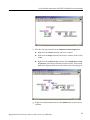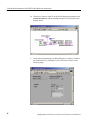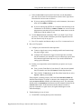
1
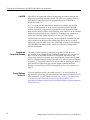
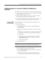
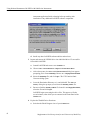
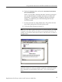
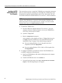
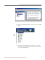
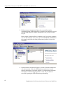
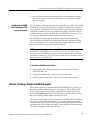
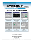
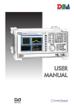
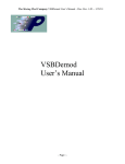
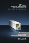
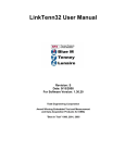
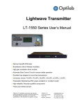
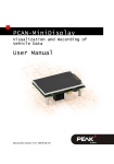
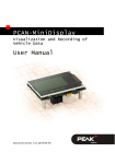
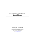
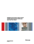
Supplement CSA8000 & TDS8000 Instruments CSA8000B & TDS8000B Instruments Using National Instruments LabVIEW This document applies to software version 1.3 and above. www.tektronix.com Copyright © Tektronix, Inc. All rights reserved. Tektronix products are covered by U.S. and foreign patents, issued and pending. Information in this publication supercedes that in all previously published material. Specifications and price change privileges reserved. Tektronix, Inc., P.O. Box 500, Beaverton, OR 97077 TEKTRONIX and TEK are registered trademarks of Tektronix, Inc. FrameScan is a trademark of Tektronix, Inc. Table of Contents Preface . . . . . . . . . . . . . . . . . . . . . . . . . . . . . . . . . . . . . . . . . . . . . . . . . . . ii Contacting Tektronix . . . . . . . . . . . . . . . . . . . . . . . . . . . . . . . . . . . . . . . . . . . . . ii Using National Instruments LabVIEW . . . . . . . . . . . . . . . . . . . . . . . . 1 Overviews: . . . . . . . . . . . . . . . . . . . . . . . . . . . . . . . . . . . . . . . . . . . . . . . . . . . . . TekVISA and the Plug&Play Driver . . . . . . . . . . . . . . . . . . . . . . . . . . . . . . LabVIEW . . . . . . . . . . . . . . . . . . . . . . . . . . . . . . . . . . . . . . . . . . . . . . . . . . Analysis and Connectivity Software . . . . . . . . . . . . . . . . . . . . . . . . . . . . . . Product Software Version 1.3 . . . . . . . . . . . . . . . . . . . . . . . . . . . . . . . . . . . LabVIEW Installations for Use with the CSA8000 and TDS8000 Series Instruments . . . . . . . . . . . . . . . . . . . . . . . . . . . . . . . . . . . . . . . . . . . . . . . . . . . . Installing LabView on your Instrument . . . . . . . . . . . . . . . . . . . . . . . . . . . Installing LabVIEW VXIPlug&Play driver on a computer . . . . . . . . . . . . Installing the LabVIEW Run Time Engine (RTE) on your Instrument . . . Tutorial: Creating a Simple LabVIEW program . . . . . . . . . . . . . . . . . . . . . . . . For More Information . . . . . . . . . . . . . . . . . . . . . . . . . . . . . . . . . . . . . . . . . . . . . 1 1 2 2 2 Supplement to Oscilloscope Analysis and Connectivity Made Easy 3 3 6 9 9 15 i Preface This document supplements the information found in the manual Oscilloscope Analysis and Connectivity Made Easy, that ships with certain Tektronix products. Contacting Tektronix Phone 1-800-833-9200* Address Tektronix, Inc. Department or name (if known) 14200 SW Karl Braun Drive P.O. Box 500 Beaverton, OR 97077 USA Web site www.tektronix.com Sales support 1-800-833-9200, select option 1* Service support 1-800-833-9200, select option 2* Technical support Email: [email protected] 1-800-833-9200, select option 3* 6:00 a.m. - 5:00 p.m. Pacific time * ii This phone number is toll free in North America. After office hours, please leave a voice mail message. Outside North America, contact a Tektronix sales office or distributor; see the Tektronix web site for a list of offices. Supplement to Oscilloscope Analysis and Connectivity Made Easy Using National Instruments LabVIEW with 8000 Series Instruments With the introduction of the Version 1.3 Product-software Upgrade for the CSA8000 Communication Signal Analyzers and TDS8000 Digital Sampling Oscilloscopes, you now have several new options for controlling these instruments using off-the-shelf software-development and data-analysis tools. This document: H focuses on the LabVIEW (Laboratory Virtual Instrument Engineering Workbench) software from National Instruments. H describes how to tap the power of this popular programming language to control the CSA8000 and TDS8000 instruments for enhanced productivity and analysis. The following topics are covered: H Overviews of TekVISA, VXI Plug & Play drivers, LabVIEW, the Tektronix Analysis and Connectivity Software (which comes with version 1.3 product software) H Three installation scenarios of LabVIEW for use with CSA8000 and TDS8000 application software H Creating and running a simple LabVIEW program Overviews: TekVISA and the VXI Plug & Play Driver, LabVIEW, and the Tektronix Analysis and Connectivity Software TekVISA and the Plug&Play Driver TekVISA is a library of industry-standard compliant software components, organized according to the standard VISA (Virtual Instrument Software Architecture) model established by the VXIplug&play Systems Alliance. TekVISA allows third party software applications to communicate directly with the instrument application over the instrument PCI bus instruments, eliminating the need for an external computer. After the VXIplug&play driver is imported into LabVIEW, the user will have access to a large collection of high level Virtual Instruments (VIs) that greatly simplify all aspects of programming the instrument. Tektronix supplies TekVISA and the VXIplug&play driver with our version 1.3 instrument application software. Supplement to Oscilloscope Analysis and Connectivity Made Easy 1 Using National Instruments LabVIEW with 8000 Series Instruments LabVIEW LabVIEW is an engineering software development environment based on the graphical programming language called G. LabVIEW uses graphical symbols rather than text language to describe programming actions. LabVIEW is designed to build a VI. A VI is a virtual test and measurement instrument (a software program) that executes on the instrument or on an external computer from the LabVIEW software. LabVIEW is integrated for communication with hardware through built-in VISA resource libraries. With TekVISA, a LabVIEW VI can be executed directly from the desktop of your CSA8000 or TDS8000 Series instrument to control the instrument, gather and analyze its data, and create reports. LabVIEW can also compile completed VIs into LabVIEW executable files that can be distributed to other users not running LabVIEW software. All that is required for a non-LabVIEW user to run a LabVIEW executable is to install the LabVIEW Run Time Engine (RTE), which is provided free of charge from National Instruments. Analysis and Connectivity Software The Analysis and Connectivity Software (except the VXI PnP Driver) is pre-installed on the CSA8000B and TDS8000B instruments and is included in the 1.3 release of the product software CD. By default, the Analysis and Connectivity Software is installed when reinstalling the product software from the CD, or when installing from the CD as part of a Customer Software Upgrade to release 1.3. The product-software CD also provides for installing the Analysis and Connectivity Software on any personal computer running Microsoft Windows (see Installing LabVIEW VXIPlug&Play Drivers on a Computer on page 6). Product Software Version 1.3 If you are running an earlier version than version 1.3, be sure to perform an upgrade before proceeding with the installations and instructions that follow. For more information visit the Tektronix web site: http://www.tek.com/Measurement/ cgi-bin/framed.pl?Document=/Measurement/scopes/index/prodindex_sampling.html?wt=255&link=/Measurement/scopes/index/prodindex_sampling.html&Fram eSet=oscilloscopes 2 Supplement to Oscilloscope Analysis and Connectivity Made Easy Using National Instruments LabVIEW with 8000 Series Instruments LabVIEW Installations for Use with the CSA8000 and TDS8000 Series Instruments The following section discusses the three most common LabVIEW installations: Installing LabVIEW on your Instrument H First time installation of LabVIEW on an instrument running the CSA8000& TDS8000 application software, version 1.3. H Installing LabVIEW VXIplug&play drivers on a computer workstation in order to control the instrument over the GPIB or network. H Installing the LabVIEW Run Time Engine (RTE) on the instrument in order to run pre-built LabVIEW executable files without using LabVIEW. This installation requires that the instrument application software be at least version 1.3 or greater. 1. Install the VXIPnP Driver: a. Open Windows Explorer and open folder: C:\Program Files\Tektronix\VXIPNPInstall. b. Double-click on setup.exe in this folder and it will install the VXI PnP driver. After installation, a VXIpnp folder will be created. In the VXIpnp folder, you will find the following items that provide additional information: H Tktds8k Help H Tktds8k Samples (these samples do not pertain to LabVIEW; for information on where to get LabVIEW samples see Additional LabVIEW Support below). H Uninstall Instrument Driver 2. Install LabVIEW Software: NOTE. The Release notes that accompany the Product Software Release 1.3 state “Warning: Do not install any software component that includes a GPIB device driver..” This warning can be safely disregarded for the installation of LabVIEW. a. Run the LabVIEW installer from the LabVIEW CD. b. Choose Complete Installation to ensure that all of the necessary VISA resources will be installed. c. Re-boot the instrument after this complete installation. During the re-boot, the following message should pop up. Click OK and let the Supplement to Oscilloscope Analysis and Connectivity Made Easy 3 Using National Instruments LabVIEW with 8000 Series Instruments instrument application finish re-booting before proceeding with installation of any additional LabVIEW software components. d. Install any other LabVIEW software add-ins and tool sets. 3. Import and convert the VXIPnP driver into individual driver VIs accessible from within LabVIEW: a. Launch LabVIEW and create a new Untitled 1.vi. b. Choose Tools > Instrumentation > Import CVI Instrument Drive. c. After a short pause, the Select a CVI Function Panel dialog box appears prompting you to locate tktds8k.fp. Browse to c:VXIpnp\Win95\Tktds8k. d. Select the tktds8k.fp file, and click Open. The CVI Function Panel Converter dialog opens. e. Leave the Destination Directory as is, and click OK. The Select A Library dialog box prompts you to locate the tktds8k_32.DLL file. f. Browse to find the tktds8k_32.DLL file located in C:VXIpnp\Win95\Bin\, select the file and click Open. LabVIEW begins converting the driver files. This process will take several minutes, after which you are returned to the Front Panel of the Untitled 1.vi. 4. Explore the Tktds8k Driver Functions: a. Switch to the Block Diagram view of your Untitled 1.vi. 4 Supplement to Oscilloscope Analysis and Connectivity Made Easy Using National Instruments LabVIEW with 8000 Series Instruments b. Display the Functions palette, and open the Instrument I/O\Instrument Drivers\Tktds8k Folder. Inside is a list of folders containing individual VIs that can be dropped onto your Block Diagram to configure and control your 8000 series instrument(s). A large number of plug&play functions, grouped by category, are available for you to select and incorporate into your LabVIEW program. c. To select one of the VIs, simply double-click it. The pointer tool turns into a hand to indicate that a selection has been made. d. Click on the Block Diagram to drop the VI. NOTE. To get the name of a particular function on a Block Diagram, press Ctrl-H to display context help, and hover the mouse over the function in question. For example, you can obtain context help for each Vi in the PnP driver, as shown in the figure below. NOTE. If LabVIEW was installed on the instrument prior to upgrading the scope application software to version 1.3, all that is required is to install the VXIPnP driver and import it into LabVIEW. Follow steps 1, 3 & 4 in the procedure above. Supplement to Oscilloscope Analysis and Connectivity Made Easy 5 Using National Instruments LabVIEW with 8000 Series Instruments Installing LabVIEW VXIPlug&Play Drivers on a Computer This section discusses how to install the VXIPnP driver to control the instrument from an external computer workstation over the GPIB. The VXIPnP driver may be installed on computers running Windows 98, NT 4.0, 2000, and/or XP. You will need the 8000 Series Product-Software CD, Version 1.3, for this installation. NOTE. For this installation, it is not necessary to install TekVISA on your computer. The VXIPnP driver is layered to work with either TekVISA or the National Instruments NI VISA implementation. NI VISA is normally installed automatically as part of a Complete Install of LabVIEW. 1. To install the VXIPnP driver: a. Insert the 8000-Series Product-Software CD, Version 1.3, into your computer, and open a Windows Explorer view to your CDROM drive. You will see several top-level folders. b. Open the VXIpnp folder. c. Run the VxiPnp\setup.exe program. After installation, your computer will have a VXIpnp folder located at C:VXIpnp. Import the VXIPnP driver into LabVIEW following the instructions in step 3 on page 4. Note the following exceptions: H If you are running Windows 95 or 98, the path to the driver components will be C:VXIpnp\Win95\… H If you are running Windows NT 4.0, 2000, or XP, the path will be C:VXIpnp\WINNT\… 2. To configure LabVIEW to communicate with the CSA/TDS8000 Series overGPIB, complete the following steps: a. Install your GPIB hardware and connect cabling between the computer and the instrument. b. Launch LabVIEW and create a new Untitled 1.vi. c. From the Front Panel menu select Tools > Measurement & Automation Explorer. The following dialog box will appear: 6 Supplement to Oscilloscope Analysis and Connectivity Made Easy Using National Instruments LabVIEW with 8000 Series Instruments d. Right Click the Devices & Interfaces Folder Icon and create a new GPIB Interface. GPIB Interface e. Expand the Devices & Interfaces folder. You should now see a GPIB folder, shown as selected in the figure below. Right click this folder and select Scan for GPIB Instruments. Supplement to Oscilloscope Analysis and Connectivity Made Easy 7 Using National Instruments LabVIEW with 8000 Series Instruments 3. If Measurement & Automation Explorer has successfully found the instrument, note the GPIB address that’s assigned to the instrument. You will need the GPIB address to complete the tutorial Creating a Simple LabVIEW Program. In the example figure that follows, the number is 0. If you wish to communicate with the instrument at this time, right click InstrumentX (Instrument0 in this example) and follow the dialog instructions to perform a query to the instrument. 4. If Measurement & Automation Explorer is unable to find and communicate with the instrument, follow the GPIB hardware manufacturers trouble shooting instructions to remedy the problem. Use Measurement & Automation Explorer troubleshooting suggestions as well, and you should be successful in getting the GPIB connection up and running. 8 Supplement to Oscilloscope Analysis and Connectivity Made Easy Using National Instruments LabVIEW with 8000 Series Instruments 5. Once the Measurement & Automation Explorer can communicate with the instrument, you may continue with the tutorial Creating a Simple LabVIEW Program on page 9. Installing the LabVIEW Run Time Engine (RTE) on your Instrument This installation enables the instrument to run LabVIEW executable files without installing the entire LabVIEW software. LabVIEW executable files require the user to have the LabVIEW Run Time Engine (RTE) installed on their computer (LabVIEW executable files will run on machines that have LabVIEW software installed without the need for the RTE). The LabVIEW RTE (currently version 6.0.2) may be downloaded from the National Instruments Web site. The LabVIEW executable files are compiled using a National Instruments software add-on for LabVIEW called Application Builder. Application Builder converts LabVIEW VIs into compiled executable programs that can be distributed to non-LabVIEW users to run on their computers. NOTE. Application Builder can create LabVIEW executable files that will automatically install RTE 6.0.2 as an option for the user. This feature makes it very convenient for LabVIEW developers to develop and distribute stand-alone LabVIEW executable files. The LabVIEW executable files downloadable from the Tektronix do not install RTE 6.0.2. To install the LabVIEW Run-time Engine: 1. Download the self-extracting executable (*.exe) file from the National Instruments Web site. 2. Copy the downloaded file to a directory on your instrument. 3. Double-click the executable file, and follow the instructions on screen. Tutorial: Creating a Simple LabVIEW program This tutorial acquaints you with the LabVIEW Tktds8k drivers by guiding you through the creation of and running of a very simple VI. The VI that you will create simply initializes the instrument, implements the default setup (just as pressing the Default Setup button on the front of the instrument does), and then turns on a sampling-module channel selected by the user. Successfully completing this tutorial ensures that LabVIEW and the Plug&Play drivers are properly installed and that the VI is communicating properly with instrument. You can the use the VI that you created during the tutorial for further experimentation. This VI and other sample VIs are available for download from the Tektronix Sampling Oscilloscope Web site. Supplement to Oscilloscope Analysis and Connectivity Made Easy 9 Using National Instruments LabVIEW with 8000 Series Instruments NOTE. This tutorial is valid for operating LabVIEW directly on the instrument, or for running LabVIEW on a computer connected to the instrument over the GPIB. Note that the GPIB instrument number listed in the Resource Name control will differ depending on which of these operation methods is used. 1. Create the LabVIEW program: a. Launch LabVIEW and create a new Untitled 1.vi. Go to the Block diagram view. b. Make the Tools palette and Functions palette visible. c. Select Tools > Options, select the check box next to Show subVI names when dropped, and click OK. d. Go to the Functions palette, and open the Instrument I/O > Instrument Drivers > Tktds8k Folder. Locate and drop the following VIs onto your block diagram: H tktds8k Initialize.vi (Tktds8k Folder) H tktds8k Set Channel Displayed.vi (Vertical Folder > Configure Functions) H tktds8k Start or Stop Acquisitions.vi (Acquisition Folder > Configure Functions) H tktds8k Close.vi (Tktds8k Folder) Select each of the VIs in turn by simply double-clicking it in the functions palette. The pointer tool turns into a hand to indicate that a selection has been made. Click on the Block Diagram to drop the VI. Continue until you have dropped all four VIs on the Block Diagram. e. Select the Wiring Tool, and wire the following terminals on the tktds8k Initialize.vi: H Right-click the resource name terminal, and create a control by selecting create > control. H Right-click the ID Query terminal, and create a Boolean constant set to true. H Right-click the Reset Device terminal, and create a Boolean constant set to true. H Right-click the Instrument Handle Out terminal, and create an indicator. Your block diagram should now look similar to the figure that follows. 10 Supplement to Oscilloscope Analysis and Connectivity Made Easy Using National Instruments LabVIEW with 8000 Series Instruments f. Wire the following terminals on the tktds8k Set Channel Displayed.vi: H Right-click the channel terminal, and create a control. H Right-click the display terminal, and create a constant. Set this value to ON. H Right-click the acquisition state terminal of the tktds8k Start or Stop Acquisitions.vi, and create a Boolean constant. Set this value to true. Your block diagram should now look similar to the following figure: g. Right-click the Error Out terminal of the tktds8k Close.vi, and create an indicator. Supplement to Oscilloscope Analysis and Connectivity Made Easy 11 Using National Instruments LabVIEW with 8000 Series Instruments h. Thread wires between each VI on the Block Diagram that pertains to the instrument handle out and error in/out terminals as shown on the block diagram below: i. 12 At this point, programming your Block Diagram is complete. Switch to the Front Panel view, and organize your Front Panel as shown in the following figure. Supplement to Oscilloscope Analysis and Connectivity Made Easy Using National Instruments LabVIEW with 8000 Series Instruments j. In the resource name control on the Front Panel, use the Text Tool to enter the resource name for the instrument as shown in the figure above. Determine the resource name as follows: H If you are running LabVIEW directly on the instrument, the resource name will be GPIB8::1::INSTR. H If you are running LabVIEW from a computer and connecting to the instrument over the GPIB, try GPIB0::1::INSTR. You can also use the Measurement & Automation Explorer under the Tools menu to scan the GPIB bus to find the address to use. k. Use the Show Error List command (CTRL--L) to check if your VI has any errors. If it does, double check that your block diagram looks like the one shown in step h, on page 12. l. Your VI is complete and almost ready to run. Give it a name and save it. 2. Run your VI program: a. Configure your instrument for data acquisition: H Connect a signal source to any sampling module and connect/setup the proper trigger source. H Configure the instrument to trigger on and acquire the waveform. See the instrument user manual or access its online help system from the instrument application help menu if you need information for setting up the instrument. b. Perform a test acquisition on the channel that you plan to use in your demo VI. H First, go to the Front Panel of your demo VI, and select the channel that you intend to use from the Channel Control drop-down list. H Then click the VI Run button on the Front Panel menu bar (or select Operate > Run or press Ctrl-R). If the program is working properly, the Front Panel Instrument handle out indicator should display a response as shown in the example above, and the error out cluster indicator should not be indicating an error. The instrument should perform a Default Reset and then activate the channel indicated in the Channel Select control. If the instrument and the channel selected are properly connected to a signal source, the signal should appear on the instrument display. 3. Troubleshooting in case of errors: a. If LabVIEW is running directly on the instrument: Supplement to Oscilloscope Analysis and Connectivity Made Easy 13 Using National Instruments LabVIEW with 8000 Series Instruments H Check to see that the Instrument handle out indicator is showing a valid response similar to the example front panel above. H Check to see if the error indicator showing an error. If so, right click on the code indicator to get details on the error. H Verify that the Resource name has been entered correctly. NOTE. When running LabVIEW directly on the instrument, the Measurement & Automation Explorer will not work for troubleshooting virtual GPIB errors because TekVISA provides a modified implementation of the NI 488 GPIB driver. b. If running LabVIEW on an external computer: H Review the steps presented in Installing LabVIEW VXIPlug&Play Drivers on a Computer on page 6. Try to use the suggestions provided to resolve any GPIB communication problems. H Check to see that the Instrument handle out indicator is showing a valid response similar to the example front panel above. H Is the error indicator showing an error. Right click on the code indicator to get details on the error. H Verify that the Resource name has been entered correctly. For More Information Please visit our Website at www.tektronix.com for more information and additional LabVIEW resources, including TDS8000 and CSA8000 demonstration VIs and programming tips. 14 Supplement to Oscilloscope Analysis and Connectivity Made Easy