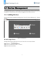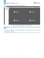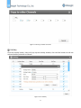
1
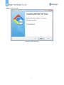
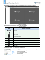
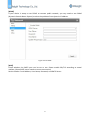
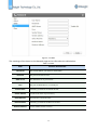
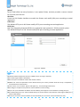
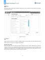
Central Management System User Manual Version 1.01 Copyright Statement This manual may not be reproduced in any form or by any means to create any derivative such as translation, transformation, or adaptation without the prior written permission of Milesight Technology Co., Ltd(Hereinafter referred to as Milesight). Milesight reserves the right to change this manual and the specifications without prior notice. The latest specifications and user documentation for all Milesight products are available on our official website www.milesight.com. Table of Contents Chapter 1 Introduction............................................................................................... 2 1.1 Introduction...................................................................................................................................................3 1.2 Key Features.................................................................................................................................................. 3 1.3 System Requirements................................................................................................................................... 3 Chapter 2 Installation.................................................................................................4 2.1 Installation Guide..........................................................................................................................................5 2.2 Log In/Out......................................................................................................................................................8 2.2.1 Log in.....................................................................................................................................................8 2.2.2 Log out................................................................................................................................................ 10 Chapter 3 Manage.................................................................................................... 11 3.1 Device Management...................................................................................................................................12 3.1.1 Adding Device..................................................................................................................................... 12 3.1.2 Removing or Log Out the Device........................................................................................................15 3.1.3 Log Out the Added Device..................................................................................................................16 3.1.4 Edit Device.......................................................................................................................................... 18 3.2 Device Config...............................................................................................................................................19 3.2.1 NVR..................................................................................................................................................... 19 3.2.2 Camera................................................................................................................................................ 33 3.3 User..............................................................................................................................................................48 Chapter 4 View......................................................................................................... 49 4.1 Live View......................................................................................................................................................50 4.1.1 How to Connect to Device..................................................................................................................51 4.1.2 Settings of Display the Live View........................................................................................................53 4.2 Playback.......................................................................................................................................................56 Chapter 5 Tools......................................................................................................... 57 5.1 E-Map...........................................................................................................................................................58 5.2 Log................................................................................................................................................................59 Chapter 6 Service......................................................................................................60 6.1 Service......................................................................................................................................................... 61 1 Chapter 1 Introduction Key Features System Requirements 2 1.1 Introduction The Milesight Central Management System(hereinafter referred to as CMS) software works to give you access and control of your Milesight High Definition Surveillance System. The Milesight CMS provides multiple operating functionalities, including live view, PTZ control, video playback, motion detection, alarm receiving, log and so on. This user manual describes the function, configuration and operation steps of CMS. To ensure the proper usage and stability of the CMS, please refer to the contents below and read the manual carefully before operation. The latest version of the software will be available on our official website. Please check our official website www.milesight.com for upgrading. 1.2 Key Features Support NVR as well as camera Support 1/ 4/ 8/ 9/ 16/ 36/ 64 channels playing synchronously Full screen for single or multiple channels H.265/H.264/MJPEG/MPEG-4 video compression Support dual-stream Support multiple PTZ control protocols Support custom time length for schedule record Motion detection, alarm recording and image capture function Easy to install and use 1.3 System Requirements OS: Windows XP/7/8/Vista/Server 2000/Server 2008 CPU: 2.4GHZ or faster Memory: 2G MB or more Graphic memory: 1G or more Internet protocol: TCP/IP 3 Chapter 2 Installation Installation Guide Log In/Out 4 2.1 Installation Guide Run the installation file and install the programs on your computer by following the on-screen instructions. After finishing installation, you will find the programs on the start menu or on the desktop. Step1: Click the installation file to install; Figure 2-1-1 Start Setup 5 Step2: Choose the folder in which to install Milesight CMS; Figure 2-1-2 Choose File Path Step3: Choose Start Menu Folder for the Milesight CMS; Figure 2-1-3 Choose the Start Menu 6 Step4: Finish the Setup: Figure 2-1-4 Finish the Setup 7 2.2 Log In/Out 2.2.1 Log in Click the icon to start the software, then choose the user and enter the password, the default account Username is: admin; Password is: password. You can check the checkbox to remember the password. Figure 2-2-1 Log In 8 After logging in the system, you can see the first page is the Live View page as follows: Figure 2-2-2 Live View And the meanings of the icons on the top-right are as follows: Table 2-2-1 Live View Item Function Introduction User name Click the button to lock the software, and it need to enter the password to unclock Menu button Minimize the interface Restore Down the interface Maxmize the interface Close the software To check the hidden pages when the windows is too small to show all the open pages Click the Menu button , the interface is as followed: Configuration Language , the live view record and snapshot file path setting View Adjust the windows to meet your need About Information of the CMS Log out Log out of the current account Exit Close the software 9 2.2.2 Log out Click →[Log out] to exit the current account, or click exit the CMS. Figure 2-2-3 Log Out Note Password is necessary for logging out. 10 → [Exit] or click Close button to Chapter 3 Manage Device Management Device Config User 11 3.1 Device Management The Milesight CMS supports to add Milesight cameras and NVRs to get an efficient and convenient management. The devices also can be removed or logged out of the CMS at any time. 3.1.1 Adding Devices There are two measures available for adding devices. First of all, click the Add button [+] →[Device Manage]. Figure 3-1-1 Adding Device Add a Single Device Milesight CMS provides to add device one by one. Please refer to the steps as follows: Step1: Click the button; Step2: Select the device type, “NVR” or “Camera”; Step3: Enter device information; 12 Figure 3-1-2 Add Device Manually The meanings of the items on the page can be referred to the table 3-1-1. Table 3-1-1 Add Device Manually Item Device Name IP Address Port User Name Password Transport Protocol Stream Mode Function Introduction Name of the device The IP address of the device The port of the device, the default NVR port is 1100 and the Camera’s is 80 The user name of the device, “admin” for the default Enter the password for the account of the device, the default password is “123456” for NVR while “ms1234” for Camera TCP and UDP are available There are three options, “Auto”, “Primary Stream” and “Secondary Stream” Once the device has been added successfully, there will pop up a window as follows: Figure 3-1-3 Add Device Successfully 13 Search Milesight CMS Supports to search devices automatically in the same network and add group devices with the same username and password. Please refer to the steps as follows: Step1: Click the button to search the Milesight devices in the same network; Step2: Select the devices; Step3: Enter the username and password of the selected devices, “admin” and “password” for the default username and password; Step4: Click button, then there will pop up a windows to remind you whether the devices are added successfully or not. Step5: Click the [OK] button; Step6: Click [Refresh] button to refresh the status of the added devices. Figure 3-1-4 Add Group Device Note Clicking the button can help the software to refresh the status of the added devices. Click the [No.] button can select all devices which were found; The devices found can be ranked by their IP, Port, Type, MAC, SN, Model when you click the corresponding button. The default password for Milesight camera is “ms1234” while the one for Milesight NVR is “123456”; Up to 50 devices can be added; 14 3.1.2 Remove or Log Out the Device Milesight CMS provides to remove the added device for group or single. First of all, enter the [Device Manage] page and do the steps as follows: Remove a Single Device The steps to remove a Single device are as follows: Step1: Click the button followed by the selected device; Step2: Click the [OK] to remove the device or [Cancel] button to cancel the action when the window pops up; Figure 3-1-5 Removing a single Device Remove Group Devices The steps to remove the devices for a group are as follows: Step1: Click the [No.] button to select all the added devices or check the checkbox to select several devices; Step2: Click the to remove the selected devices; Step3: Click the [OK] to remove the devices or [Cancel] button to cancel the action when the window pops up; 15 Figure 3-1-6 Remove Group Device 3.1.3 Log Out the Added Device You can log out the added device for a moment rather than to remove the device in case that the device will be used again one day. Logging out device can be understood as disabling the device in case it can be enabled one day. You can Click the button to log out the device, and the icon will turn into Figure 3-1-7 Log Out the Added Device on Device Management Page 16 ; Or right-click the selected device and choose the [Log out]. Figure 3-1-8 Log Out the Added Device on Live View Page Note You can click the button on Device Management page or right-click the device on Live View page and choose [Log in] to log in again. 17 3.1.4 Edit Device Click the Edit button to edit the added device. Except the Device Type and IP address, the other parameters can be edited. The interface is as followed: Figure 3-1-9 Edit Device The meanings of parameters can be referred to the table 3-1-1. Here will not repeat again. 18 3.2 Device Config Device Config provides Channels, Record and System three parts for NVR while Video, Event, Record and System four parts for Camera to set the devices. 3.2.1 NVR The NVR Configuration page is as follows: Figure 3-2-1 NVR Page 3.2.1.1 Channels Channel Channels management provides searching, adding, editing, deleting channels function. As for searching and deleting channels, please refer to the Chapter III Device Management 3.1 Adding Device, here will not repeat again. 19 Figure 3-2-2 Channels Management [Add Channel] The main difference between adding the cameras which found by the CMS and adding cameras manually is that adding cameras manually can add other brands’ cameras via ONVIF and RTSP protocol. Figure 3-2-3 Add Channel 20 ONVIF:Which supports ONVIF protocol; RTSP: Primary: rtsp://IP:Port/main Secondary: rtsp://IP:Port/sub (The port for RTSP protocol is 554 for default.) Milesight is only for the Milesight products. [Edit Channel] Click the Edit button , there will pop up the edit window as follows: Figure 3-2-4 Edit Channel The parameters are the same as Adding Manually. You can edit the channel when adding it firstly. Here will not repeat the steps again. 3.2.1.2 Record Schedule Click the Schedule button, the setting window will pop up as follows: 21 Figure 3-2-5 Schedule The meanings of the items of Schedule page can be referred to the table 3-2-1 below: Table 3-2-1 Schedule Item Channel Post Record Function Introduction Select the channel to set Enable or disable the Post Record function Duration Time There are several options to meet your need Audio Record Enable or disable the Audio Record Record Stream Type Main and Sub stream are available After finishing the settings, you can click the Copy button other channels. Click the Apply button to copy the settings to the to apply your settings to the CMS software. 22 Figure 3-2-6 Copy to Other Channels Holiday Click the Holiday button, there will pop up the Holiday window, click the Edit button to edit the selected holiday schedule as follows: Figure 3-2-7 Holiday 23 Disk Management Click the Dish Management to manage the disk, as the window shows, you can check the disk status and format the disk. You can draw the blue bar to get more information about the disk. Figure 3-2-8 Disk Management 24 3.2.1.3 System There are five parts in the System pages: General, Network, User, Status, Maintenance. Here we will introduce them in more details. General Click the General button , there will pop up the windows as follows: Figure 3-2-9 General You can edit the device name and ID for your own, and choose the right time zone and whether enable the Daylight Saving Time or not. It also supports to sync date and time with NTP or set the time manually. After finishing the settings, click the Apply button to save and apply the settings to the CMS. Network In the Network part, you can use several network functions, such as PPPoE, DDNS, and Mail etc. [Basic] Basic configuration includes working mode, IP Address, NetMask, Gateway, MTU, DNS server, etc. 25 Figure 3-2-10 Basic [PPPoE] Check the PPPoE checkbox to enable the feature, and then input user name, password for PPPoE access. Figure 3-2-11 PPPoE 26 [DDNS] If your device is setup to use PPPoE to connect public network, you may need to use DDNS (Dynamic Domain Name System) to solve the problems from dynamic IP address. Figure 3-2-12 DDNS [Mail] Check whether the SMTP port can be set or not. Please enable SSL/TLS according to actual mailbox. (Some SMTP server needs to secure connection) Set the Sender E-mail Address, User Name, Password, and SMTP Server: 27 Figure 3-2-13 Mail The meanings of the items on the Network page can be referred to the table below: Table 3-2-2 Mail Item User Name Password SMTP Server Function Introduction The E-mail address you choose to send emails The password of the E-mail The SMTP Server of your E-mail Port The port of SMTP Server, it’s usually 25 Sender Name Named by yourself for the Sender E-mail Sender Address It must be the same as [User name] Select Receiver You can have 3 receivers once Receiver Name Named by yourself for the Receiver E-mail Receiver Address E-mail Address for the receivers 28 [More] Secure Shell (SSH) has many functions; it can replace Telnet, and also provides a secure channel for FTP, POP, even for PPP. SSH Port: Check the SSH Enable checkbox to enable the feature and modify SSH ports according to actual application. HTTP Port: The default HTTP port is 80. Please modify HTTP ports according to actual application. RTSP Port: Real Time Streaming Protocol (RTSP) is an application layer protocol in TCP/IP protocol system. The default RTSP port is 554. Please modify RTSP port according to actual application. Figure 3-2-14 More Note Check the DHCP checkbox if there has a DHCP server running in networks; The valid range of MTU is 500~9676; Do not input an IP address conflict with another device; PPPoE user name and password can be obtained from your service provider. Once the setup is completed, a connected status will be shown; “Host name” can use letters, figures and hyphen (-), and must begin with letters; You will get a snapshot every time for motion detection email sending; If you use a port forward IP of NVR for the Host Name, please type the entire address including the port; The default SSH port is 22, and the default HTTP port for IE browser is 80, while the valid range of RTSP port is 554 or 1024~65535; HTTP port is used for remote network access while RTSP port is used for remote network live view; 29 Users In this part, you can add, edit and delete Operator and User accounts while the Admin only allows the Password to edit. Figure 3-2-15 User Status Status includes the Device Information, Network Status, Camera Status and Event Status four parts. Status adopts the page form to display the contents. [Device Information] From this page, you can check the Device ID, Device Name, Camera Number(The maximum number of camera can be added to the NVR), HDD number(The maximum number of HDD can be supported to the NVR), Alarm Input Number, Alarm Output Number, Alarm Input Number, Device Serial Number, Firmware Version, Hardware Version, Uptime. 30 Figure 3-2-16 Device Information [Network Status] It will show you information about the network, including: Receive Bandwidth, Connection, Mode, DHCP, MTU(B), IP Address, Net mask, Gateway, MAC, Preferred DNS Server, Alternate DNS Server, Receive Rate, and Send Rate. Figure 3-2-17 Network Status [Camera Status] It will show you the Channel, Name, Enable or not, IP address, Record or not, Frame Rate, Bitrate, Resolution of main stream, Status of connection. 31 Figure 3-2-18 Camera Status [Event Status] The icon will turn to red when the device is in the event status: Figure 3-2-19 Event Status Maintenance Click the Maintenance button , there will pop up the window as follows, you can choose the log and photo retention period for 1/2/4/6/8/10/12 months or permanent in Auto Maintenance 32 part. And for the System Management part, you can click the Reboot button reboot the CMS. Figure 3-2-20 Maintenance 3.2.2 Camera The Camera Configuration page is as follows: Figure 3-2-21 Camera 3.2.2.1 Video Video The Video page is as follows: 33 to Figure 3-2-22 Video The meanings of the items on video page can be referred to the table below: Table 3-2-5 Video Parameters Video Codec Frame Size Maximum Frame Rate Bit Rate Function Introduction H.264/MJPEG available Options include 3M(2048* 1536), 1080P(1920*1080), 2M(1600 *1200), 1.3M(1280*960), 720P(1280*720), D1 (704*576) Maximum refresh frame rate of per second Transmitting bits of data per second, this item is optional only if you select the H.264 CBR: Constant Bitrate. The rate of CBR output is constant Bit Rate Control I-frame Interval VBR: Variable Bitrate. VBR files vary the amount of output date per time segment Set the I-frame interval to 1~60, this item is optional only if you select the H.264 34 Image The Image page is as follows: Figure 3-2-23 Image The meanings of the items on Image page can be referred to the table below: Table 3-2-6 Image Parameters Show Video Title Video Title Function Introduction Check the checkbox to show video title OSD content customized Text Position OSD display position on the image Display Date Check the checkbox to display date on the image Date Position Date display position on the image Date Format The format of date 35 Wide Dynamic Wide Dynamic: This function enables the capture and display of both bright and dark areas in the same frame, there are details in both areas in this way Flicker Control 60HZ flicker for NTSC mode and 50HZ flicker for PAL mode Day/Night Mode Local Display Video Mirror There are several parameters such as Exposure Level, Maximum Exposure Time and IR-CUT Interval, etc. associated with this mode Night Mode: Shown in live view based on Night Mode settings Day Mode: Shown in live view based on Day Mode settings Auto Mode: Shown in live view based on environment Customize: Shown in live view based on your own settings’ time to start/end Night Mode OFF/NTSC/PAL are available There are four options available, you can select one to meet your need Normal: Remain the image in normal direction Flip Horizontal: Flip the image horizontally Flip vertical: Flip the image vertically Rotating 180°: The images is presented upside down Privacy Mask Milesight CMS supports privacy mask. The steps are as follows: Step1: Check the checkbox to enable the Privacy Mask function; Step2: Choose the mask type Step3: Click the [Draw Area] button to draw the area and click [Apply] button to apply settings; Step4: Clicking [Clear All] button will clear all drawn area; 36 Figure 3-2-24 Privacy Mask Audio This audio function allows you to hear the sound from the camera or transmit your sound to the camera side. A two-way communication is also possible to be achieved with this feature. Alarm can be triggered when the audio input is above a certain alarm level you set, and configured audio can be played when an alarm occurs. 37 Figure 3-2-25 Audio The meanings of the items on Audio page can be referred to the table below: Table 3-2-7 Audio Parameters Function Introduction Enable Audio Check the checkbox to enable audio feature Audio Mode: Only Mic, Only Speaker, Both Mic and Speaker are available Audio Input Denoise: Set it as On/Off. When you set the function on, the noise detected can be filtered Encoding: G711-ULaw, G711-ALaw and AAC LC are available Sample Rate: There are 8KHz/16KHz two options Input Gain: Input audio gain level, 0-100 Alarm Level: Alarm will be triggered if voice alarm is enabled and input gained volume is higher than the alarm level, 0-100 Output Volum: Output level, 0-100 3.2.2.2 Event Motion Detection Check the checkbox to enable the Motion Detection function, you can draw the interested area or click the Select All button to select all area interested. And the sensitivity ranges from o to 100. Here are three options for alarm action, [Upload Via FTP], [Upload Via SMTP] and [Save Into SD Card]. And click the Edit Schedule button the Motion Detection, then apply the settings. 38 to edit the time to enable Figure 3-2-26 Motion Detection Alarm I/O Enable the function first before you using the function. CMS supports several alarm actions when alarm triggered. FTP and SMTP must be set already before you use the alarm function. 39 Figure 3-2-27 Alarm I/O Audio Alarm Audio Alarm requires to enable Audio function first. CMS supports several alarm actions when alarm triggered. FTP and SMTP must be set already before you use the alarm function. Figure 3-2-28 Audio Alarm Exception There are Network Lost and IP Conflict two kinds of Alarm Type available, the page is as follows: 40 Figure 3-2-29 Exception Note Please finish the relevant settings in the Network part before using the the Alarm function on CMS; It will active the alarm when the current status is different from normal status on Alarm I/O page, you can set the status yourself to meet your need; 3.2.2.3 Record Record CMS supports to record video in SD card of camera. You can set the record file size from 10M to 256M, select the record frame type for All or Key and set the time to record. The Record page is as follows: 41 Figure 3-2-30 Record 3.2.2.4 System Date&Time You can select the time zone and decide whether to enable the Daylight Saving Time or not. It also supports to sync date and time with NTP or set the time manually. After finishing the settings, click the Apply button to save and apply the settings to the CMS. Figure 3-2-31 Date&Time 42 Network [Network] The Network page is as follows: Figure 3-2-32 Network [SMTP] Alarm video files can be sent to specific mail account through SMTP server. You must configure the SMTP settings correctly before using it. Figure 3-2-33 SMTP 43 The meanings of the items on SMTP page can be referred to the table below: Table 3-2-7 SMTP Parameters User Name Sender Password Server Port To Email Function Introduction The sender's name. It is usually the same as the account name Email address to send video files attached emails The password of the sender The SMTP server IP address or host name(e.g.smtp.gmail.com) The port of SMTP server. The default TCP/IP port for SMTP is 25(not secured). For SSL/TLS port, it depends on the mail you use Email address to receive video files [FTP] Alarm video files can be sent to specific FTP server. You must configure the FTP settings correctly before using it. Figure 3-2-34 FTP The meanings of the items on FTP page can be referred to the table below: 44 Table 3-2-8 FTP Parameters Server Server Port Function Introduction FTP server address The port of the FTP server. Generally it is 21 User Name User name used to log in to the FTP sever Password User password FTP Folder Name Path where video will be uploaded to on the FTP server [DDNS] DDNS allows you to access the camera via domain names instead of IP address. It manages to change IP address and update your domain information dynamically. You need to register an account from a provider. Figure 3-2-35 DDNS The meanings of the items on FTP page can be referred to the table below: Table 3-2-9 DDNS Parameters Enable DDNS Function Introduction Check the checkbox to enable DDNS service 45 Name Support DDNS from now dyndns.org, freedns.afraid.org, www.no-ip.com, www.zoneedit.com, PlanetDDNS.com User name Account name from the DDNS provider Password Account password Host name DDNS name enabled in the account Hash Hash code from the provider User You can add, edit and delete the Operator or View account while the Admin only allows the Password to change. When you selected the added account, the background color of the account will turn to gray and the Authority will be selected the relevant option. Figure 3-2-36 User 46 System The System page is as follows: Figure 3-2-37 System The meanings of the items on FTP page can be referred to the table below: Table 3-2-10 System Parameters Function Introduction Device Name The device name can be customized. It will be seen in file names of video files Product Model The product model of the camera Hardware Version The hardware version of the camera Software Version The software version of the camera can be upgraded MAC Address Media Access Control address Click the button to reboot the device Click the button to reset the settings to the default one. Click the button to import the firmware file from PC, and click the button to upgrade. 47 3.3 User You can add, edit and delete the Operator or View account while the Admin only allows the Password to change. The User page is as follows: Figure 3-3-1 User 48 Chapter 4 View Live View Playback 49 4.1 Live View Live View page provides user with PTZ, Image configuration, View Settings, Carousel functions. Enter the Live View page, the interface is as follows: Figure 4-1-1 Live View After adding the device, you can drag it or double click it to display the view windows. There are 1/4/8/9/13/32/64 several options of view windows. The toolbar on this page is as follows: Figure 4-1-2 Toolbar The meanings of the items can be referred to the table below: Table 4-1-1 Toolbar Item Function Introduction Cursor Pan, click the button and you can electronic zoom the live view PTZ Image Save View, save the current view to replace the old view 50 New View, create a new view Carouse Fullscreen Stop All, stop all live view / / 1/4/9 Windows Button Click the button to get more options of display windows / [Pre Page]/[Next Page] button 4.1.1 How to Connect to Device Device Right-click on Camera: Play Stop Log in/ out Remote Configuration Play the live view Stop the live view Log in/ out of the CMS Configure the camera Right-click on NVR: Refresh Play All Stop All Log in/ out Remote Configuration Refresh the status of the NVR Play the live view Stop the live view Log in/ out of the CMS Configure the NVR There are steps to display device under the Device mode: Step1: Make sure the device is available; Step2: Select one window to display; Step3: Right click a camera and choose [Play] to display the camera. When you choose a NVR, there is [Play All] to display all cameras linked with the NVR. You also can double click the device or drag it into the selected window. 51 Table 4-1-2 Icon meaning of the device Item Function Introduction / Camera/NVR, which is connected / Camera/NVR, which is not connected / Camera/NVR, which logs out List Button, click the button to list all cameras linked with the NVR View Right-click on View: Play View Delete View Rename View Save Save as Play the View Delete the View Rename the View Save the current view to replace the old Save the current view into a new View View is a more convenient strategy to play live view. You can set several View and save a lot of time to play at the next time. The steps are as follows: Step1: Click the New View button to create a new View; Step2: Display the cameras according to Device Part; Step3: Click the Save View button to save the live view. You can right-click the View and choose the [Play View]. Note Double clicking a NVR will lead to display all the cameras linked with the NVR; Once a window is selected, it’s border color will turn into white; 52 4.1.2 Settings of Display the Live View The toolbar of the Live View window: Start/Stop recording Snapshot Full screen Stop the live view Click the Menu button →[Configuration] to set the path to save the Record and Snapshot files, which will list by the date for the default. Figure 4-1-2 System Config Right-click the live view window, the interface is as follows: Stop 16:9 4:3 Resize Stream Type Previous Screen Next Screen Full Screen Stop playing the live view Ratio of long and width is 16:9 Ratio of long and width is 4:3 Suit the size to the windows Three stream types available Turn to the previous screen Turn to the next screen Display windows in full screen PTZ Click the PTZ button , there will be a same button in the bottom-left corner of the selected windows. Click the button in windows, the PTZ function interface will appear. The interface is as 53 follows: Figure 4-1-3 PTZ The meanings of the items can be referred to the table below: Table 4-1-3 PTZ Item Function Introduction Zoom Focus Iris / More or less level to set the selected PTZ function Light On/OFF Brush On/Off Auto Focus The level of Speed, you can draw the progress bar to set the speed of PTZ action Preset directions of Speed Dome Camera Image Click the Image button , there will be a same button in the bottom-left corner of the selected 54 windows. Click the button in windows, the Image function interface will appear. The interface is as follows: Figure 4-1-4 Image The meanings of the items can be referred to the table below: Table 4-1-4 Image Item Function Introduction Brightness Contrast Saturation Sharpness Noise Reduction Restore the image parameters to the default setting 55 4.2 Playback CMS supports playback according to recorded time. Play recorded files in specified time period, the Playback page is as follows: Figure 4-2-1 Playback You can refer to the steps as follows to playback the recorded files: Step1: Select the desired devices by checking the checkbox of the devices; the NVR has List button to list the added cameras; Step2: Choose the date whose typeface is blue(blue means there is record files, black means no files and red means weekend), the background will turn to blue once the date is selected; then click the Search button to show Step3: Check the time line to select the time to playback; there are four colors meaning different record files; click the button to get the previous/next page of channels; Step4: Select the windows, window border will turn into white once the window is selected; the first window is default window; Step5: Click the Play button to playback; Speed Down, Speed Up and Single Step are available; Right-click the window during playback, it will pop up the interface as follows: Stop Stop All 16:9 4:3 Resize Capture Full Screen Stop playing the playback window Stop all the playback windows Ratio of long and width is 16:9 Ratio of long and width is 4:3 Suit the size to the windows Capture a snapshot playback window in full screen 56 Chapter 5 Tools E-Map Log 57 5.1 E-Map In this part, you can add an electronic map and draw the different cameras to the map. The display of map graphics in the Map window and the size of the map can be controlled, and the map can be moved in the window to show the area you want to view. The E-Map page is as follows: Figure 5-1-1 E-Map Step1: Click the Add button to add an electronic map Step2: Draw the different cameras to the map Step3: Use the zoom in / zoom out buttons click the Resize button or with the mouse wheel to adjust the map size, to restore the size of the map. Step4: Right-click the hot spot, select the [Play] to play the live view of the hot spot. Step5: Right-click the hot spot, select the [Delete] or click the Hot Delete button the hot spot; Step6: Click Map Delete button to delete the electronic map. 58 to delete 5.2 Log The logs contain the information about the time and IP that has accessed the camera through web. The Log page is as follows: Figure 5-2-1 Log The meanings of the item can be referred to the table below: Table 5-2-1 Log Parameters Function Introduction Main Type There are three main log types: [All], [System Log], [Operation Log] Sub Type On the premise of main type has been selected, select the sub type to narrow the range of logs Start Time The time log starts End Time The time log ends Click the button to search the matched logs Export the log file You can click the bar to list the log by items such as Log ID, Time, User, Main Type, Sub Type, Device Name, Device Type,etc. You can also select the page to show in the right-bottom. 59 Chapter 6 Service Service 60 6.1 Service Milesight Technology Co., Ltd provides customers with timely and comprehensive technical support services. End-users can contact your local dealer to obtain technical support. Distributors and resellers can contact directly with Milesight for technical support. Technical Support Mailbox: [email protected] Web: http://www.milesight.com Online Problem Submission System: http://www.milesight.com/service/feedback.asp Address: No.23Wanghai Road,2nd Software Park, Xiamen,China Zip Code: 361006 TEL: +86-592-5922772 FAX: +86-592-5922775 Milesight More in Sight 61