1
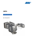
AMIRA
Q U I C K
G U I D E
Date: 02 April 2014
2
Imprint
Imprint
Copyright
© 2014 Arnold & Richter Cine Technik GmbH & Co. Betriebs KG. All rights reserved.
No portions of this document may be reproduced without prior written consent of
Arnold & Richter Cine Technik GmbH & Co. Betriebs KG. Specifications are subject to
change without notice. Errors, omissions, and modifications excepted.
AMIRA, ALEXA, and ALEXA XT are trademarks or registered trademarks of Arnold
& Richter Cine Technik GmbH & Co. Betriebs KG. All other brands or products are
trademarks or registered trademarks of their respective holders and should be treated
as such.
Original version.
NOTICE
This document is a Quick Guide only. For detailed operation instructions, please
refer to the User Manual.
For further assistance
Arnold & Richter Cine Technik GmbH & Co. Betriebs KG
Tuerkenstr. 89
D-80799 Munich, Germany
E-mail: [email protected]
www.arri.com/service
Document revision history
Version
ID
Release
Date
1.0
K4.0001898
K08511
02 April 2014
Contents
3
Contents
1
For your safety.................................................................................................5
1.1
Risk levels and alert symbols............................................................... 5
1.2
Vital precautions.................................................................................... 5
1.3
General precautions.............................................................................. 6
2
Audience and intended use............................................................................7
3
Scope of delivery and warranty..................................................................... 8
4
Camera layout.................................................................................................. 9
4.1
5
Product identification........................................................................... 13
Power supply..................................................................................................14
5.1
Changing a Gold Mount battery.......................................................... 14
5.2
Changing a V-Lock battery..................................................................15
5.3
BAT in..................................................................................................15
5.4
Powering auxiliary devices via camera............................................... 15
6
Switching on/off............................................................................................. 16
7
Connectors..................................................................................................... 17
8
9
10
7.1
Front connectors..................................................................................17
7.2
Audio connector panel.........................................................................18
7.3
I/O panel.............................................................................................. 20
7.4
Media panel......................................................................................... 22
7.4.1
Preparing a USB memory stick......................................................22
7.4.2
Changing a CFast 2.0 card............................................................23
Lens mount/filters..........................................................................................25
8.1
ND filter switch.................................................................................... 25
8.2
Changing a lens.................................................................................. 26
Audio control panel.......................................................................................27
9.1
Channel configuration..........................................................................27
9.2
Headphone volume............................................................................. 29
Main controls and viewfinder.......................................................................30
10.1
PK peaking button............................................................................... 30
10.2
EXP exposure tool button................................................................... 31
10.3
VF1 & VF2 user buttons..................................................................... 31
10.4
Recording.............................................................................................32
10.5
PLAY button........................................................................................ 33
10.6
Diopter adjustment.............................................................................. 33
10.7
Adjusting the monitor...........................................................................34
4
Contents
11
12
13
14
15
16
10.8
Changing the monitor mode................................................................34
10.9
Menu access....................................................................................... 35
User preset panel.......................................................................................... 37
11.1
Locking/unlocking................................................................................ 37
11.2
User buttons........................................................................................ 37
Operator panel............................................................................................... 39
12.1
Setting the US switch function............................................................ 39
12.2
Presetting the US / EI / WB switches..................................................40
12.3
AW auto white balance button............................................................ 41
Camera preparation....................................................................................... 42
13.1
Adjusting the viewfinder...................................................................... 42
13.2
Balancing the camera weight.............................................................. 43
13.3
Mounting to a wedge plate..................................................................44
13.4
Mounting to a bridge plate.................................................................. 45
Assembly and retrofits..................................................................................46
14.1
Battery adapter.................................................................................... 46
14.2
Base adapter....................................................................................... 48
14.3
Camera handle.................................................................................... 50
14.4
Viewfinder and EVF cable...................................................................51
14.5
Antennas..............................................................................................54
Licensing and updating................................................................................ 55
15.1
Camera updates.................................................................................. 55
15.2
Licensing..............................................................................................55
Appendix......................................................................................................... 56
16.1
Dimensions and weight (with PL mount).............................................56
16.2
Electrical data...................................................................................... 56
16.3
Declarations of conformity...................................................................56
For your safety
1
5
For your safety
Before use, please ensure that all users comprehensively read, understand, and
follow the instructions in this document.
1.1
Risk levels and alert symbols
Safety warnings, safety alert symbols, and signal words in these instructions indicate
different risk levels:
DANGER!
DANGER indicates an imminent, hazardous situation which, if not avoided, will
result in death or serious injury.
WARNING!
WARNING indicates a potentially hazardous situation which, if not avoided, may
result in death or serious injury.
CAUTION!
CAUTION indicates a potentially hazardous situation which, if not avoided, may
result in minor or moderate injury.
NOTICE
NOTICE explains practices not related to physical injury. No safety alert symbol
appears with this signal word.
Note: Provides additional information to clarify or simplify a procedure.
1.2
Vital precautions
DANGER!
High voltage! Risk of electric shock or fire!
Short-circuits will entail lethal damage.
Before use, read and follow all valid instructions.
Use solely and exclusively as described in the instructions.
Never open. Never insert objects.
For operation, always use a power source as indicated in the instructions.
Always unplug the power cable by gripping the power plug, not the cable.
Never try to repair. All repair work should be done by a qualified ARRI Service
Center.
Never remove or deactivate any safety equipment (incl. warning stickers or paintmarked screws).
Always protect from moisture, cold, heat, dirt, vibration, shock, or aggressive
substances.
Never cover any fan openings.
6
For your safety
CAUTION!
Condensation! Risk of electric shock and fire!
Condensation may form on the sensor and electrical connections when exposing
the camera to sudden changes of temperature or humidity.
To avoid injury and damage, never operate the camera when condensation occurs
CAUTION!
Heavy weight! Risk of injury and damage!
If placed on an unstable position, the camera can fall and cause serious harm.
Always place the camera on proper support devices. Safely attach it as described in
the instructions.
1.3
General precautions
NOTICE
Even rugged cameras use components sensitive to improper use.
Always unplug the camera from power sources before making changes to setup or
system (in particular: changing cables).
Protect the optical system and sensor: Never point the camera or viewfinder into
direct sunlight.
Avoid permanent sensor damage: Never let any direct light or reflections from highenergy light sources (e.g. laser beams) enter the camera's optical path.
Protect the sensor: Always keep a lens or protective cap on the empty lens mount.
Change lenses in dry, dust-free environments only.
Clean the sensor cover glass solely and exclusively as described in the User
Manual. If this fails, consult an ARRI Service Center. Never try to remove the glass.
Only use the tools, materials and procedures recommended in this document. For
the correct use of other equipment, see the manufacturer's instructions.
Audience and intended use
2
7
Audience and intended use
NOTICE
The product is solely and exclusively available for commercial costumers and shall
be used by skilled personnel only. Every user should be trained according to ARRI
guidelines.
Use the product only for the purpose described in this document. Always follow the
valid instructions and system requirements for all equipment involved.
The AMIRA is a 35 mm digital camera solely and exclusively for recording HD 1080 or
2K images suitable for a variety of distribution formats:
•
•
•
•
•
•
•
•
•
ProRes 422, ProRes 422 LT, ProRes 422 HQ* and ProRes 4444* codecs
REC 709 encoding (through use of look files) or Log C* encoding
CFast 2.0 card recording
Up to 200 fps* with full image quality
35 mm CMOS sensor
EVF with OLED eyepiece
Fold-away monitor for both live view and user interface access
Ready out-of-the-bag for single-user-centric workflow
Lean and rugged construction for high mobility
* Feature requires licensing.
8
Scope of delivery and warranty
3
Scope of delivery and warranty
NOTICE
Product and packaging contain recyclable materials. Always store, ship, and
dispose of according to local regulations.
ARRI is not liable for consequences from inadequate storage, shipment or disposal.
Delivery
On delivery, please check if package and content are intact. Never accept a damaged/
incomplete delivery. A complete delivery includes:
•
•
•
•
•
•
•
•
•
•
•
•
•
•
AMIRA camera with lens mount according to order: PL, EF, B4
Multi-viewfinder with AMIRA EVF cable
Gold Mount or V-Lock battery adapter, if ordered
Camera handle with viewfinder adapter
Four XLR connector caps (one spare; keep all four for later use!)
Four BNC connector caps (remove before use)
WPA-1 or BPA-3 base adapter, if ordered
WiFi antenna
Bluetooth antenna
USB memory stick
2 mm Allen key
3 mm Allen key
Quick Guide
Original packaging incl. drying agent
Usually, the camera comes fully assembled. In the unlikely case that a handle,
viewfinder, adapter, or antenna (etc.) is not assembled, see Page 46 for
instructions.
NOTICE
ARRI offers an increasing variety of product bundles and additional accessories.
For details, please consult our website or your local ARRI Service Partner.
Warranty
For scope of warranty, please ask your local ARRI Service Partner. ARRI is not liable
for consequences from inadequate shipment, improper use, or third-party products.
Camera layout
4
9
Camera layout
Right
2
3
4
1
5
6
9
1
2
3
4
5
8
BAT power input
I/O panel
Audio connector panel
Fan intake
12-pin Hirose for ENG type lenses
7
6
7
8
9
RS connector
Bracket rosette
WPA-1 with quick release connectors
Fan outlet
10
Camera layout
Left
1
10
1
2
3
4
5
Operator panel
User buttons
Power button & camera lock
Audio control panel
Lid
2
3
9
4
5
8
6
7
8
9
10
6
7
Media panel (behind lid)
Battery adapter
Fan intake
Recording button
Bracket rosette
Camera layout
11
Top
1
2
8
3
4
5
7
1
2
3
4
6
5
6
7
8
Viewfinder top buttons
Recording button
Viewfinder hinge with clamp
Accessory shoe
Adjustable beam
Camera type label
Level
Accessory threads on camera handle
Bottom
1
2
3
4
5
1
2
3
Battery adapter
Bracket rosettes
PLAY button
4
5
Viewfinder type label
WPA-1 quick-lock bracket
12
Camera layout
Front
1
2
3
5
4
1
2
3
4
5
Clamps
Lens mount (here: PL)
ND filter switch
15 mm rod receptacles
RS connector
Back
1
2
3
4
5
8
6
7
1
2
3
4
Fold-away monitor (viewfinder/GUI)
OLED eyepiece
Bluetooth antenna
WiFi antenna
5
6
7
8
I/O panel
BAT power input
Battery adapter (here: Gold Mount)
Proximity sensor for OLED eyepiece
Camera layout
4.1
13
Product identification
1
2
CE type labels with serial number are on the camera top (1) and under the viewfinder
(2). An FCC conformity label is on the camera bottom.
14
Power supply
5
Power supply
Depending on your battery demand, the camera offers either a Gold Mount or a VLock adapter. You can change both by yourself (see Page 46). For further details,
see our website or ask your local ARRI Service Partner.
NOTICE
For maximum operation time, always use fully charged batteries with 10.5 to 34 V
DC (50 W minimum).
5.1
Changing a Gold Mount battery
1
3
2
1. Place the battery pins in the mount receptors (1).
2. Slide the battery (2) to the right until the adapter audibly locks (1).
3. To release: With the lever pushed (3), slide the battery (2) to the left and
backwards.
Power supply
5.2
15
Changing a V-Lock battery
1
3
2
1. Place the battery's wedge into the V-shaped lock (1).
2. Slide the battery (2) downwards until the adapter audibly locks (1).
3. To release: With the pin pushed (3), slide the battery (2) up- and backwards.
5.3
BAT in
NOTICE
If the power supply to BAT is interrupted with the camera switched on, the camera
will automatically repower and boot-up on reconnection.
Use the BAT connector, and a KC50-S or KC50-SP-S cable, to
supply the camera with 10.5 to 34 V DC.
5.4
Powering auxiliary devices via camera
You can supply auxiliary devices from the camera via several connectors (2.0 A max):
• 12 V via 2-pin LEMO, 4-pin Hirose, or via D-tap on battery adapter
• 24 V via RS
• Camera voltage via EXT
Note: For connector pin-out information, see the User Manual. With a critical power
supply level, the camera switches off all auxiliary power supplies first.
16
Switching on/off
6
Switching on/off
1
2
3
1. To switch on: Press the power button (1).
2. The ARRI logo appears in audio display (2) and monitor (3).
3. To switch off: Press and hold the power button (1).
4. A countdown appears in audio display, monitor, and viewfinder.
5. On reaching zero, the camera powers off.
1
6. Note: The STBY icon (1) signals that the camera is ready to record.
7. If not: Insert a CFast 2.0 card. See Page 42.
8. Format the card for recording.
Connectors
7
17
Connectors
NOTICE
Connecting or disconnecting devices or cables while recording can disturb the
audio/image signal due to static electricity.
7.1
Front connectors
1
2
12-pin Hirose for ENG type
lenses
3-pin Fischer RS
1
2
ENG (12-pin Hirose)
Supplies lens servos with power and provides access to lens servo functions.
RS (3-pin Fischer)
This 3-pin Fischer socket for RS input supplies external accessories with 24 V power (2.0 A). It also carries a frame pulse output and accepts an ARRI remote start/stop trigger.
18
Connectors
7.2
Audio connector panel
NOTICE
Rubber caps protect the XLR connectors from dirt and moisture. Always cap
unused XLR connectors.
1
2
3
4-5
6
2
3
Protective caps
Headphone out & volume
XLR 5-pin audio input
XLR 3-pin audio input
Preset options
4
1
5
6
Headphone
Headphone 3.5mm stereo TRS (“Mini-jack”) output for monitoring
audio channels.
IN A (5-pin XLR)
XLR input for microphone signals (including 48V phantom power
supply) and line level signals.
IN B & C (3-pin XLR)
XLR input for microphone signals (including 48V phantom power
supply), line level signals and AES3 digital.
Connectors
19
Connecting audio devices
2
3
4
1
5
6
1. Uncap the needed connectors only (1).
2. Connect the headphone (2).
3. Set the headphone volume by turning the wheel (2).
4. Alternatively, you can use the SET wheel on the camera's left. See Page 29.
5. Via switch (3 to 5), select the appropriate setting for your audio device (6):
°
°
°
°
48V: Microphone level signals with phantom power supply
MIC: Analog microphone level signals
LINE: Analog line level signals
AES3: AES/EBU signals
6. Connect each device (3 to 5) until the connector audibly locks.
Disconnecting audio devices
1
1
1
1. Press the PUSH button to unlock (1).
2. Remove the cable by pulling on the connector.
3. Replace with another cable.
4. Or: Cap the connector for protection.
20
Connectors
7.3
I/O panel
NOTICE
If the power supply to BAT is interrupted with the camera switched on, the camera
will automatically repower and boot-up on reconnection.
3
4
5
2
6
1
7
1
2
3
4
5
6
7
BAT main power in
EXT in/out
D-tap
Aux power out
HD-SDI image out 1 & 2
Return/sync in
Timecode in/out
12V (4-pin Hirose)
Supplies 12 V auxiliary power with a maximum power of 2.0 A.
12V (2-pin LEMO)
Supplies 12 V auxiliary power with a maximum power of 2.0 A.
D-tap
A D-tap on the battery adapter supplies accessories with 12 V
DC from the camera.
Connectors
21
EXT (8-pin LEMO)
A connector for external accessories, carrying two CAN buses and accessory power output at camera voltage level (2.0 A
max.).
BAT (8-pin LEMO)
Via cables KC50-S (2 m, straight) and KC50-SP-S (coiled), this
main power supply input accepts 10.5 to 34 V DC.
SDI OUT 1 & 2 (BNC)
Both BNC sockets (here: SDI 1) deliver image outputs in
1920x1080 422 1.5G, 422 3G and 444 3G single link formats.
RET/SYNC IN (BNC)
A BNC socket for Genlock input, or HD-SDI return image signal**
(configurable). Supports Blackburst and Tri-Level Sync genlock
signals.
** Feature pending availability upon initial release version.
TC I/O (BNC)
A Timecode in-/output (BNC interface) to be configured via camera menu.
22
Connectors
7.4
Media panel
2
1
3
1
2
3
4
5
Lid
Status LEDs
CFast 2.0 card slots A & B
USB in/out 1 & 2
RJ45 Ethernet
4
5
Card A & B (CFast 2.0)
Storage media slots for CFast 2.0 recording cards.
USB 1 & 2
Interface for USB memory sticks with FAT file system. Can also
be used to charge USB devices.
Note: Only one USB memory stick can be used at a time. Independent from slot, the stick connected first becomes active.
Meanwhile, the second slot can still be used to charge a device.
Ethernet LAN
This RJ45 remote and service interface works via LAN.
7.4.1
Preparing a USB memory stick
USB memory sticks for the AMIRA must have a specific folder structure which can be
created with the camera.
Connectors
23
1
2
3
1. To prepare a USB memory stick: Open the media lid (1).
2. Connect a FAT-formatted USB stick (3) to the camera (2).
3. From the home screen, navigate to Menu > Media > Prepare USB medium.
4. Press CONFIRM to prepare the folder structure.
5. The USB stick (3) is now ready for use with the camera.
6. Note: To avoid file corruption, never remove the USB stick during write access.
7. You can remove the stick from the camera without unmounting.
7.4.2
Changing a CFast 2.0 card
NOTICE
Avoid damage to the contacts of both camera and card. Always insert cards as
described in this document.
Never change memory cards when recording - this may damage the recorded clip.
Other clips on the card will not be affected.
1
3
2
1. Open the lid (1).
2. Align the card's positive edge (3) facing the camera rear.
3. With the contact pins first, gently insert the card, until it audibly locks (2).
4. Gently close the lid (1). Never force it closed on an unlocked card.
5. To quickly change the active card you can set up a user button. See Page 38.
24
Connectors
1
2
6. For card removal: Open the lid (1).
7. Push the card in until it audibly unlocks (2).
8. Remove the card.
Lens mount/filters
8
25
Lens mount/filters
1
2
Lens mount (here: PL)
ND filter switch (clear - 0.6
- 1.2 - 2.1)
1
2
8.1
ND filter switch
The ND filter switch controls the internal ND filter module.
Filter densities of 0.6, 1.2 and 2.1 allow quick exposure
changes and compensation over a range of seven stops.
1. To activate a filter: Switch to the desired filter position.
26
Lens mount/filters
8.2
Changing a lens
NOTICE
The following description applies to PL mounts. For EF and B4 mounts, please refer
to the User Manual.
Protect the sensor: Always keep a lens or protective cap on the empty lens mount.
Change lenses in dry, dust-free environments only.
Never exceed the maximum lens dimensions.
Have every lens properly shimmed as prescribed by the manufacturer.
2
1
1. Observe maximum lens dimensions (see User Manual).
2. Counter-clockwise unlock (1) the lens mount and remove the lens or cap.
3. Never touch the sensor.
4. Either: Mount the next lens and clockwise lock (2) the lens mount.
5. Or: Always cap and clockwise lock (2) an empty lens mount.
Audio control panel
9
27
Audio control panel
1
2
3
4
2
Audio function switch
Audio display
Left/right gain controls
Audio SET jogwheel
3
1
9.1
4
Channel configuration
NOTICE
Audio is disabled if the sensor frame and project rates are not equal. With audio
recording disabled or otherwise switched off, neither audio in/output nor audio
processing is possible.
Checking the audio status
2
3
1
4
1. Select INFO (1) to display current status information (2).
2. L and R (3) are now deactivated.
3. Select 1/2 or 3/4 (1) to configure the respective audio channels (2).
28
Audio control panel
Adjusting channel gain
2
3
1
4
1. Select 1/2 or 3/4 (1).
2. Adjust channel 1 (or 3) gain via L wheel (3).
3. Adjust channel 2 (or 4) gain via R wheel (3).
4. To change channel 1/2 (or 3/4) setup: Select and edit the desired parameter via
SET jogwheel (4).
5. To enter the edit mode: Press SET (4).
6. To change a parameter: Press and turn the SET jogwheel (4).
7. To confirm and leave the edit mode: Press SET (4) again.
Editing the audio setup
2
3
1
4
1. Select SETUP (1) for adjusting overall audio parameters (2).
2. To navigate and adjust: Press and turn the SET jogwheel (4).
3. To enter or confirm: Press SET (4).
Audio control panel
9.2
29
Headphone volume
2
3
1
4
1. Switch to INFO (1).
2. For headphone volume control: Press and turn the SET jogwheel (4).
3. Alternatively, use the headphone volume wheel. See Page 19.
4. The volume level appears in the display (2), next to the headphone icon.
30
Main controls and viewfinder
10
Main controls and viewfinder
2
3
9
4
1
2
3
4
5
6
7
8
9
10
5
1
8
9
Monitor (Live & GUI)
Peaking button
Exposure tool button
VF1 & VF2 user buttons
Monitor button
Proximity sensor
Diopter control
Recording button
Screen buttons
Jogwheel
7
6
10
Proximity sensor
This infrared sensor automatically deactivates the viewfinder's internal OLED panel when you withdraw your eye.
Note: To avoid hardware damage, always keep the sensor clear.
10.1 PK peaking button
2
1
3
1. To activate peaking on monitor (1) and viewfinder (3): Press PK (2).
2. Peaking highlights the image parts that are in focus for better focus judgement.
3. For PK setting: Go to MENU > EVF/Monitor/SDI > EVF/Monitor > Peaking.
Main controls and viewfinder
31
10.2 EXP exposure tool button
2
1
3
The EXP button (2) activates the set exposure tool on the monitor (1) and EVF image
(3). Use the tool for evaluation of the image exposure levels. An activated tool lights
up the button.
For EXP setting: Go to MENU > EVF/Monitor/SDI > EVF/Monitor > Exposure tool. Two
modes are available:
Zebra overlays up to two luminance ranges with diagonal stripes. High zebra ranges
above, Mid zebra around, the user-defined luminance value.
False color overlays predefined luminance ranges as follows:
Luminance range
Signal level
Color
White clipping
100 to 99 %
Red
Just below white clipping
99 to 97 %
Yellow
One stop over medium gray (Caucasian skin)
56 to 52 %
Pink
18 % medium gray
42 to 38 %
Green
Just above black clipping
4.0 to 2.5 %
Blue
Black clipping
2.5 to 0.0 %
Purple
10.3 VF1 & VF2 user buttons
1
1. Via the camera menu (see Page 36 and Page 38), you can assign a
function to both VF1 and VF2 buttons (1).
32
Main controls and viewfinder
10.4 Recording
NOTICE
Pressing a recording button returns the user interface to the home screen and
disables the menu access.
Recording also disables the US switch and the home screen buttons for FPS, TC,
Shutter, and Look settings.
1
1. Prepare the camera.
2. Preset all switches and buttons.
3. Press REC (1) on the left camera side.
1
4. Alternatively, press REC (1) on the viewfinder.
NOTICE
Never change memory cards when recording: It may damage the recorded clip.
Other clips on the card will not be affected.
NOTICE
Connecting or disconnecting devices or cables while recording can disturb the
audio/image signal due to static electricity.
Main controls and viewfinder
33
10.5 PLAY button
1
1. Press PLAY (1) to see the last clip of the active CFast 2.0 card.
2. Playback is active on monitor, on EVF and on SDI out.
3. To leave playback: Press PLAY (1) for one second.
4. Or: Press the EXIT screen button.
5. To select other clips, use the on-screen navigation. For details, see the User
Manual.
10.6 Diopter adjustment
1
1. Twist the ring left or right for diopter adjustment (1).
34
Main controls and viewfinder
10.7 Adjusting the monitor
1
3
2
1. Fold (1), swivel (2) and flip (3) the monitor according to your needs.
10.8 Changing the monitor mode
1
1. To change the monitor mode between live view and user interface: Press M (1).
Main controls and viewfinder
35
1
1
2. In live mode, toggle the status bar content (1) via the lower buttons.
1
2
3
3
3. Via camera menu, you can activate a location sensor that automatically flips the
user interface to match a left- or right-sided monitor position (3).
4. Note: the jogwheel (1) and the screen buttons (2).
10.9 Menu access
The user interface centers around the home screen, with access to essential status
parameters and camera functionalities:
1
2
3
1
2
3
4
4
5
9
8
7
6
5
6
7
8
9
!: Alert messages
FPS: Sensor frame rate
TC: Timecode
SHUTTER: Shutter angle or, if chosen
instead, exposure time
STBY: Camera standby status
WB: White balance
LOOK: Gamma settings and look files
EI: Exposure index
İ: Info messages
36
Main controls and viewfinder
2
1
3
5
1. To enter the MENU: Press the jogwheel (1).
2. Scroll with the jogwheel (2) up or down to the desired entry (4).
3. To enter: Press the jogwheel (2).
4. Entries with an arrow navigate to a lower menu level.
° To navigate deeper: Use the jogwheel (2).
° To return to a higher menu: Press BACK (5).
5. Entries with a value allow direct editing.
° To edit a value: Turn the jogwheel (2).
° To confirm and end editing: Press the jogwheel (2).
° To cancel editing: Press BACK (5).
6. To leave the menu: Press HOME (3).
4
User preset panel
11
37
User preset panel
1
2
3
4
1
2
Power button
Camera lock
User buttons
SHIFT button
3
4
11.1 Locking/unlocking
NOTICE
Locking the camera disables, unlocking re-enables, all camera controls except
recording and audio.
On a locked camera, never switch US, EI, WB, or ND into a new position.
Otherwise, unlocking will change the switch presetting.
1
2
1. Press and hold LOCK (2).
2. A countdown appears in both monitor and viewfinder. Once the countdown
reaches zero, the camera is locked.
3. To unlock: Press and hold LOCK (2) again.
11.2 User buttons
In the camera menu (MENU > User buttons) you can assign individual functions to
each user button. For full instructions, see the User Manual.
38
User preset panel
1
2
1. Press a button (1) to trigger its function.
2. For buttons five to eight: Press and hold SHIFT (2); then press a button (1).
3. An LED on each button reflects the functional status.
4. To check the functional status of buttons five to eight (1): Press SHIFT (2).
Presetting user (and VF) buttons
1
2
3
5
1. Toggle from live monitor to home screen. See Page 34.
2. Press wheel (1) for MENU.
3. Wheel-navigate (2) to User buttons > Button x (4) and enter (2).
4. Wheel-navigate to the desired function and enter (2).
5. If applicable: Wheel up or down (2) to the desired value.
6. To cancel: Press BACK (5).
7. To confirm: Press the wheel (2).
8. To conclude: Press HOME (3).
9. If applicable: Repeat for all other buttons, including VF1 and VF2.
4
Operator panel
12
39
Operator panel
NOTICE
The operator panel consists of switches that offer quick changes of important
camera functions, such as exposure index or white balance.
For all switch positions (except ND positions), you can assign an individual
presetting. See the User Manual for full instructions.
1
2
3
1
2
3
4
5
12.1 Setting the US switch function
1
1. Switch US (1) to the desired position.
4
5
User switch & settings
Exposure switch & settings
White balance switch &
settings
Auto-white balance button
Recording button & LED
40
Operator panel
2
1
3
4
5
2. From the home screen, navigate (1) to MENU > User > User buttons (4).
3. Via jogwheel (2), select the entry User switch and change it according to your
needs:
None: User switch is disabled
FPS: Switch changes the sensor frame rate
SHUTTER: Switch changes the shutter angle
EXP Time: Switch changes the exposure time
Look: Switch changes the look file
°
°
°
°
°
4. Leave the menu by pressing HOME (3).
5. Note: Recording disables the US switch.
12.2 Presetting the US / EI / WB switches
1
2
3
5
4
1. On the home screen, select a switch function (here: FPS) by pressing the button
(1).
2. Note: Active functions show a switch icon in the button label.
3. You can change only the preset of the active switch position.
4. Change the switch to the desired position.
5. Press the SET XX button (4).
6. Via jogwheel (2), select the desired preset.
7. Confirm by pressing the wheel (2).
8. Repeat for other switch positions if desired.
Operator panel
41
9. For FPS, SHUTTER, LOOK, and WB, you can configure preset lists for each
switch position.
10. See the User Manual for detailed instructions.
12.3 AW auto white balance button
The AW button triggers the auto white balance functionality: Based on the camera's
live image, AW calculates an automatic white balance and overwrites the active WB
settings. The AW result is stored as the preset value of the active WB position.
AW triggering
1
1. To trigger an automatic white balance: Press AW twice within one second (1).
42
Camera preparation
13
Camera preparation
13.1 Adjusting the viewfinder
1
2
3
1. Slightly loosen the clamp (1) to move the viewfinder (2) left/right and up/down.
2. Unclamp the hinge (3) to swivel the viewfinder horizontally.
3. Close all clamps (1, 3) when the viewfinder is in the desired position (2).
Camera preparation
43
13.2 Balancing the camera weight
1
4
2
3
1. Unlock (4) and slide the base adapter (3) until the camera is balanced.
2. Close the clamp (4).
3. Unclock (1) and slide the handle (2) until the camera is balanced.
4. Close the clamp (1).
44
Camera preparation
13.3 Mounting to a wedge plate
1
2
1. For mounting to a wedge plate, use the WPA-1 wedge plate adapter.
2. Open the quick-release base plate.
3. Place the adapter (1) into the quick-lock plate slighty behind the connection points.
4. Slide the camera forward until the quick-lock audibly locks (2).
5. Note: The lock must be closed.
Camera preparation
45
13.4 Mounting to a bridge plate
NOTICE
Always use a flat screwdriver to connect the BPA-3 to a bridge plate. Never use a
coin. A coin does not deliver enough force to ensure proper lock.
1
3
2
1. For mounting to a bridge plate, use the BPA-3 bridge plate adapter.
2. Place the bridge plate unter the adapter (1).
3. Adjust the bridge plate's nose (3) to the adapter's aperture.
4. With a flat screwdriver (no coin!), attach the screws to the adapter and tighten (2).
5. Note: Always ensure proper lock.
46
Assembly and retrofits
14
Assembly and retrofits
NOTICE
To avoid damage while assembling and retrofitting, always place the camera on a
padded, firm, flat and level surface.
Work on an unpowered camera only.
14.1 Battery adapter
Tools needed
• 2.5 mm Allen key
Mounting
1
2
1. Note: The illustration shows a V-Lock adapter.
2. Switch off; interrupt the power supply.
3. Pin the battery adapter (1) to the camera.
4. With a 2.5 mm Allen key, fasten all three screws (2) until the adapter fits tightly.
Assembly and retrofits
47
Unmounting
1
2
1. Note: The illustration shows a Gold Mount adapter.
2. Switch off; interrupt the power supply.
3. With a 2.5 mm Allen key, unfasten all three screws (2).
4. Remove the battery adapter (1).
48
Assembly and retrofits
14.2 Base adapter
Mounting
1
1
3
2
1. Note: The illustration shows a WPA-1.
2. Open the clamp (1).
3. Slide the adapter under the camera (3).
4. Note: The safety pin (2) must audibly lock.
5. Close the clamp (1).
Assembly and retrofits
49
Unmounting
1
1
3
1. Note: The illustration shows a BPA-3.
2. Open the clamp (1).
3. With the safety pin pulled (2), slide the adapter off the camera (3).
2
50
Assembly and retrofits
14.3 Camera handle
1
2
3
1. Open the clamp (1).
2. Slide the handle onto the camera (2).
3. Note: The safety pin (3) must audibly lock.
4. Close the clamp (1).
5. To unmount: Open the clamp (1).
6. With the safety pin pulled (3), slide the handle off the camera (2).
Assembly and retrofits
51
14.4 Viewfinder and EVF cable
Tools needed
• 2 mm Allen key
EVF port
Via original AMIRA EVF cable, this port connects the camera to
the multi-viewfinder.
Changing the EVF cable
1
2
1. Note: Use original AMIRA EVF cables only.
2. Place the camera bottom-down.
3. Unmount the camera handle. See Page 50.
4. With a 2 mm Allen key, unscrew and remove the lid (1).
5. Either: Connect the cable (2) to the EVF port.
6. Or: Disconnect the cable (2).
7. Reattach lid (1) and camera handle.
52
Assembly and retrofits
Changing the viewfinder
1
2
1. Switch off; interrupt the power supply.
2. Note: Use original AMIRA EVF cables only.
3. Connect a EVF cable to the camera. See Page 51.
4. With your fingers, unscrew and remove the viewfinder’s lid (1).
5. Either: Connect the cable (2) to the EVF port.
6. Or: Disconnect the cable (2).
7. Reattach the lid (1).
Assembly and retrofits
53
1
2
8. Open the clamp (1).
9. Either: Dovetail the viewfinder to the bracket (2).
10. Or: Unbracket (2) and remove the viewfinder.
11. Close the clamp (1).
54
Assembly and retrofits
14.5 Antennas
2
1
1. With your fingers, thread the antennas for WiFi (1) and Bluetooth (2) onto the
camera.
2. To unmount: Unthread the antennas (1, 2) with your fingers.
WiFi
Antenna for WiFi signal according 802.11g. Used for remote
camera access.**
** Feature pending availability upon initial release version.
Bluetooth
Antenna for bluetooth signal. Used for wireless audio monitoring
and comment channel return with bluetooth headset. Supports
Handsfree and A2DP protocols.**
** Feature pending availability upon intial release version.
Licensing and updating
15
55
Licensing and updating
Tools needed
•
•
•
•
Sufficient power supply
Product key
Internet access
FAT-formatted USB memory stick with a camera-compatible folder structure.
See Page 22
15.1 Camera updates
The camera supports the installation of SUP software update packages. Check
www.arri.com for the latest available SUP version.
To install an update, follow the instructions coming with the SUP.
15.2 Licensing
You can further enhance the camera capabilities through licensed features available
for online purchase. Visit the ARRI license shop at http://alshop.arri.de and follow the
instructions for purchasing and downloading license keys.
License keys are linked to each camera's serial number and cannot be transferred
from one camera to another.
1
2
3
5
The list of installed licenses on your camera is available under: Menu > System >
Licensed feature (4).
For full instructions, see the User Manual.
4
56
Appendix
16
Appendix
16.1 Dimensions and weight (with PL mount)
Length
309 mm
Height
149 mm
Width
139 mm
Weight
4.1 kg
16.2 Electrical data
DC power input
10.5 to 34 V
DC power output
10.5 to 12 V (RS: 24 V) / 2.0 A
Operation temperature
-20 to +50 °C (-4 to +122 °F)
16.3 Declarations of conformity
EC Declaration of Conformity
The product AMIRA 1 conforms with the specifications of following European
directives:
• Directive 2004/108/EC Community directive for the adaptation of legal
regulations of member countries regarding electromagnetic compatibility
• Directive 199/05/EC Radio equipment and telecommunications terminal
equipment and the mutual recognition of their conformity
• Directive 2011/65/EC on the restriction of the use of certain hazardous
substances in electrical and electronic equipment
The compliance with the requirements of the European Directive was proved by the
application of the following harmonized standards:
•
•
•
•
•
•
EN 55103-1:2009 / EN 55022:2010
EN 55103-2: 2009
EN 301 489-1:2011
EN 301 489-17:2012
EN 62479:2010
DIN EN 50581:2013-02
Appendix
57
FCC Compliance Statement
Class A Statement: This equipment has been tested and found to comply with the
limits for a Class A digital device, pursuant to Part 15 of the FCC Rules. These limits
are designed to provide reasonable protection against harmful interference when the
equipment is operated in a commercial environment.
Note: This equipment generates, uses, and can radiate radio frequency energy and, if
not installed and used in accordance with the instruction manual, may cause harmful
interference to radio communications. Operation of this equipment in a residential area
is likely to cause harmful interference in which case the user will be required to correct
the interference at his own expense.
• WLAN: FCC ID: PD962205ANH
• Bluetooth: FCC ID: QOQWT32AE
Industry Canada Compliance Statement
Complies with the Canadian ICES-003 Class A specifications.
Cet appareil numérique de la Classe A est conforme à la norme NMB-003 du Canada.
This device complies with RSS-210 of Industry Canada.
Cet appareil est conforme à CNR-210 d' Industrie Canada.
This Class A device meets all the requirements of the Canadian interference-causing
equipment regulations
Cet appareil numérique de la Classe A respecte toutes les exigences du Réglement
sur le matériel brouilleur du Canada.
• WLAN: IC ID: 1000M-62205ANH
• Bluetooth: IC ID: 5123A-BGTWT32AE