1
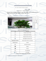
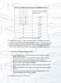
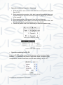
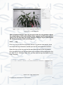
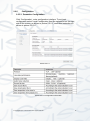
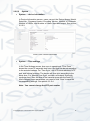
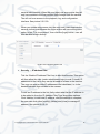
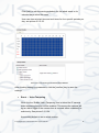
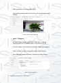
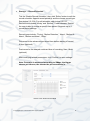
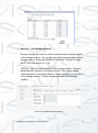
USER MANUAL 2MP IR MINI PTZ CAMERA IPTZ-P400-10X © Copyright Qvis ®. All documentation rights reserved. V 1.0 08.2015 © Copyright Qvis ®. All documentation rights reserved. Welcome Thank you for purchasing the 2MP IR Mini PTZ Camera. This user’s manual is designed to be a reference tool for the installation and operation of your system. Here you can find information about the corresponding IP camera’s features and functions, as well as a detailed installation method. Before installation and operation please read the following safeguards and warnings carefully! © Copyright Qvis ®. All documentation rights reserved. Precautions 1.Electrical safety All installation and operation here should conform to your local electrical safety codes. The power supply shall conform to the requirement in the SELV (Safety Extra Low Voltage) and must make sure that the limited power source is rated 12V DC or 24V AC. Please note: Do not connect two power supplying sources to the device at the same time; it may result in device damage! We assume no liability or responsibility for all the fires or electrical shock caused by improper handling or installation. We are not liable for any problems caused by unauthorized modification or attempted repair. 2.Transportation Security Please ensure that the product does not endure heavy stresses, violent vibration or contact with water during transportation, storage and installation. Please use the original packing material (or the material of the same quality) if you need to return it to vendor. 3.Installation Do not apply power to the product before completing installation. Do not put object(s) on the product. Please install a proper power cut-off device during the installation connection. 4.Qualified engineers needed All the examination and repair work should be done by the qualified service engineers. We are not liable for any problems caused by unauthorised modifications or attempted repair. 5. Environment This product should be installed in a cool, dry place away from direct sunlight, inflammable, explosive substances and etc. Please keep it away from environments that contain electromagnetic radiation or objects that produce it. Please keep sound ventilation around the device at all times. © Copyright Qvis ®. All documentation rights reserved. Do not allow the water and other liquid to penetrate into the device if casing has been compromised. This series product complies with the IP66 standard specified in the Degrees of Protection Provided by Enclosure. Ensure lightning surge protection is in place to make sure you fully protect camera circuitry from electrical overload. Please make sure the CCD (CMOS) component is away from the radiation of the laser beam device. Otherwise it may result in CCD (CMOS) optical component damage. It is recommended that the grounding studs of the product should be grounded, so to further enhance the reliability of the camera. Avoid shooting very bright objects directly into the camera’s CCD (such as the sun or light fittings), and avoid fixating the camera lens on bright static object for long time, as it will cause Irreparable damage to the camera’s CCD. 6. Daily Maintenance Please shut down the device and then unplug the power cable before you begin any maintenance work. Do not touch the CCD (CMOS) optic component. Please use an air jet to clean the dust off the lens surface. You can use the dry cloth with some alcohol or mild detergent to clear if necessary. When the camera is not in use please put the dustproof cap to protect the CCD (CMOS) component. Do not use volatile solvent such as the benzene, paint thinner or detergent with the ability to abrade surfaces. It may result in lens damage or adversely affect the device’s performance. 7. Accessories Always use all the accessories recommended by manufacturer. Before installation, please open the package and check that all the components are included. Contact your local retailer/vendor ASAP if something is missing. © Copyright Qvis ®. All documentation rights reserved. Table of Contents 1 2 General and Technical Features......................................................................................... 1 1.1 Special Features ……………………………………………….. ....................................... 1 1.2 Function Introduction ..................................................................................................... 2 1.3 PTZ Camera Integration ................................................................................................ 2 1.4 All-Weather Outdoor Design ......................................................................................... 2 1.5 Preset Position Set Up and Call Up .............................................................................. 3 1.6 Auto Scan ...................................................................................................................... 3 1.7 Cruising Track ............................................................................................................... 3 1.8 Pattern Tour................................................................................................................... 3 1.9 Technical Parameters ................................................................................................... 4 1.10 OSD Menu Operation .................................................................................................. 4 Web Browser Operation Guide ........................................................................................... 5 2.1 Common Operations ..................................................................................................... 5 2.1.1 Factory settings .......................................................................................................... 5 2.1.2 Network parameters ................................................................................................... 5 2.2 Web Login ..................................................................................................................... 7 2.2.1 Login ........................................................................................................................... 7 2.2.2 Download playing component .................................................................................... 7 2.2.3 Playback ................................................................................................................... 11 2.2.4 Log............................................................................................................................ 12 2.2.5 Configuration ............................................................................................................ 13 2.2.5.1 Parameter Configuration ....................................................................................... 13 2.2.5.2 System................................................................................................................... 14 2.2.5.3 Network ................................................................................................................. 16 2.2.5.4 Audio/Video ........................................................................................................... 22 2.2.5.5 Image..................................................................................................................... 24 2.2.5.6 Safety .................................................................................................................... 28 © Copyright Qvis ®. All documentation rights reserved. 3 OSD Menu Function ................................................................................................................ 37 3.1 Information....................................................................................................................... 37 3.2 Language......................................................................................................................... 38 3.3 IR Leds ............................................................................................................................ 39 3.4 Idle ................................................................................................................................... 40 3.5 Mask ................................................................................................................................ 41 3.6 Alarm ............................................................................................................................... 42 3.7 PTZ Display ..................................................................................................................... 43 3.8 Image............................................................................................................................... 44 3.9 Exposure ......................................................................................................................... 45 3.10 Focus ............................................................................................................................. 46 3.11 WDR .............................................................................................................................. 47 3.12 White Balance ............................................................................................................... 48 3.13 Image Enhancement ..................................................................................................... 49 3.14 Image Adjustment ......................................................................................................... 50 3.15 Default ........................................................................................................................... 51 3.16 Scan .............................................................................................................................. 52 3.17 Sequence ...................................................................................................................... 53 3.18 Pattern ........................................................................................................................... 54 3.19 Restart ........................................................................................................................... 55 3.20 Default ........................................................................................................................... 56 © Copyright Qvis ®. All documentation rights reserved. 1. General and Technical Features 1.1 Special Features High Definition Footage Shoot video footage using MPEG H.264 compression at varying frame rates, which allows you to save network bandwidth without compromising on footage quality. You will also be able to adjust the aspect ratio of the video footage to either 16:9 or 4:3. Also supports dynamic coding within footage settings. Fixed Focus/Veri-focus/Automatic focusing In built 10 x optical zoom, veri-focus (variable focus) and automatic focusing function. The automatic focusing function will adjust image to optimum clarity whilst changing the zoom amount and what direction the camera is pointing towards. Double Stream Option Supports double streaming (Main & Sub streams). Multiple Supported protocols Supports: TCP/IP, PPPoE, DDNS, FTP, UPNP, Onvif, etc. Voice intercom function 1 x Audio In, 1 x Audio Out. Two Way audio ability. Alarm function Supports local and wide area network signal linkage; Link to a networked alarm system using the network input/outputs. Region of Interest Stream concentration makes the drawing region clearer. OSD function Setup the camera with its onboard setup user interface, via a connected monitor. © Copyright Qvis ®. All documentation rights reserved. 1 1.2 Function Introduction Infinitely variable speed, softened zoom and automatic speed matching technology Lowest manual operational movement speed:0.01º/S, Fastest manual operational movement speed with precise positioning: 12º/S 256 tour presets. Supports auto sequence function, and 8 sequence paths (each path could store 32 preset positions). 8 auto scans; set left and right boundary and scan speeds. 4 pattern path; each path can record more than 500 different orders or 600 seconds of path movements. Built-in 1 x Alarm In, 1 x Alarm Output (optional). Alarm linkage function; connect camera to an alarm system so that when an alarm is triggered, the alarm calls up programmed preset, which includes: position/sequence/pattern/TF card scan video captured picture/trigger switch output/intelligent snapshot/FTP uploading/mail linkage; 1.3 PTZ Camera Integration New gear reversing technology, which improves the level of integration and transmission accuracy New type of ultra-thin precision stepper motor drive; stable running and accurate positioning 1.4 All-Weather Outdoor Design IP66 Protection standard TVS 3000V Protection standard © Copyright Qvis ®. All documentation rights reserved. 2 1.5 Preset Position Set Up and Call Up Within the Preset function the camera stores the current pan/tilt angle, zoom, and other position parameters into memory. When necessary the camera recalls these parameters and adjusts the camera to a particular position. The user can store, recall and clear the presets easily and promptly by using the keyboard controller. The camera can store up to 256 presets. 1.6 Auto Scan Users can set up the left and right boundaries by using a control keyboard. Then the camera can scan between these boundaries. It can support up to 8 scanning path groups. 1.7 Cruising Track The preset position can be programmed to be recalled in a set of sequences. This sequence can be set to let the camera scan from one position to the next in a cycle at a set speed. This feature is called the ‘auto cruise’. The cruise sequence and dwell time of each preset can be set. It supports up to 8 cruising tracks, each cruising track with 32 presets. 1.8 Pattern Tour Camera can memorize 600 second running paths or 500 programmable instructions. When starting a pattern tour, the camera will move automatically according recorded action path. It supports 4 groups of pattern tours. © Copyright Qvis ®. All documentation rights reserved. 3 1.9 Technical Parameters 1.10 OSD Menu Operation Call up OSD menu Call Preset 95 to enter the main OSD menu; call Preset 96 to close the OSD menu or Select ‘Exit’ Confirm The ‘Left ‘and ‘Right ‘button is controlled by PTZ can change the required item, and the changed item is the confirmed one without further confirmation. You can directly click ‘Up’ and ‘Down’ button to go on your further operation. When setting the left and right boundary for scan and pattern, you can click the ‘Focus Far’ for confirmation. Cancel The ‘up’ and ‘down’ button controlled by PTZ carry out the request for Further action; meanwhile, it carries out the ‘Cancel’ order for last operation. © Copyright Qvis ®. All documentation rights reserved. 4 2. 2.1 2.1.1 Web Browser Operation Guide Common Operations Factory settings An IP camera is classified as a type of network equipment, you need to configure its network IP address, gateway, and other information to fit within the network it is being integrated into. The camera comes with a default factory IP address, which the user can change it according to their setup requirements. Default factory IP settings: Default IP address:192.168.0.99 Subnet mask:255.255.255.0 Gateway:192.168.0.1 WEB port:8000 2.1.2 Network parameters You will need to connect the camera to a PC with Windows installed, in order to check the camera’s IP network parameters and to see if there is a successful connection. Make sure the default factory IP details of the camera is within the network parameters of the user computer, and also within the same network address segment. The IP address of the camera and the LAN cannot be the same, otherwise they will interfere with each other, causing the equipment to not operate correctly together. Connect the camera to the PC by firstly connecting an Ethernet cable between the camera and the PC’s NET port, and then provide power to the camera using the power adapter. To test whether it has been successfully connected, use the PING order within the ‘cmd’ console. © Copyright Qvis ®. All documentation rights reserved. 5 To find the ‘cmd’ console in Windows, firstly search for ‘cmd’ on your computer, the icon for it should look like this: Once loaded, the format of the command needs to be: ping 192.168.0.99 If the camera is correctly setup and connected the cmd console should display this: As the picture shown above, it indicates that there has been a successful connection between the computer and the camera. However, if the screen display like this: This indicates a connection failure. To solve the connection issue please check the following: If the hardware is correctly connected together If computer TCP/IP is within the same segment as the camera If network forbids the ping order, please contact the network administrator to gain permission. © Copyright Qvis ®. All documentation rights reserved. 6 2.2 Web Login 2.2.1 Login Open up web browser within the Windows interface, enter default factory IP address (192.168.0.99) to open the camera’s web interface. A dialog box will be shown as follows: Picture 2.2.1-1 login interface User name:Admin Password:Admin Port:Default 8000 2.2.2 Download playing component After you have logged in, if the WEB browser indicates this is the first time you’ve logged in and will ask for you to install the latest plug-in version. (See Picture 2.2.2-1). Click ‘OK’ and the plugin will be downloaded. You can also double-click the icon at the top-right corner of the login interface to download plugin (see Picture 2.2.1.1, highlighted by the red box). Double-click the downloaded WebPluginInstaller.exe and start & complete the installation for web browser. You need to return to the web browser screen and refresh the display (press F5 key) if you want to run this plug-in after installation, then you will be able to watch the ‘preview’ video stream from the camera. © Copyright Qvis ®. All documentation rights reserved. 7 Picture 2.2.2-1 Plug-in installation After you have installed the plug-in; input user name, code, and then click the ‘login ‘button to enter the ‘preview ‘screen. See 2.2.2-2 Picture 2.2.2-2 Preview screen Sheet 2.2.2-3 Preview screen information © Copyright Qvis ®. All documentation rights reserved. 8 Sheet 2.2.2-4 PTZ control screen information In the preview screen, you can control the camera’s streamed video, which includes control over video recording, snapshot, intercom, and the on/off of the sound. The size of the image can be adjusted according to the needs of the user to set its original size; we have ‘4:3’, ‘16:9’ or ‘Self-adaptation’ mode. Preview code stream can be set as ‘main stream’ ‘sub stream’. See 2.2.2-3 Operation methods for preset position 1. Find the preset section to the interface, and it will show the current preset camera position. 2. Setting a preset position; select a preset position number, and then operate direction of the camera using the directional controls. 3. When the camera scene moves to the place you want to set, then click the ‘save ‘key’ to save this preset position. 4. Call the preset position: click ‘call ‘and the set preset position can be called. 5. Delete preset position: click ‘delete’ can clear the information of preset position. 6. Special function preset position; this kind of preset position can be called, but it cannot be modified or deleted. © Copyright Qvis ®. All documentation rights reserved. 9 Operation methods for pattern scanning 1. Enter the pattern scan screen, it will show the current pattern scan path. See 2.2.2-5 2. Start recording the scanning; click start to record the pattern scan, and the start using the camera directional controls to adjust the movement of the camera. 3. Stop recording scan; click save to save the scanning path. 4. Start and stop the pattern scan: click start to start the pattern scan, and click the stop key to stop the pattern scan. See 2.2.2-6. 5. Delete the pattern scan: click delete key to delete the pattern scan. Picture 2.2.2.5 Sequence settings Picture 2.2.2-6 Pattern settings Operation methods for IR LED Enter the IR LED setting screen to set the power of the low beam lights between 1~10 amounts, the power of high beam lights, low beam lights compensation, enable illumination, and IR status setting. See 2.2.2-7 Picture 2.2.2-7 IR LED Setting Screen © Copyright Qvis ®. All documentation rights reserved. 10 Auto scanning setting Enter the auto scan screen to set scan speed, left boundary, right boundary, start scan, and to stop scan. Auto scanning include 8 scanning paths. See 2.2.2-7 Picture 2.2.2-8 Auto scans settings 1. Scanning speed: from 1~100, the larger the gap between numbers, the more evident the effect will be. 2. To set left boundary and right boundary of the scan: first make the camera move to a specified direction and then click the left boundary icon. Move the camera to a right hand direction, stop camera movement and then click the right boundary. Finally click the start key and the camera will move in the range of the left and right limit. Click stop to stop the movement. 3. It will be the same setting methods explained in the previous point above to set other auto scanning paths. 2.2.3 Playback Click ‘Playback’ to enter the video search playback screen. The Playback screen can inquire, playback and download effective video that has been saved on to the SD card of the camera. Select the inquiry type, start & end time, then click the ‘Search’ key, and the eligible video files will be displayed in the right box. Select it and double-click to open, and then the video files will start to playback. See 2.2.3-1. © Copyright Qvis ®. All documentation rights reserved. 11 Picture 2.2.3-1 video playback Note: playback function can only be used under the circumstance when the camera has an SD card installed. If the camera has SD card, and it is using it for the first time you must click the ‘Storage’ key to initialise the SD card and set the video-recording plan. 2.2.4 Log Click ‘Log’ key to enter the log inquiry screen. Log screen can search, show and output the log information stored upon the SD card within the camera. Select the type of the log, and set the start and end time of the log-search. Click the search key, and all the eligible log information will be displayed in the list. See 2.2.4-1. Click the ‘Save’ key, you can save the log information to your local computer. Picture 2.2.4-1 log record screen © Copyright Qvis ®. All documentation rights reserved. 12 2.2.5 Configuration 2.2.5.1 Parameter Configuration Click ‘Configuration’, enter configuration interface. To set local configuration select ‘Local Configuration from the options list on the right side of the screen, as shown in picture 2.2.5-1, each item instruction as shown in picture 2.2.5-2 Picture 2.2.5-1 Picture 2.2.5-2 configuration information © Copyright Qvis ®. All documentation rights reserved. 13 2.2.5.2 System System → device information In Device Information screen, users can set the Device Name, Model, Serial No., Firmware Version, Encoding Version, Number of Channels, Number of HDDs, and Number of Alarm input and output. See picture 2.2.5-3 Picture 2.2.5-3 device information System → Time settings In the Time Settings screen, time sync is operational. ‘Time Zone’ shows the current IP camera’s time zone, and that can be set according to the actual situations. For ‘Time Sync’, set NTP server address, NTP port, and Interval minutes. The device will time sync according to the setup time. For ‘Manual Time Sync’, set time, and check ‘Sync with computer time’, then the time of the camera syncs with the local PC. After changing some parameters you need to click ‘Save’ to save the corresponding settings. See picture 2.2.5-4 Note:You cannot change the NTP port number © Copyright Qvis ®. All documentation rights reserved. 14 Picture 2.2.5-4 Time settings System→ Maintenance Enter system maintenance interface, See picture 2.2.6-5. Click ‘Reboot’ to reboot the device. Click ‘Restore’ to restore device parameters. It will easily restore the other parameters except IP address, subnet mask, gateway, 8000 port number, DNSS address and user name management information. Click ‘Default’ and it will completely restore device parameters to default settings. Parameter import (‘Import Config. File’) will allow you to install a particular configuration file; parameter export will export current configuration file. (Click ‘Export’ then it will be exported to PC after 59 seconds, then it will automatically go to the Web login interface) Click ‘Browse’, choose local upgrade file or upgrade catalogue, then click ‘upgrade’ to upgrade device version. ‘Status’ shows the current upgrade progress, after the upgrade is complete, you will be prompted that upgrade was successful. Note: The upgrading process will take around 1 to 10 minutes; please do not disconnect power to the device during the process. The device reboots automatically after the device has been upgraded. © Copyright Qvis ®. All documentation rights reserved. 15 Picture 2.2.5-5 System maintenance interface 2.2.5.3 Network Network → TCP/IP In the ‘TCP/IP’ screen, users can set ‘IPv4 Address’,’IPv4 Subnet Mask’,’IPv4 Default Gateway’,’IPv4 DNS Server’, and ’IPv4 mode’. When ticking ‘Auto’, the device will obtain the IP address automatically. After changing some parameters you need to click ‘Save’ to save the corresponding settings. See picture 2.2.5-6 Picture 2.2.5-6 TCP/IP interface © Copyright Qvis ®. All documentation rights reserved. 16 System → Port ‘Port’ screen includes: ‘HTTP Port’ (the default is 80), ‘RTSP Port’ (the default is 554), and ‘HTTPS Port’ (the default is 443). Through network access to the device, users can set the corresponding port. After modifying the parameters, click ‘Save’ to save the settings. See Picture 2.2.6-7 Note: Reboot the IP camera after modifying the parameters. Picture 2.2.5-7 port configuration screen Network → DDNS Enter DDNS settings screen, the tick box allows you to enable DDNS function. DDNS Types include ‘Oray’ or ‘Noip’. See picture 2.2.6-8 When set to either DDNS types you will need to fill in Server address. The server address is DNS server’s address software operator. The ‘Domain’ is the name set by the user. The port can be set according to the configuration. User name and password are will need to be created and confirmed. After modifying related parameters, click ‘Save’ to save settings. Picture 2.2.5-8 DDNS configuration screen © Copyright Qvis ®. All documentation rights reserved. 17 Network →PPPoE Tick ‘Enable PPPoE’, this enables the PPPoE function. Input the PPPoE user name and PPPoE password, click ‘Save’ and restart camera. Camera will now gain a public IP address. After modifying the related parameters, need to click ‘Save’ to save settings. See picture 2.2.6-9 Picture 2.2.5-9 PPPoE configuration Note: When PPPoE configuration is enabled the default gateway becomes invalid;when the parameters in network settings are modified, you will need to reboot device. Network → FTP By setting up the FTP parameter, the user will then be able to upload snapshot files to an FTP server. See picture 2.2.5-10 ‘Server address’ and ‘Port’ number need to correspond to the ones on FTP server. ‘Directory structure’ is where you can set the save path of file. Options include; ‘Save in the root directory’, ‘Save in the parent directory’, ‘Save in the child directory’. When choosing parent director you can include ‘Use device name’, ‘Use device number’ ‘Use device IP address’. Child directory includes ‘Use camera name’, ‘Use camera number’. After modifying related parameters, need to click ‘Save’ to save settings. © Copyright Qvis ®. All documentation rights reserved. 18 Picture 2.2.5-10 FTP setting Network → UPnP Tick ‘Enable UPnP’ and this function will make the device to be automatically located within the LAN. For a camera located within an internal network the UpnP function will make a gateway or instruct the router to perform auto port mapping. The camera maps the monitored network port via the gateway or router to an internal network device. The gateway or router network firewall module will began to open this port to other computers on the Internet. Users don't need to do port mapping/forwarding within the router’s settings The precondition is that the router supports UPnP, and then opens this function. See picture 2.2.5-11 Picture 2.2.5-11 UPnP configuration © Copyright Qvis ®. All documentation rights reserved. 19 Network → Email Enter email settings, you will to fill in the following details; Sender, sender address, SMTP server, SMTP port, Tick start SSL or authentication, user name, password & password confirm, receiver, and receiver address, see picture 2.2.5-12. Email detail settings are shown in Picture 2.2.5-12. Picture 2.2.5-12 Email Parameter Instruction Stream Type Main stream/Sub stream Video Type Video stream Resolution 1920*1080 Bitrate Type Variable/Constant Image quality Lowest/low/lower/medium/highest/higher Frame Rate According to user’s needs Max Bitrate Depending on resolution Video Encoding According to user’s needs I Frame Interval Frame between former and back(1-100) Sheet 2.2.5-13 Video configuration instruction © Copyright Qvis ®. All documentation rights reserved. 20 Network → Port Mapping Tick ‘Enable Port Mapping’ to automatically open port, see picture 2.2.5-14 Sheet 2.2.5-14 audio settings Network → WIFI To enable WIFI connection you need to input WIFI connection parameters in to the relevant input fields. Click ‘Save’ to save setup. See picture 2.2.5-15 Picture 2.2.5-15 WIFI settings © Copyright Qvis ®. All documentation rights reserved. 21 2.2.5.4 Audio/Video Audio/Video → Video Enter ‘Video’ setting screen, these options will allow the user to set camera stream type, resolution, bitrate type, etc. See picture 2.2.6-16, video settings detailed information, see picture 2.2.5-17. Picture 2.2.5-16 Video settings Picture 2.2.5-17 Video settings instructions Audio/Video → Audio In the audio configuration, the ‘Audio Encoding’ options only contain ‘G.711U’ version. ‘Audio Input’ options include: Line in and Mic in. If using an active pickup then select the ‘Line in’ option, if for passive microphone, choose ‘Mic in’. ‘Input volume’ is the input source gain control value, the default value is 50. The user can adjust the level in between 1-100 according to the actual volume requirements. © Copyright Qvis ®. All documentation rights reserved. 22 After modifying the related parameter you need to click ‘Save’ to save settings. See picture 2.2.5-18 for the Audio configuration interface, audio configuration parameters shown in picture 2.2.5-19 Note: after modifying audio encoding, please reboot the device. Picture 2.2.6-18 Audio setting Picture 2.2.6-19 audio parameter instruction Audio/Video → ROI The video stream concentration makes the video camera’s video preview image clearer. Use the sliders to adjust the ‘Region Number’ and ‘ROI Level’. © Copyright Qvis ®. All documentation rights reserved. 23 Picture 2.2.5-20 ROI 2.2.5.5 Image Image → Display Settings Enter the image configuration interface, see picture 2.2.5-21, image configuration illustration see sheet 2.2.5-22 Picture 2.2.5-21 Display settings © Copyright Qvis ®. All documentation rights reserved. 24 Sheet 2.2.5-22 Image parameters ‘Sharpness ‘: the higher the value, the clearer the image edge will be. Although if you raise the sharpness value, it may make the picture look distorted. ‘Focus mode:’ in ‘auto’ mode, the device automatically focuses according to changes in the monitored scene in front of the camera. ‘Semi-automatic’ mode focuses once after the user controls the PTZ movement and zoom functions, but if the scene changes it will not automatically focus again. ‘Manual’: only the user can adjust the camera’s focus. ‘Min. Focus distance’: the distance from lens to scene is nearer than the one within the settings, the camera will not focus clearly. ‘Exposure mode’: settings available to adjust are as follows: auto/manual, Iris, and shutter. Only exposure bias open, the compensation level can be adjusted as well. ‘Video standard’: 50Hz, 60Hz (optional).This section represents the refresh and frame rate of the video stream from the camera, which you are given the opportunity to modify. After modifying, device needs to reboot. When the user chooses 50Hz, the real-time frame rate is 25frame/sec. When 60Hz is set, real-time frame rate is 30frame/sec. © Copyright Qvis ®. All documentation rights reserved. 25 ‘Mirror’: direction of symmetry includes ‘left/right’, ‘up/down’, center. The video adjustment option is used to switch symmetry direction of image. ‘WDR’: On/Off ‘White balance’: Auto/MWB ‘Digital noise reduction’: This is used to adjust the level of noise point within the image. It will also simultaneously reduce the detail of image. ‘Default’: when you click default, all the parameters in this display setting box will resort back to factory default values. Image → OSD setting User can set the channel name, display name, and date according to their needs. Time format: 24-hour time system/12-hour time system. Date Format: ‘XX-XX-XXXX( month-day-year )’; ‘XXXX-XX-XX( year-month-day )’; ‘XX-XX-XXXX(day-month-year)’; After modifying parameters, click ‘Save’ to save settings. See picture 2.2.5-23 Picture 2.2.5-23 OSD Settings © Copyright Qvis ®. All documentation rights reserved. 26 Image → Text Overlay Camera supports text overlay within the image. Supports a maximum of 40 characters, see picture 2.2.5-24. Input the text overlay characters into box, and then tick corresponding character number. The user can preview the input character. Using the mouse, drag the mouse cursor across preview window to choose display location which will show the text overlay, click ‘Save’, to confirm characters will show within the image. Picture 2.2.5-24 Text Overlay Image → Privacy mask User can enable and set up to 4 privacy mask areas depending on their needs. See picture 2.2.5-25 Picture 2.2.5-25 Privacy Mask © Copyright Qvis ®. All documentation rights reserved. 27 2.2.5.6 Safety Safety → User Enter the Safety configuration menu; the user can set user information, select administrator ‘admin’, and also create other user accounts according to how many users will have access to the camera. A maximum of 8 users can be created. See picture 2.2.5-26 User addition: click ‘Addition’; camera will display addition box where you will need to input user name, password, and ‘user level’ administrator/user/observer. Then click ok to create user. See picture 2.2.5-27 User modify: Choose the user name you wish to modify, click ‘modify’ to enter interface. In this box the user needs to modify ‘user name’ and ‘password’, see picture 2.2.5-28 Delete user: choose the user name you wish to delete, a dialog box will appear, click confirm to delete the user. 2.2.5.26 User Settings Picture 2.2.5-27 © Copyright Qvis ®. All documentation rights reserved. Addition 28 Picture 2.2.5-28 Modify user Security → RTSP Authentication The authentication can be set as either ‘disable’ or ‘basic’ from the drop down list options. ‘Disable’: closes RTSP authentication. ‘Basic’: enables RTSP authentication. After modifying the parameters, click ‘Save’ to save the settings. See Picture 2.2.5.29 Picture 2.2.5-29 RTSP Setting screen Security → Anonymous Visit You will be able to choose either ‘enable’ and ’disable’ from the drop down list, choosing enable will allow a user to login to the anonymous © Copyright Qvis ®. All documentation rights reserved. 29 camera web interface. When the user logs in as anonymous they will only have access to the live preview video footage from the camera. The will not have access to the playback, log, and configuration interface. See picture 2.2.5-30. When you enable anonymous visit, the next time a user logs into the camera via their web browser the login section will have anonymous option to tick. Tick ‘anonymous’, then click the [login] button, user will then be able to login directly. Picture 2.2.5-30 Anonymous visit Security → IP address filter Tick the ‘Enable IP Address Filter’ box to start this function. This option will then allow the user (under administrator login) to add ‘Friendly’ IP addresses to the list so they can be allowed to access to the camera. The user can also provide IP addresses to be blacklisted, i.e. to be denied/forbidden login access to the camera. To add an IP address to the list, firstly select what list the IP address is to be added to from the ‘IP Address Filter Type’ drop down options. Click ‘Addition’ to add new IP address, after the addition is complete, the user can click either [modify], [delete] and [clear] to manage IP address. See picture 2.2.5-31 © Copyright Qvis ®. All documentation rights reserved. 30 Picture 2.2.5-31 IP address Filter Event → Motion detection Area setting: hold down left mouse key and drag it across the live preview footage window, then release mouse left key, this will finish drawing the area. When user finishes drawing the area, arming schedule and linkage methods can be set. Click ‘Clear all’ to clear drawing area. Tick the ‘enable motion detection’ box will start the IP camera motion detection function. See picture 2.2.5-32. Sensitivity: 0-100 settable. Picture 2.2.5-32 Motion Detection ‘Arming schedule’ will show the current motion detection arming time. © Copyright Qvis ®. All documentation rights reserved. 31 Click [edit] to edit the arming schedule for the whole week or for selected days within the week. User can also set start time and end times for four specific periods per day, see picture 2.2.5-33. Picture 2.2.5-33 Arming Schedule/Linkage Method After finishing setting up parameters, click the [confirm] key to save the settings. Event → Video Tampering When the the ‘Enable Video Tampering’ box is ticked the IP camera video tampering function will be enabled. This means the camera will log an alarm trigger if the camera lens is covered either mistakenly or maliciously, See picture 2.2.5-34. Area setting default is set to whole screen. © Copyright Qvis ®. All documentation rights reserved. 32 Slider sensitivity scale (‘Sensitivity): 0-100 After related parameter has been revised, click [save] to save related settings. Picture 2.2.5-34 Video Tampering Event → Exception ‘Exception Type’ includes ‘HDD FULL ‘, ‘HDD Error’, ‘Network Disconnected’, and ‘IP address conflict’. See Picture 2.2.5.35 ‘Normal Linkage’ includes ‘Notify surveillance Center’ and ‘Capture’ ‘Other Linkage’ includes corresponding alarm output channel. After modifying related parameters, click [save] to save settings. Picture 2.2.5-35 Exception © Copyright Qvis ®. All documentation rights reserved. 33 Storage → Record Schedule Tick the ‘Enable Record Schedule’, then click ‘Editor’ button to edit the record schedule. Appoint record period(s) and the choose record type. See picture 2.2.5-36. For edit schedule, see picture 2.2.5-37. Record time includes ‘All day’ and ‘Section’. If user chooses ‘Section’ the user is able to choose a specific time period. Supports up to 4 record period settings. Record types include: ‘Timing’, ‘Motion Detection’, ‘Alarm’, ‘Motion Or Alarm’, ‘Motion and Alarm’, ‘Other’. Pre-record is the advanced pre-record time before starting of record, 0-3sec (optional). Post-record is the delayed continued time of recording, 5sec-10min (optional). After modifying related parameters, click ‘Confirm’ to save settings. Note: Overwrite is measured according to 2Mbps, the bigger stream you choose, the shorter the pre-record time is. Picture 2.2.5-36 Record schedule © Copyright Qvis ®. All documentation rights reserved. 34 Picture 2.2.5-37 Edit Schedule Storage → Storage Management Storage management menu is used to view the status and the capacity of the storage medium. You can also carry out format operations on the storage medium. Select the inserted TF card, click ‘Format’ to format the TF card. See picture 2.2.3-38. ‘HDD No.’ shows the serial number of the storage medium. ‘Capacity’: shows the total capacity of a storage medium. ‘Free space’, shows remaining space of a storage medium. ’Status’ shows the current status of the storage medium. ‘Format’ formats operation of the storage medium. Picture 2.2.5-38 Storage management © Copyright Qvis ®. All documentation rights reserved. 35 Storage → Capture Setup snapshot capture to coincide with the record schedule’s parameters. See picture 2.2.5-39. ‘Format’ provides the option to capture snapshot in the JPEG image format. ‘Resolution’ is current main stream’s resolution. ‘Quality’ gives user to choose either High/Middle/Low image quality settings. ‘Interval’ will allow the user to set interval time length. Units available to choose from: ‘millisecond’, ‘second’, ‘minute’, ‘hour’, ‘day’. Interval can range from 1 to 604800 milliseconds. After modifying the related parameters, click [save] to save settings. Picture 2.2.5–39 Capture © Copyright Qvis ®. All documentation rights reserved. 36 3 OSD MENU FUNCTION The OSD (On Screen Display) menu of the camera can be viewed either within the live footage preview screen on the Web connection interface or via a display monitor connected to an NVR that has a connection to the camera. You can navigate through the OSD menu via controls found within the camera. This chapter will show you the available OSD options and how to use it to configure the camera. 3.1 INFORMATION MAIN MENU [INFORMATION] CAMERA IMAGE MOTION RESTART The user can review the camera’s system information for reference. The information provided includes: device name, device model, serial number, device version, control version, web page version, plug-in version, supply voltage. INFORMATION [Name ipnc] Location and configuration method: Model Serial No. 0035C73E1B5 PROG VER. V1.0.2 CTRL VER. V1.0.2 WEB VER. 1.1.1 PLUGIN VER. VOLTAGE Within the Main Menu click up/down to highlight ‘Information’ option, click left/right enter information OSD to check details. 1.0.2.35 12V BACK EXIT © Copyright Qvis ®. All documentation rights reserved. 37 3.2 LANGUAGE MAIN MENU INFORMATION [CAMERA] IMAGE MOTION RESTART DEFAULT EXIT The user can choose and set OSD menu language. The device supports either Chinese/English. Location and configuration method: Within the Main Menu click up/down to highlight ‘Camera’ menu option, click left/right key to enter menu, click left/right to choose ‘Language’ option, click left/right to choose language. CAMERA [LANGUAGE] IR LED IDLE MASK ALARM PTZ DISPLAY BACK EXIT LANGUAGE LANGUAGE [CHINESE] BACK EXIT © Copyright Qvis ®. All documentation rights reserved. 38 3.3 IR LED MAIN MENU User can configure the IR LED working mode via the ‘IR LED’ options within the ‘Camera’ menu. The configuration options are as follows: INFORMATION [ CAMERA ] IMAGE MOTION 1. Illumination: RESTART DEFAULT Device can automatically adjust luminance according to surrounding environment. EXIT 2. Mode: CAMERA Auto: IR LED automatically turns off or on according to the light levels. LANGUAGE [ IR LED ] Open: IR LED forced to be continuously be turned on. IDLE MASK ALARM Close: IR LED forced to be continuously be turned off. PTZ DISPLAY BACK EXIT 3. Sensitivity: IR LED [ILLUMINATION MODE 34] When IR LED mode is set to auto, the smaller the number, the lower the light level of the environment will be when the IR LED on. AUTO SENSITIVITY 4 SWITCH DELAY 5 NEAR POWER 10 FAR POWER 10 NEAR COMPENSATION 2 BACK EXIT © Copyright Qvis ®. All documentation rights reserved. 4. Switch delay: Filter handover delay time is 1-60s. 5. Near power: 1-10 adjustable 6. Far power: 1-10 adjustable 7. Near Compensation: Set near compensation rate from 0-3, the IR LED near light will turn on when environmental light levels are low in the foreground. 39 3.4 IDLE MAIN MENU User could set camera to idle via the ‘Camera’ OSD menu options. INFORMATION [ CAMERA ] 1. Action: IMAGE MOTION Click up/down key to highlight ‘Action’, click left/right key enter setting mode, click left/right key to choose idle action. Action options include: no action, preset 1, auto scan, auto cruse, and pattern. Once the action has been selected click the up/down keys to set next operation. RESTART DEFAULT EXIT CAMERA 2. Delay LANGUAGE IR LED Click the up/down key to select the ‘Delay’ option, click left/right to enter setting mode, click left/right key to operate time choice—1min, 5min,10min. Click up/down key for the next step. [ IDLE ] MASK ALARM PTZ DISPLAY BACK EXIT IDLE ACTION OFF DELAY 10MIN BACK EXIT © Copyright Qvis ®. All documentation rights reserved. 40 3.5 MASK MAIN MENU Camera supports mask protection, supports a maximum of 4 mask areas. INFORMATION [ CAMERA ] 1. Mask setting: IMAGE MOTION Click up/down to choose ‘Mask’ setting, click left/right to enter options, click ‘Focus far’ to confirm, a grey box appears that is adjustable, click left or up to make grey box smaller, click right/down to make it bigger. After setting the focus far, set the ‘Enable’ option to ‘On’ and then ‘Mask Set’ to confirm and return to previous page. RESTART DEFAULT EXIT CAMERA LANGUAGE IR LED IDLE [ MASK ] ALARM PTZ DISPLAY BACK EXIT MASK [MASK No. 1] ENABLE OFF MASK SET BACK EXIT © Copyright Qvis ®. All documentation rights reserved. 41 3.6 ALARM Camera supports up to 7 alarms in and 1 alarm out. Device can receive an alarm signal which could trigger an auto function (e.g. turn to preset, run pattern path, etc.), at the same time the device can have an output alarm connection. Alarm function setting methods are as follows: MAIN MENU INFORMATION [ CAMERA ] IMAGE MOTION RESTART 1. Input mode: Click up/down to ‘input mode’, click left/right to operate’ input status’ settings. Alarm input status can be set to either N/O or N/C. DEFAULT EXIT N/O: When channel is closed, it will indicate that device received a valid signal. CAMERA N/C: When channel is open, it indicates that device received valid alarm signal. LANGUAGE IR LED 2. Alarm mode: Click up/down to ‘alarm mode’, click left/right to operate setting, alarm mode: on/off IDLE MASK [ ALARM ] PTZ DISPLAY 3. Action: Click up/down to ‘Action’, click left/right to set. It is used to set a preset alarm channel and to check if camera is linked to operate via a special function, e.g. preset 2 or off. BACK EXIT ALARM INPUT MODE N/O ALARM MODE OFF ACTION OFF ALARM OUT OFF RESET DELAY 30SEC BACK EXIT © Copyright Qvis ®. All documentation rights reserved. 4. Alarm Out: Click up/down to ‘Alarm out’, click left/right to set, Click up/down to operate alarm output channel choice; alarm input can be set to either on/off. 5. Reset Delay: Click up/down to ‘Reset delay’, click left/right to set, when alarm occurs on the present channel, if there is a linked alarm output, the alarm output switch will close. Reset delay indicates period from the time camera detects the alarm signal to when it resets. Time options include either: 30sec, 1min, 5min, and 10min. 42 3.7 PTZ DISPLAY MAIN MENU Camera supports PTZ function, PTZ display includes on/off option. INFORMATION [ CAMERA ] Method as follows: IMAGE MOTION Click up/down to choose, enter PTZ display, click left/right to choose on/off, and then click up/down to confirm. RESTART DEFAULT EXIT CAMEAR LANGUAGE IR LED IDLE MASK ALARM [PTZ DISPLAY] BACK EXIT PTZDISPLAY PTZ DISPLAY ON BACK EXIT © Copyright Qvis ®. All documentation rights reserved. 43 3.8 IMAGE MAIN MENU Camera supports image configure function. Click up/down to choose image, click left/right to enter image adjustment options, configuration method is as follows: INFORMATION CAMERA [ IMAGE ] MOTION 1. Brightness: RESTART DEFAULT Image overall brightness adjustment, 1-100 adjustable range. EXIT 2. Contrast: IMAGE Image overall brightness contrast, 0-100 adjustable range. [IMAGE ADJUSTMENT] EXPOSURE 3. Saturation: FOCUS WDR Brightness degree of color, 0-100 adjustable range. WHITE BALANCE IMAGE ENHANCEMENT VIDEO ADJUSTMENT 4. Sharpness: DEFAULT BACK Sharpness can also could be named ‘clearness’ within the menu, 0-100 adjustable range. EXIT 5. HUE: IMAGE [BRIGHTNESS 50] CONTRAST 50 SATURATION 50 SHARPNESS 50 HUE 50 HUE reflects tone and intensity of color, 0-100 adjustable range. BACK EXIT © Copyright Qvis ®. All documentation rights reserved. 44 3.9 EXPOSURE MAIN MENU Camera supports exposure configuration function. Exposure settings includes; exposure mode, iris, shutter, gain, exposure bias, compensation level, and gain limit. INFORMATION CAMERA [ IMAGE ] MOTION RESTART 1. Exposure Mode DEFAULT EXIT Auto/Manual/Iris priority/Shutter priority 2. Exposure Bias On/off IMAGE IMAGE ADJUSTMENT [ EXPOSURE ] FOCUS 3. Compensation level 0-100 range (optional) WDR WHITE 4. Gain Limit BALANCE IMAGE ENHANCEMENT VIDEO ADJUSTMENT 0-100 range (optional) DEFAULT BACK EXIT EXPOSURE [MODE AUTO] IRIS f2.0 SHUTTER 1/25 GAIN 50 EXPOSURE BIAS OFF LEVEL 50 GAIN LIMIT 50 BACK EXIT © Copyright Qvis ®. All documentation rights reserved. 45 3.10 FOCUS MAIN MENU Camera supports focus configuration function. Focus options include focus mode and focus length, specific to as follows: INFORMATION CAMERA [ IMAGE ] MOTION 1. Focus mode RESTART DEFAULT Auto/Manual/Semi-auto EXIT 2. Focus length 10cm / 30cm / 1m / 1.5m / 3m / 6m / INFINITE IMAGE [IMAGEADJUSTMENT] EXPOSURE [ FOCUS ] WDR WHITE BALANCE IMAGE ENHANCEMENT VIDEO ADJUSTMENT DEFAULT BACK EXIT FOCUS FOCUS MODE AUTO FOCUS DISTANCE 1.5M BACK EXIT © Copyright Qvis ®. All documentation rights reserved. 46 3.11 WDR MAIN MENU Camera supports WDR (Wide Dynamic Range) function, WDR option includes on and off, can be adjusted to somewhere between this range: 0-100 INFORMATION CAMERA [ IMAGE ] MOTION RESTART DEFAULT EXIT IMAGE IMAGE ADJUSTMENT EXPOSURE FOCUS [ WDR WHITE ] BALANCE IMAGE ENHANCEMENT VIDEO ADJUSTMENT DEFAULT BACK EXIT WDR [WDR OFF] LEVEL 0 BACK EXIT © Copyright Qvis ®. All documentation rights reserved. 47 3.12 WHITE BALANCE MAIN MENU Camera supports white balance configuration function. White balance options include auto and manual. For manual the user can adjust the R gain and B gain. INFORMATION CAMERA [ IMAGE ] MOTION R gain range: 0-100 RESTART DEFAULT B gain range: 0-100 EXIT IMAGE IMAGE ADJUSTMENT EXPOSURE FOCUS WDR [ WHITE BALANCE ] IMAGE ENHANCEMENT VIDEO ADJUSTMENT DEFAULT BACK EXIT WHITE BALANCE WHITE BALANCE AUTO] R GAIN ——|——50 B GAIN ——|——50 BACK EXIT © Copyright Qvis ®. All documentation rights reserved. 48 3.13 IMAGE ENHANCEMENT MAIN MENU 1. Digital noise reduction INFORMATION Adjust the level of image clarity. CAMERA [ IMAGE ] 1. Digital noise reduction MOTION RESTART Click up/down to highlight ‘Image Enhancement’, click left /right to open, then click left/right to turn on or off digital noise reduction. DEFAULT EXIT 2. 2D noise reduction IMAGE Click up/down to adjust 2D noise reduction level; click left/right to set range amount. This option can only be set when the digital noise reduction is turned on, value is range is 0-100. IMAGE ADJUSTMENT EXPOSURE FOCUS WDR WHITE BALANCE 3. 3D noise reduction [IMAGE ENHANCEMENT] VIDEO ADJUSTMENT Click up/down to adjust 3D noise reduction level; click left/right to set range amount. This option can only be set when the digital noise reduction is turned on, value is range is 0-100. DEFAULT BACK EXIT IMAGE ENHANCEMENT [NOISE REDUCTION ON] 2NDR ——|——50 3NDR ——|——50 BACK EXIT © Copyright Qvis ®. All documentation rights reserved. 49 3.14 IMAGE ADJUSTMENT MAIN MENU ‘Video Adjustment’ allows the user to mirror the video image. Click left/right to turn off or on. INFORMATION CAMERA [ IMAGE ] MOTION RESTART DEFAULT EXIT IMAGE IMAGE ADJUSTMENT EXPOSURE FOCUS WDR WHITE BALANCE IMAGE ENHANCEMENT [VIDEO ADJUSTMENT] DEFAULT BACK EXIT VIDEO ADJUSTMENT [MIRROR OFF] BACK EXIT © Copyright Qvis ®. All documentation rights reserved. 50 3.15 DEFAULT MAIN MENU Through operating camera default setting menu, the user can restore the modified camera image parameters to default settings, method is as follows: INFORMATION CAMERA [ IMAGE ] MOTION Click up/down to highlight ‘Default’ option, click left/right to enter default menu. RESTART DEFAULT EXIT 1. Confirm IMAGE Click left/right, camera will restore all the settings to factory default value. IMAGE ADJUSTMENT EXPOSURE FOCUS 2. Cancel WDR WHITE BALANCE Click left/right, camera will preserve user settings, and return back to the previous menu. IMAGE ENHANCEMENT VIDEO ADJUSTMENT [ DEFAULT ] BACK EXIT DEFAULT RESTORE DEFAULT SETTINGS? [ OK ] CANCEL © Copyright Qvis ®. All documentation rights reserved. 51 3.16 SCAN Auto scan function is for repeated automated camera movement; it can support up to 8 auto scan path groups. Setting method is as follows: MAIN MENU INFORMATION CAMERA IMAGE [ 1. Set scan number: Click up/down to scan number, click left/right to set number setting model, click up/down for next step. MOTION ] RESTART DEFAULT EXIT 2. Set scan speed: Click up/down to highlight ‘scan speed’, click left/right to enter scan speed setting, click left/right to choose speed between1-100, click up/down to continue to next step. MOTION [ SCAN ] SEQUENCE PATTERN BACK EXIT SCAN [SCAN No. 1] SCAN SPEED 14 LEFT LIMIT SET RIGHT LIMIT SET SCAN START BACK EXIT 3. Set left boundary: Click up/down to set left boundary setting, click left/right to enter right boundary setting, user can control the device to desired position then click focus. The present position is recorded as the left boundary. 4. Set right boundary: Click up/down to set right boundary setting, click left/right to set boundary setting mode, user can control device to desired position, then click focus. Then present position is recorded as the right boundary. 5. Enable scan: Click up/down to Scan Start, click left/right to start corresponding scan number of the newly setup scan. © Copyright Qvis ®. All documentation rights reserved. 52 3.17 SEQUENCE Auto sequence sets device to auto switch to an appointed preset spot. The user can a set time interval. Device supports up to 8 sequence path groups. Each path at most supports 32 presets. Setting method is as follows: MAIN MENU INFORMATION CAMERA IMAGE [ MOTION ] RESTART DEFAULT 1. Set sequence group number: Click up/down key to ‘Sequence’, click up/down key to ‘Sequence No.’, click up/down key to ‘Sequence group’, then click left/right key to set sequence group number, click up/down to operate next step operation. EXIT MOTION SCAN [ SEQUENCE ] PATTERN 2. Start preset: Click up/down to ‘Start preset’, click left/right to set start preset number, between1-32 is settable. BACK EXIT MOTION [SEQUENCE No. 1] START PRESET 1 STOP PRESET 10 DURATION 5sec SEQUENCE START BACK EXIT 3. Stop preset: Click up/down to ‘Stop preset’, click left/right to set stop preset number, between 1-32 is settable. 4. Duration: Click up/down to ‘Duration’, click left/right to set duration time: 2sec, 5sec, 10sec, 30sec, 1min, 5min, 10min, 30min, and 60min. Total of 9 optional time periods. 5. Sequence start: Click up/down to ‘Sequence start’, click left/right to start chosen sequence group. © Copyright Qvis ®. All documentation rights reserved. 53 3.18 PATTERN The pattern function means the camera can operate a series of motions, e.g. pan/tile rotating, zoom, etc. User can start a pattern to playback all operations. The camera supports up to 4 pattern tours and each pattern cover a maximum of 10 minutes of 500 commands. Please check the following steps to set up a pattern: MAIN MENU INFORMATION CAMERA IMAGE [ MOTION ] RESTART DEFAULT EXIT 1. Pattern No.: Click up/down key to highlight ’Pattern No.’, click up/down to set pattern number, click left/right to choose. MOTION 2. Enable pattern: Click up/down to ‘Pattern Set’, click left/right to start corresponding pattern path number. SCAN SEQUENCE [ PATTERN ] BACK EXIT 3. Pattern Start: Click up/down to ‘Pattern start’, click left/right to start corresponding pattern no. PATTERN [PATTERN No. 1] PATTERN SET PATTERN DELETE PATTERN START 4. Set Pattern Tour: Click up/down to highlight ‘pattern set’, click left/right to set pattern mode. User can control the horizontal and vertical rotating movement, and zoom trace. It will be recorded to the device. When the record is full or zoomed in/out to limit, the pattern will finish setting. BACK EXIT © Copyright Qvis ®. All documentation rights reserved. 5. Delete pattern: Click up/down to delete, click left/right to delete corresponding pattern number. 54 3.19 RESTART MAIN MENU Camera allows user to remotely restart the system via the OSD menu. INFORMATION CAMERA IMAGE Operation method: open OSD menu, click up/down to ‘Restart System’, click left /right key to enter restart confirmation menu, click up/down key to ‘ok’, click left/down key to restart. MOTION [ RESTART ] DEFAULT EXIT If user wants ‘cancel’, click left/right to cancel restart, and return to the main menu interface. RESTART RESTART SYSTEM [ OK ] CANCEL © Copyright Qvis ®. All documentation rights reserved. 55 3.20 DEFAULT MAIN MENU Camera default function restores all modified camera parameters to default, instruction as follows: INFORMATION CAMERA 1. Restore IMAGE MOTION Restore all configuration information to factory default setting. (Except gateway, IP, subnet mask, DNS server) RESTART [ DEFAULT ] EXIT 2. Default Restore all setting completely to factory default setting status. 3. Operation method DEFAULT SETTING [ RESTORE Open camera OSD menu, click up/down key to ‘default setting’, click left/down key to default setting, then click up/down to restore or default. Click left/down, device will restore settings. If user clicks up/down to ‘BACK/EXIT’, then they can return previous OSD menu or exit OSD menu ] DEFAULT BACK EXIT RESTORE RESET SETTINGS, EXCEPT IP [ OK ] CANCEL © Copyright Qvis ®. All documentation rights reserved. 56 For more information about our IP Cameras and other available cameras, NVRs & accessories, please visit our website: www.adata.co.uk Alternatively scan this QR code with your smart phone to be directed instantly to our website: © Copyright Qvis ®. All documentation rights reserved. 57