1
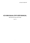
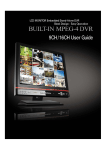
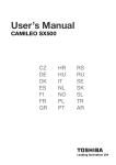
USER’S MANUAL 4CH COLOR SCREEN SPLITTER 4CH .COLOR SPLITTER INDEX 1. MAIN FEATURES AND FUNCTIONS----------------------------------------- 2 2. 4CH. COLOR SPLITTER SPECIFICATION------------------------------------- 3 2-1. REAR PANEL SPEC 2-2. FRONT PANEL SPEC 2-3. CATEGORIZED SPECS 2-4. ELECTRICAL AND PHYSICAL CHARACTERISTICS 3. OUTER APPEARANCE AND FEATURES-------------------------------------- 4 3-1. 4CH. COLOR SPLITTER FRONT 3-2. 4CH. COLOR SPLITTER REAR 3-3. BUTTON FUNCTIONS 3-4. ALARM 4. MENU SETUP--------------------------------------------------------- 7 4-1. BASIC SETUPS 4-2. TIME/DATE SETUP 4-3. CAMERA NAME SETUP 4-4. SEQUENTIAL DISPLAY SETUP 4-5. SPLIT MODE SETUP 4-6. ALARM SETUP 4-7. MOTION DETECTION SETUP 4-8. OTHERS 5. INSTALLATION-------------------------------------------------------- 10 5-1. VIDEO SIGNAL CONNECTION 5-2. VIDEO SIGNAL INPUT/OUTPUT 5-3. ALARM SIGNAL INPUT/OUTPUT 5-4. ALARM PORT 5-5. REMOTE CONTROL PORT 6. INITIAL MODE SETUP--------------------------------------------------- 12 1 4CH .COLOR SPLITTER 1. Main features and functions 4CH. Color Splitter is a high-quality 8ch dual page screen splitter. All-in-one board design and high-density digital components guarantee excellent display quality. 4CH. Color Splitter supports such functions as alarm, buzzer, remote control, motion detection, etc. Main features ◈ ◈ ◈ ◈ ◈ ◈ ◈ ◈ ◈ ◈ ◈ ◈ ◈ ◈ 2,3, or 4 split screens (Real Time Display) High resolution in EIA 720x480 /CCIR 720x576 EIA / CCIR compatible PIP(Picture In Picture) Auto Sequence and Video Loss Auto Skip Motion Detection OSD(On Screen Display) and Time display 1:1(FULL) Screen Freeze Sequential display in PIP Play Back and Zoom(2x) Monitor Output,VCR Input/Output 4 Sensors and 1 Alarm output Parallel port and Serial port(RS-232C) 4CH .COLOR SPLITTER 2 2. 4ch. Color Splitter Specifications 2-1. Rear Panel Name Camera Input Loop Output VCR Input Output No. 4 4 1 1 Type BNC BNC Signal CVBS CVBS Descriptions 1Vpp @75 Ohm Load Auto Load (The same signal as the camera input signal) BNC CVBS 1Vpp @75 Ohm Load Monitor Output VGA Output 2 BNC CVBS 1Vpp @75 Ohm Load 1 DSUB-15 VGA COMPUTER VGA Signer Sensor Input Alarm Output RemoteControl Parallel Serial 4 1 8 1 DB15-3R TTL Drive TR Drive TTL RS-232C Power 1 DC Jack DC12V Power Ground 1 Bolt 3P x 7mm Ground TT, 1K Ohm pull-up Photo-coupler isolation, 30V 50mA The same functions as the front panel functions * Either sensor input or parallel remote control can be used, not both 2-2. Front panel Name Buttons No. 1,2,3,4 4 Freeze/Full Screen /Cursor/Zoom Area Setup SPLIT 1 Split mode selection /Reset in alarm /data change in menu Cameras Descriptions FREEZE 1 All-channel Freeze/ Menu (toggle) SEQUENCE 1 Sequential display / Playback ZOOM 1 Zoom in playback Display Playback 2-3. Categorized Specs Name Time/date Camera Title Switching Sequnce Time Split screen mode Values Descriptions Asia-Euro-US, Three display modes, 24-hour display (On/Off) Disp. ON/OFF 8 Character, Disp. OSD type diplay (English, Number, Special Character) On/Off ON/OFF Sequential channel switching time in Off-99Sec (split mode included, and video loss channel excluded) Automatic sequence in Full/PIP 8 Type 2-way, 3-way, 4-way setup for each channel OSD location 4 Sensor Type OFF-N.O-N.C OSD location setup and OSD ON/Off NO/NC/OFF setup for each channel Alarm Continuation OFF-30Min Alarm continuation time (photo-coupler activation time) Buzzer Continuation OFF-99Sec Buzzer continuation time Video loss detection Yes OSD ON/OFF Motion detection ON/OFF In case of video loss, “ L” sounds. appears on the screen and the buzzer OSD On/Off Motion detection and motion sensitivity setup according to the program-set areas. (ON/Off) 2-4. Electrical and Physical size and characteristics Name Size Descriptions EIA 720x480 60field, 30frame/Sec CCIR 720x576 50field, 25frame/Sec W 210mm x D 200(+10)mm x H 44mm Weight 2.5Kg / 5.5 lbs Resolution Power and power consumption DC12V 0.5A (or DC18V / 0.5A) Operating Temperature -10 C°~ +50 °C / 20~85 % RH / Less than 5 W 4CH .COLOR SPLITTER 3 3. Outer Appearance and Features 3-1. 4ch. Color Splitter Front panel ① ① ② ③ ④ ② ③ ④ CHANNEL 1∼4 Quad mode (4-SPLIT screen) FREEZE / MENU SEQUENCE / PLAY BACK 3-2. 4ch. Color Splitter Rear panel ① ② ③ ④ ⑤ ⑥ ⑦ ⑧ ⑨ ⑩ ① ② ③ ④ ⑤ ⑥ ⑦ ⑧ Video Input (CH. 1-4) Monitor Output1 VCR Input VGA Output Loop Output (CH. 1-4) Monitor Output2 VCR Output Alarm input/output and remote control Power GROUND ⑨ ⑩ 4CH .COLOR SPLITTER 3-3. Button Functions Each button has two functions depending on the way you push them – 1) push or 2) push and hold. ① ② ③ ④ ① FREEZE, FULL SCREEN If you are in quad mode, you can freeze or unfreeze a channel simply by pushing the corresponding channel. You can have a full channel mode for each of CH1~4 by pushing and holding CH1~4. ② SPLIT, RESET(deactivation of alarm and motion) To have a quad view, you should press “ SPLIT” button. You can deactivate the possible event (alarm and motion) by pushing and holding this button. ③ FREEZE(all-channel freeze), MENU If you push the button, all channels freeze. To deactivate the freeze, you push it again. If you push and hold the button, you enter the menu mode. ④ SEQUENCE, PLAY BACK If you push the button, you can have the channels switch at the intervals of transition time (0~99sec) you set. If you have set up PIP for Sequence, only PIP switches in sequential display. If you push and hold the button, you can playback VCR. While you are playing back, you can zoom (2X) in the channel. 5 4CH .COLOR SPLITTER 3-4. Alarm ① Alarm Input and Alarm Output(photo-coupler output) If an alarm signal is received from the sensor, the letter “ A” appears on the screen with an alarm and photo-coupler is activated. The alarm is deactivated after a set amount of time. You can, however, force the alarm to stop by pushing and holding SPLIT (RESET). ② Motion detection(VMD) You can activate the alarm when there’ s a motion within the set area and the letter “ M” appears on the screen with the beep, and the photo-coupler is activated. ③ Video Loss In case of a video loss because of a possible camera malfunction, the letter “ L” appears on the screen with the beep. 6 4CH .COLOR SPLITTER 4. Menu Setup 4-1. Basic setups You push and hold FREEZE to enter the Menu mode. The values set in Menu remain unchanged even after power-off. You can move cursors to set values with the keys as below: You select any menus with the cursors ( ) and enter () to have sub menus. - MAIN MENU1. TIME/DATE 2. CAMERA TITLE 3. AUTO SEQUENCE 4. DISPLAY 5. ALARM SET 6. MOTION DETECTION 7. MISCELLANEOUS Buttons Functions Cursors Enter Key (confirmation) / Enter Submenu Exit / Enter Uppermenu 4-2. Time/Date Setup 1. TIME: Time Setup. 2. DATE: Date Setup. 3. TIME DISPLAY: You can set the time display on or off. 4. DATE DISPLAY: You can set the date display on or off. 5. DATE FORMAT: You can choose any one of three Date formats (ASIA, US, EURO). Date Format: 1) ASIA: yyyy - mm - dd 2) USA : mm - dd - yyyy 3) EURO: dd - mm – yyyy 6. YEAR FORMAT: You can set the year format in two or four digits. (2(yy) or 4(yyyy)) 7. TIME CORRECT: You can set time correction values (seconds) to maintain the most correct time. The set values will be added to or subtracted from the current time every day or month. - TIME/DATE – 1. TIME(HH:MM:SS) : 12:25:30 2. DATE(YY-MM-DD):2001-01-09 3. TIME DISPLAY : ON 4. DATE DISPLAY : ON 5. DATE FORMAT : ASIA 6. YEAR FORMAT : 4DIGIT 7. TIME CORRECTION: DAY+00SEC 7 4CH .COLOR SPLITTER 4-3. Camera Name Setup TITLE : CAM1 123456789AB CDEFGHIJKLMN OPQRSTUVWXYZ /., () : # To change the camera name, you select any channel using cursors and push the enter button (). Now you can choose characters for the channel you have selected. You move cursors ( or ) to place the cursor on the character you’ d like to choose, and then you push the enter button (). You repeat the same process until you are finished. 4-4. Sequential Display Setup 1~5: You set the channel switching time for the Sequence mode. If you set a camera off for auto sequence, it does not appear in the Sequence mode. 6. LOSS AUTO SKIP: If it’ s ON, video loss channels do not appear in sequence mode. If it’ s OFF, video loss channels appear in sequence mode. 7. SEQUENCE MODE: If you select FULL, PIP does not appear when it switches. If you select PIP, PIP appears when it switches. 8. PIP SEQUENCE: If you select MAIN, the channel in the background switches, not PIP. If you select PIP, only PIP switches, not the channel in the background. (To have PIP switch, you have to set the menu number 7, SEQUENCE MODE, in PIP mode beforehand.) - AUTO SEQUENCE 1. CH1 : 03s 2. CH2 : 03s 3. CH3 : 03s 4. CH4 : 03s 5. QUAD : 03s 6. LOSS AUTO SKIP : ON 7. SEQUENCE MODE : FULL 8. PIP SEQUENCE : PIP 4-5. Split Mode Setup - DISPLAY 1. MULTISCREEN MODE -QUAD2. OSD POSITION : A,B,C,D 3. BORDER TYPE : A,B,C 1. MUTISCREEN MODE: You select any one of the following split modes. QUAD 2WAY-1 QUAD-1 QUAD-2 3WAY-1 3WAY-2 3WAY-3 3WAY-4 2. OSD POSITION: You decide where you will place the OSD. 01/30 CAM 1 CAM 2 CAM 1 01/30 CAM 1 CAM 2 CAM 2 01/30 01/30 CAM 4 CAM 3 CAM 4 CAM 2 CAM 1 CAM 3 CAM 4 01/30 10:01 01/30 10:01 CAM 3 CAM 4 CAM 3 3. Boarder Type: You select one of three border type options (black, grey, or no border). 8 4CH .COLOR SPLITTER 4-6. Alarm Setup - ALARM 1. 2. 3. 4. 5. 6. 7. CH1 : N.O CH2 : N.O CH3 : N.O CH4 : N.O ALARM OUTPUT TIME :01min ALARM BUZZER TIME : 3sec VIDEO LOSS BUZZER : ON 1~4: You decide the sensor input type. N.O: It alarms when the contact is closed. N.C: It alarms when the contact is open. OFF: No alarm is set 5. ALARM OUTPUT TIME: OFF ~ 30 MIN When the alarm sounds (photo-coupler is activated), the status of alarm or motion maintains its status for the set amount of time. 6. ALARM BUZZER TIME: OFF ~ 59 SEC You set the amount of time for the alarm to sound. 7. VIDEO LOSS BUZZER: You can set the video loss buzzer on or off. 4-7. Motion Detection Setup 1~4: You can set the motion detection area and motion sensitivity for each channel. You can deactivate it (OFF) if you are not going to use it. - MOTION 1. 2. 3. 4. 5. 6. DETECTION Cell size: 16X12 CH1 : OFF / AREA CH2 : OFF / AREA CH3 : OFF / AREA CH4 : OFF / AREA MOTION SENSITIVE : 10 MOTION MODE : QUAD Pink: cursor Red: detected area Green: motion setup 5. MOTION SENSITIVE: You set the motion sensitivity. As the sensitivity gets closer to ‘ 1’ , the more sensitive it becomes. 6. MOTION MODE: When motion is detected on a certain channel, the channel becomes a full screen in FULL mode. In QUAD mode ‘ M’ appears on the motion-detected channel to identify the channel. 4-8. Others - MISCELLANEOUS - 1. REMOCON ID : OFF 2. OSD : OFF 3. COLOR KILL : OFF 4. ALARM REMOTE : REMOTE SELECT 1. REMOTE CONTROL ID: When controlling more than one device using RS232C, you assign different device numbers to each device to control them remotely. 2. OSD: When OSD is in off mode, no OSD appears except MENU. 3. COLOR KILL: You turn it on when using B/W monitors. 4. ALARM REMOTE SELECT: Eight D-SUB terminals in the rear panel can either be used as remote controllers or sensor inputs. 9 4CH .COLOR SPLITTER 5. Installation 5-1. Video Signal Connection 5-2. Video Signal Input/Output PROCESSING CIRCUIT BNC BNC 75 1 1 2 3 2 CAMERA INPUT OUT PUT T O MONITOR 2Vpp 75 75 ESD PROTECTOR 3 4 LOOP OUT ESD PROTECTOR 5-3. Alarm Signal Input/Output TERMIANL TERMIANL PROCESSING CIRCUIT 1 3 4 V CC 2 +5 V C 1K Q1 S IN 10 0K GND E 75 P HOT O COUP LE R SENSOR INPUT 5V 0V > 100mSec ON OFF ALARM OUTPUT Duration: Alarm Output Time (Prograrm Value) NOTE: Designated connectors should be used for alarm connection. Recommend Input/output voltage should be used. Otherwise, it may cause a malfunction . 10 4CH .COLOR SPLITTER 5-4. Remote Control Port ① The following shows the remote control ports including serial and parallel ports. G S4 S3 S2 S1 G S8 S7 S6 S5 RX TX G E C ` 11 6 The following shows that the pin layout of parallel remote control ports and the corresponding functions . D-S UB 15 P V GA Keyboard Layout for remote control port 11 S EQUENCE CH4 GND TX RX S PL IT GND FRE EZE S1 S2 S3 S4 GND S5 S6 S7 CH3 1 2 3 4 5 6 7 8 9 10 11 12 13 14 15 CH2 | 1 10 15 CH1 ② 5 4CH .COLOR SPLITTER 5-5. RS-232C Remote control CODE ① STAND ALONE: You can use the following three codes when using one serial port. You should check MULTI REMOTE ID off after entering MISCELLANEOUS in menu. STX ② OP CODE ETX MULTI COMMUNICATION: If you want to control more than one multiplexer with one port, you should have HEADER codes to distinguish the multiplexers from one another. The maximum number of multiplexers to be combined is 16. You have to set each multiplexer with different MULTI REMOTE ID from 1~16, after entering MISCELLANEOUS in menu. SOH HEADER STX OP CODE ETX ③ The following codes show each of their functions. CONTROL CODE INTIAL SOH STX ETX CODE 01 02 03 HEADER CODE AO AF 1D No 1 16 OP CODE CODE 90 91 92 93 94 95 96 97 98 99 9A 9B 9C FUNCTION CH1 CH2 FREEZE CH3 CH4 SPLIT FREEZE SEQUENCE CODE 80 81 82 83 84 85 86 87 88 89 8A 8B FUNCTION CH1 CH2 FULL CH3 CH4 SPLIT MENU PLAY BACK 6. Initial Mode Setup After a possible malfunction or repair of a device, the status of inner programs might change. In this case, you can retrieve the initially setup mode. To go back to the initially setup mode, you turn the power on and off while you keep pushing the following button depending on the model and scanning mode. MODEL 4ch color splitter NTSC PAL FREEZE BUTTON 12 WARRANTY AND LIABILITY WARRANTY OUR COMPANY WARRANTS THAT THE GOODS ARE FREE FROM DEFECTS IN MATERIAL AND WORKMANSHIP AND WILL SUBSTANTIALLY CONFORM TO OUR COMPANY’ S PUBLICLY AVAILABLE SPECCIFICATIONS DURING THE PERIOD OF ONE YEAR FROM THE DATE OF PURCHASE. EXTENT OF LIMITED WARRANTY THIS LIMITED WARRANTY DOES NOT COVER THE DAMAGES DUE TO EXTERNAL CAUSES, INCLUDING ACCIDENT, PROBLEM WITH ELECTRICAL POWER, AND USAGE NOT IN ACCORDANCE WITH PRODUCT INSTRUCTIONS, MISUSE, NEGLECT, ALTERATION, REPAIR, IMPROPER INSTALLATION, OR IMPROPER TESTING. LIMITATIONS OF LIABILITY OUR COMPANY’ S RESPONSIBILITY UNDER THIS OR ANY OTHER WARRANTY, IMPLIED OR EXPRESSED, IS LIMITED TO REPAIR, REPLACEMENT OR REFUND, AS SET FORTH ABOVE. OUR COMPANY IS NOT RESPONSIBLE FOR DIRECT, SPECIAL, INCIDENTAL OR CONSEQUENTIAL DAMAGES RESULTING FROM ANY BREACH OF WARRANTY OR UNDER ANY OTHER LEGAL THEORY INCLUDING, BUT NOT LIMITED TO, LOST PROFITS, DOWNTIME, GOODWILL, DAMAGE TO OR REPLACEMENT OF EQUIPMENT AND PROPERTY, AND ANY COSTS OF RECOVERING, REPRODUCING ANY DATA STORED IN OR USED WITH A SYSTEM CONTAINING THE GOODS. INSTRUCTIONS 1. READ ALL SAFETY AND OPERATING INSTRUCTIONS BEFORE OPERATING THIS PRODUCT. 2. RETAIN THE SAFETY AND OPERATING INSTRUCTIONS FOR FUTURE REFERENCE. 3. UNPLUG THE PRODUCT BEFORE CLEANING. DO NOT USE LIQUID OR AEROSOL CLEANERS. USE A DAMP CLOTH FOR CLEANING. 4. ONLY MANUFACTURER-RECOMMENDED ATTACHMENTS ARE TO BE USED. OTHERWISE, IT MAY RESULT IN THE RISK OF FIRE, ELECTRIC SHOCK OR INJURY. 5. KEEP THE PRODUCT AWAY FROM LIQUID OR ANY OTHER TYPE OF MOISTURE. 6. DO NOT PLACE THIS PRODUCT ON AN UNSTABLE CART, STAND OR TABLE. OTHERWISE, IT MAY CAUSE SERIOUS INJURY TO A CHILD OR ADULT AND SERIOUS DAMAGE TO THE PRODUCT. ANY MOUNTING OF THE PRODUCT SHOULD FOLLOW THE MANUFACTURER'S INSTRUCTIONS AND SHOULD USE A MOUNTING ACCESSORY RECOMMENDED BY MANUFACTURER. 7. THE PRODUCT SHOULD BE OPERATED ONLY FROM THE TYPE OF POWER SOURCE INDICATED ON THE LABEL. 8. DO NOT PUT ANYTHING ON THE POWER CORD AND PREVENT IT FROM ANY TYPE OF ABUSE. 9. IF THE PRODUCT IS NOT USED FOR A LONG TIME, PLEASE UNPLUG IT FROM THE POWER SUPPLY AND DISCONNECT IT FROM OTHER EQUIPMENT. THIS WOULD PREVENT FROM DAMAGE TO THE PRODUCT DUE TO LIGHTING AND POWER-LINE SURGES. 10. DO NOT OVERLOAD WALL OUTLETS AND EXTENSION CORDS TO PREVENT FROM THE RISK OF FIRE OR ELECTRIC SHOCK. 11. DO NOT INSERT ANY KIND OF OBJECTS INTO THE PRODUCT. 12. DO NOT TOUCH ANY PARTS INSIDE FOR REPAIR. THERE ARE NO USER SERVICEABLE PARTS. IT MAY EXPOSE YOU TO DANGEROUS VOLTAGES OR OTHER HAZARDS. REFER TO QUALIFIED PERSONNEL FOR REPAIR. 13. REPLACEMENT PARTS ARE TO BE PROVIDED BY THE AUTHORIZED TECHNICIANS DESIGNATED BY THE MANUFACTURER. THE USE OF UNAUTHORIZED SUBSTITUTE COMPONENTS MAY RESULT IN FIRE, ELECTRIC SHOCK OR OTHER HAZARDS. 14. ASK THE SERVICE TECHNICIAN AS FOR SAFETY CHECK UPON COMPLETION OF ANY SERVICE OR REPAIR OF THE PRODUCT.