1
Draft for Public Comment
Number
SR 50-2:2010
Title
Code of practice for building services – Part 2: Solar
panels
This document gives general guidelines for design, installation and
commissioning of solar heating systems, in single dwellings.
Enquiry period: 28th May 2010 to 27th August 2010
Readers are warned that this draft is subject to ongoing
development and change
Please send your comments on the comments sheet available on
www.NSAI.ie to:
[email protected] or
NSAI
1 Swift Square,
Northwood,
Santry
Dublin 9
Date: 2010-05
pr SR 50-2:2010
Code of practice for building services — Part 2 Solar panels
pr SR 50-2:2010 (E)
2
pr SR 50-2:2010 (E)
Contents
Page
Introduction.........................................................................................................................................................4
1
Scope ......................................................................................................................................................4
2
Normative references............................................................................................................................7
3
3.1
3.2
3.2.1
3.2.2
3.3
3.3.1
3.3.2
3.3.3
3.3.4
3.3.5
3.3.6
3.3.7
3.3.8
3.3.9
3.4
Solar heating systems – General requirements...............................................................................10
General .................................................................................................................................................10
Minimum specifications......................................................................................................................10
Technical specifications .....................................................................................................................10
Minimum provisions for labelling, commissioning and documentation .......................................10
Safety Considerations.........................................................................................................................10
General .................................................................................................................................................10
Location/Access ..................................................................................................................................11
Layout of pump station and cylinder ................................................................................................12
Risk of bacterial growth/legionella ....................................................................................................12
Unvented hot water storage systems................................................................................................12
Existing buildings................................................................................................................................13
Pressure relief valves..........................................................................................................................13
Differential thermostatic control........................................................................................................13
Lightning protection............................................................................................................................14
Materials ...............................................................................................................................................14
4
4.1
4.2
4.3
Solar collectors - Requirements ........................................................................................................16
Positioning of collectors for maximum solar efficiency .................................................................16
Behaviour in Relation to Fire .............................................................................................................16
Structural Performance.......................................................................................................................17
5
5.1
5.2
5.3
Solar collectors – Design details and workmanship .......................................................................21
General .................................................................................................................................................21
Weathering and Drainage Requirements ..........................................................................................21
High Temperature Conditions............................................................................................................22
6
Solar collectors – Design life .............................................................................................................23
7
7.1
7.2
7.3
Installation............................................................................................................................................24
General .................................................................................................................................................24
Risk Assessment.................................................................................................................................24
Installation Procedure.........................................................................................................................25
8
8.1
8.2
8.3
Commissioning and Maintenance .....................................................................................................27
Commissioning....................................................................................................................................27
Maintenance.........................................................................................................................................27
User Manual .........................................................................................................................................28
9
Locating Reference Material ..............................................................................................................29
Annex A (informative) Extract of Table 32, DoEHLG/SEAI publication Heating and domestic hot
water systems for dwellings – Achieving compliance with Part L 2008........................................30
Annex B (informative) Sample wind load calculation for solar collectors..................................................32
B.1
Determining the Design Wind Load...................................................................................................32
B.2
Sample wind load calculations for roof-mounted collector............................................................33
B.3
Sample wind load calculations for in-roof collector........................................................................36
Annex C (informative) Sizing of solar collector and storage........................................................................38
3
pr SR 50-2:2010 (E)
Introduction
These guidelines have been established to elaborate on the requirements for solar water heating systems, not
directly addressed by Part L of the Building Regulations.
The guidelines are intended to assist providers and specifiers of solar water heating systems, in the
interpretation of the requirements and to provide guidance as to how the requirements should be addressed.
This document has been developed by a working group of representatives from:
⎯ NSAI Agrément
⎯ Department of Environment, Heritage and Local Government (DoEHLG)
⎯ Sustainable Energy Authority of Ireland (SEAI)
Emphasis is on general principles, and not on detailed aspects of particular systems. As the construction
industry becomes more familiar with all aspects of solar heating systems, technical issues may arise requiring
the document to be reviewed.
1
Scope
This document gives general guidelines for design, installation and commissioning of solar heating systems, in
single dwellings, where:
⎯ The solar heating system is incorporated into, and the solar collector is an integrated or stand alone
element of, the external building envelope
⎯ The solar heating system is designed as the primary or auxiliary water heating system
⎯ The solar collector area is less than 20m2 and the solar heated water storage is less than or equal to
1000 litres.
This document gives guidance on:
⎯ Design, installation, commissioning and workmanship requirements for solar collectors and their
associated fittings and accessories
⎯ Structural, constructional and weathertightness aspects of the solar collector installation, including
resistance to rain, wind, frost, fire resistance and durability
⎯ Use of solar water heating systems incorporating vented and unvented water storage
⎯ Environmental and health and safety issues.
Solar collectors covered by this document include flat plate collectors and evacuated tube collectors, either
integrated into the roof structure or fitted on the roof.
4
pr SR 50-2:2010 (E)
The solar collectors listed on the SEAI registered product lists have been tested in accordance with
EN 12975-1 and EN 12975-2 and are assumed to be proper materials for the purposes of Part L of the
Building Regulations (see Section 1.2.6 of Building Regulations Technical Guidance Document (TGD) L).
Guidance on the assessment of solar heating systems against the requirements of Part L of the Building
Regulations is given in DoEHLG/SEAI publication Heating and domestic hot water systems for dwellings –
Achieving compliance with Part L 2008 and Appendix H of the DEAP manual.
Guidance on the mechanical and plumbing design and installation of solar heating systems is given in
EST document CE131 Solar water heating systems – Guidance for professionals, conventional indirect
models, and CIBSE document Solar heating – Design and installation guide.
It should be noted that the dwelling as a whole, incorporating these products must comply with all parts of the
Building Regulations. Issues of particular relevance where, for example, roof mounted solar collectors are
fitted may include weathertightness, fire safety, structural safety etc. Third party certification bodies, e.g. NSAI
Agrément, are available to assess compliance with all parts of the Building Regulations.
Applications for space heating, heating of swimming pools and installations onto facades of buildings are
outside the scope of this document.
5
pr SR 50-2:2010 (E)
NOTE
Fitting the expansion vessel in the orientation above is considered best practice for solar heating systems
Figure 1 — Example of a solar heating system schematic (Flat plate collector)
6
pr SR 50-2:2010 (E)
2
Normative references
The documents listed below contain provisions, which, through reference in this text, constitute provisions of
this document. For undated references, the latest edition of the cited publication applies, together with any
amendments.
Irish Building Regulations and Technical Guidance Documents Parts A to M.
Heating and Domestic Hot Water Systems for Dwellings – Achieving compliance with Part L 2008 Section 9
Solar Water Heating.
Safety, Health and Welfare at Work (Construction) Regulations.
Electro Technical Council of Ireland (ETCI) publication ET 207 Guide to the National Rules for Electrical
Installations as Applicable to Domestic Installations.
SEAI Dwelling Energy Assessment Procedure (DEAP) Manual.
EST document CE131 “Solar water heating systems – Guidance for professionals, conventional indirect
models”.
CIBSE document “Solar heating – Design and installation guide”.
National Guidelines for the Control of Legionellosis in Ireland (HPSC, 2009).
The Management of Legionnaire’s Disease in Ireland (NDSC, 2002).
BRE Digest 489 Windloads on roof-based photovoltaic systems.
BRE Digest 495 Mechanical installation of roof-mounted photovoltaic systems.
I.S. S.R. 50
Code of practice for plumbing and heating (currently being drafted).
I.S. ICP 2
Code of practice for slating and tiling.
I.S. 193
Timber trusses for roofs.
I.S. 444
The use of structural timber in buildings.
I.S. EN 485-1
and delivery.
Aluminium and aluminium alloys: Sheet, strip and plate. Technical conditions for inspection
I.S. EN 516 Prefabricated accessories for roofing – Installations of roof access – Walkways, treads and steps.
I.S. EN 517 Prefabricated accessories for roofing – Roof safety hooks.
I.S. EN 795 Protection against falls from a height – Anchorage devices – Requirements and testing.
I.S. EN 837-1
and testing.
Pressure gauges – Bourdon tube pressure gauges – Dimensions, metrology, requirements
I.S. EN 1490 Building valves – Combined temperature and pressure relief valves – Tests and requirements.
I.S. EN 1991-1-1 Eurocode 1 – Actions on structures – General actions – Densities, self-weight, imposed
loads for buildings.
I.S. EN 1991-1-4 Eurocode 1 – Actions on structures – General actions – Wind actions.
7
pr SR 50-2:2010 (E)
I.S. EN 1995-1-1 Eurocode 5 – Design of timber structures – General – Common rules and rules for buildings.
I.S. EN 12975-1 Thermal solar systems and components – Solar collectors – General requirements.
I.S. EN 12975-2 Thermal solar systems and components – Solar collectors – Test methods.
I.S. EN 12976-1 Thermal solar systems and components – Factory made systems – General requirements.
I.S. EN 12976-2 Thermal solar systems and components – Factory made systems – Test methods.
I.S. ENV 12977-1 Thermal solar systems and components – Custom Built systems – Part 1:General
requirements
I.S. ENV 12977-2
Thermal solar systems and components - Custom built systems – Part 2:Test methods
I.S. ENV 12977-3
Thermal solar systems and components - Custom built systems – Part 3: Performance
characterization of stores for solar heating systems
I.S. EN 12897
Water supply – Specification for indirectly heated unvented (closed) storage water heaters.
I.S. EN 14336
systems.
Heating systems in buildings – Installation and commissioning of water based heating
I.S. EN 14437
Determination of the uplift resistance of installed clay or concrete tiles for roofing – Roof
system test method.
I.S. EN 60730-2-11
energy regulators
I.S. EN 62305
Automatic electrical controls for household and similar use. Particular requirements for
Protection against lightning.
I.S. EN ISO 9488 Solar energy – Vocabulary.
prEN 15601 Hygrothermal performance of buildings – Resistance to wind driven rain of roof coverings with
discontinuously laid small elements – Test method.
ISO 9553
collectors.
Solar energy – Methods of testing preformed rubber seals and sealing compounds used in
ISO/TR 10217
Solar energy water heating systems guide.
BS 476-3
Fire tests on building materials and structures – Classification and method of test for external fire
exposure to roofs.
BS 1494-1
coverings.
Specification for fixing accessories for building purposes – Fixings for sheet, roof and wall
BS 1710 Identification of pipelines and services.
BS 5250 Code of practice for control of condensation in buildings.
BS 5534 Code of practice for slating and tiling (including shingles)
BS 5918 Code of practice for solar heating systems for domestic hot water.
BS 6283-2 Safety and control devices for use in hot water systems - Specifications for temperature relief
valves for pressures from 1 bar to 10 bar
8
pr SR 50-2:2010 (E)
BS 6375 Performance of windows and doors – Classification for weathertightness and guidance on selection
and specification.
BS 7206 Specification for unvented hot water storage units and packages
BS 7543 Guide to durability of buildings and building elements, products and components.
9
pr SR 50-2:2010 (E)
3
Solar heating systems – General requirements
3.1 General
A solar heating system generates heat by means of solar collectors, either flat plate or evacuated tubes, which
absorb solar radiation energy and converts it to thermal energy. The part of a solar collector which converts
the solar energy into thermal energy is called the absorber. The absorber is usually in the form of a plate with
a special layer coating, where a high level of solar energy can be captured with low heat losses due to
emission of the resulting heat energy from the absorber. The absorber is connected internally to small fluid
carrying pipes through which the heat transfer fluid passes.
The collector usually has a transparent cover, which allows solar energy to enter and helps reduce heat
losses by convection. An insulated enclosure provides structural integrity and reduces losses from conduction.
The solar collectors are connected to the domestic hot water (DHW) system and/or the heating system in the
dwelling by means of suitable pipe work which contains the heat transfer fluid. Most commonly, the heat
transfer fluid used is a mixture of water and glycol (anti-freeze).
3.2
3.2.1
Minimum specifications
Technical specifications
Solar heating collectors should be fully tested and independently certified to I.S. EN 12975-1 and
I.S. EN 12975-2 which specify requirements and test methods for solar collectors.
Solar heating systems should be fully tested and independently certified to comply with:
⎯ I.S. EN 12976-1, I.S. EN 12976-2 , I.S. ENV 12977-1, I.S. ENV 12977-2 and I.S. ENV 12977-3 as
appropriate;
⎯ DoEHLG/SEAI publication Heating and domestic hot water systems for dwellings – Achieving compliance
with Part L;
⎯ Building Regulations.
The solar collectors listed on the SEAI registered product lists have been tested in accordance with EN
12975-1 and EN 12975-2 and are assumed to be proper materials for the purpose of Part L of the Building
Regulations (see Section 1.2.6 of Building Regulations TGD L 2007). Third party certification bodies, e.g.
NSAI Agrément, are available to assess compliance with all parts of the Building Regulations.
It is recommended that solar collectors should carry the Solar Key Mark.
3.2.2
Minimum provisions for labelling, commissioning and documentation
Provisions for the solar collector and hot water store should be in accordance with Section 9 Table 32 of
DoEHLG/SEAI publication Heating and domestic hot water systems for dwellings – Achieving compliance with
Part L (see Appendix A).
3.3 Safety Considerations
3.3.1
General
The solar heating system should be designed, installed and commissioned to ensure the levels of risk
associated with all aspects of the solar collector installation and operation are acceptable. Guidance on
addressing the safety requirements associated with mechanical installation, operation and maintenance of the
system is given in EST document CE131 and CIBSE document Solar heating – Design and installation guide.
10
pr SR 50-2:2010 (E)
All aspects of the work should be carried out by persons qualified to carry out such work to ensure the
appropriate levels of safety are achieved.
The design, installation and commissioning of solar thermal installations should be carried out by a person
qualified to carry out such work in accordance with clause 1.2.7 of the Building Regulations TGD L. A suitably
qualified installer must have achieved certification from an accredited training course in each of the technology
areas they wish to work in. SEAI, in conjunction with the Renewable Energy Installer Academy (REIA), has
developed training courses for each technology, and these courses are FETAC accredited.
A risk assessment should be prepared before work starts, to identify and show how the risks identified will be
controlled. Section 7.2 gives details on the potential risks that must be covered by a risk assessment.
Safety requirements particular to elements of the system are given in product specific standards, e.g.
EN 12976-1, EN 12976-2, EN 12977-1, EN 12977-2 and EN 12977-3.
All construction work related to the installation of solar collectors into or onto the building fabric should be
performed to Safety Health and Welfare (Construction) at Work Regulations. Specialised access equipment,
including eaves-level platforms, steel scaffold or towers, cranes or hoists may be required during installation.
Recommendations for a pre-installation risk analysis are provided in Section 7.2, which can be expanded
upon relevant to the specific site/installation.
All electrical work must be in accordance with ETCI regulations and carried out by persons suitably qualified to
carry out such work. A non-switchable fused spur with LED should be used for the system.
Operation and safety of auxiliary heating systems should not be compromised and should be in accordance
with relevant standards.
All pipework should be clearly marked in accordance with BS 1710.
3.3.2
Location/Access
The solar heating system shall be installed so as to:
⎯ provide reasonable and safe access for maintenance, cleaning, repair or replacement. Consideration
should be given to building height, site exposure (including impact), relative location of conservatories,
power/phone lines, porches, skylights, dormers etc.
⎯ provision of a roof ladder or a safety harness anchorage point for use during inspection/maintenance may
need to be considered.
⎯ avoid compromising access to any existing equipment, e.g. mechanical or electrical.
⎯ avoid compromising the operation of existing doors, windows etc.
⎯ limit risk of components becoming detached or falling off.
⎯ avoid compromising the fire safety of the building itself or adjoining buildings (see Appendix C).
⎯ minimise and withstand the pressures due to wind loading/suction.
⎯ include provision for access within the roof spaces for maintenance of the system. Where necessary,
walkways may need to be constructed to offer safety and protection.
⎯ for integrated (in-roof) collectors, a loft space should be provided behind the collectors for accessing the
pipe connections and/or replacing temperature sensors.
11
pr SR 50-2:2010 (E)
3.3.3
Layout of pump station and cylinder
⎯ consideration should be given to space requirements of hot water storage systems at the design stage.
⎯ all safety features of the system should have sufficient clear space for inspection, maintenance and/or
replacement.
⎯ the pump station assembly which houses the mechanical safety controls, components and fittings should
be clearly visible in the store, be readily accessible and not concealed or obstructed by cylinders, vessels,
shelving or similar.
⎯ a good practice layout should be made available with each solar hot water system showing position of
components (pump station, cylinder, expansion vessel etc.) and minimum clear space recommended on
plan for all access requirements.
⎯ it may be necessary to provide a dedicated service room for the solar hot water system including pump
station, cylinder and related components.
⎯ consideration should be given to the load bearing capacity of the solar cylinder.
3.3.4
Risk of bacterial growth/legionella
The solar heating system should be designed so as to prevent the risks associated with bacterial growth, low
water flow rates and scale formation whilst preventing risk of scalding due to high water temperatures.
In order to reduce the risk of colonization of a water system the temperature of cold water in pipes and
cisterns should not exceed 20oC, and hot water should be stored and distributed at a temperature of not less
than 60oC with a temperature at the discharge point of 50oC after one minute. Systems should be designed
and operated to provide appropriate temperature control of water storage. Information and guidance should
be provided to the homeowner on the correct operation of these systems during normal operation and after
periods of non use. For further guidance, refer to National Guidelines for the Control of Legionellosis in
Ireland (HPSC, 2009) and The Management of Legionnaires’ Disease in Ireland (NDSC, 2002).
Cold and hot water pipe work should be as short as practicable, especially where it only serves infrequently
used taps and fittings. In all cases minimum hot and maximum cold water temperatures should be reached at
all draw-off points after a maximum period of one minute running at full flow. Due consideration should be
given to the selection of braided or flexible hoses and the suitability of materials in contact with water.
Measures shall be taken in the design and installation of cold and hot water systems to prevent the
colonization of the system with legionella. These shall include the avoidance of:
⎯ stagnation of water in pipes, cisterns and other storage vessels;
⎯ water temperatures in the range of 20oC to 45oC;
⎯ use of materials that can harbour or provide nutrient for bacteria and other organisms, inside cisterns.
3.3.5
Unvented hot water storage systems
Where the solar heating system incorporates unvented hot water storage not exceeding 500 litres and 45kW
power input, additional safety requirements will apply. As a minimum, the unvented hot water storage system
should:
⎯ be designed and installed by a person qualified to carry out such work.
⎯ be an appropriate package which satisfies the requirements of the Building Regulations Part D, and has
third party certification to EN 12897.
12
pr SR 50-2:2010 (E)
⎯ be provided with a minimum of two temperature activated safety devices, capable of preventing the
temperature of stored water reaching 100oC at any time, on direct and indirect systems, i.e.
⎯
a non self resetting thermal cut-out to EN 1490.
⎯
one or more temperature relief valves to BS 6283-2
NOTE
Other safety devices should provide an equivalent degree of safety in preventing temperature of stored water
o
exceeding 100 C.
⎯ have temperature relief valves located directly on the storage vessel, sized to give a discharge rating
measured in accordance with BS 6283-2 Appendix F or BS 6283-3 Appendix G, at least equal to the
power input to the water. Each valve should discharge via a short length of metal pipe, not less than the
outlet size of the relief valve, to a manifold sized to accept total discharge via a vertical metal tun-dish (to
provide an air-break), sited as close as possible to the relief valve (maximum 500 mm).
⎯ for indirect heating systems, a non-self-resetting thermal cut-out should be fitted. This should be wired up
to a motorised valve, or other suitable device to shut off the flow to the primary heater (and be approved
as referenced above).
⎯ ensure hot water is discharged from safety devices and conveyed in pipe work to where it is visible but
causes no danger to persons in or around the building.
3.3.6
Existing buildings
A site visit is required in order to inspect roof voids, the roof condition and clearances for equipment.
Externally, the terrain should be checked for stability as well as above for loose roof tiles and overhead cables,
etc. Heights over two storeys should be approached with particular caution. Consideration should be given to
the load bearing capacity of the cylinder, and to the space required to house the solar cylinder, pump station
etc.
3.3.7
Pressure relief valves
Solar hot water system pressure relief valves should be routed to a vessel made of suitable material capable
of withstanding the high temperature of the fluid, so as to cause minimum damage and to prevent any safety
risks. Local authority approval should be sought if considering direct discharge to drainage system.
All safety control valves should be readily accessible and verifiable in operation, particularly during
commissioning and maintenance.
The requirement to store primary circulation fluid temporarily (typically in hot water cylinder cupboard) may
occur for ‘top up’ purposes or to facilitate a pressure discharge from the solar primary circuit. Where this
occurs, the fluid should be safely stored, e.g. at high level, in a secure transparent locked container, properly
labelled, resistant to high temperature discharge and access controlled to prevent unauthorised removal or
use. Safety signage should be considered within the store, reflecting the potential risks.
Solar heating system pipe work and components may reach temperatures in excess of 1500C under full
stagnation conditions. Consideration should be given to the routes taken by the primary solar pipe work, to
restricting occupant contact, identification markings, and associated risks to adjacent materials or those in
direct contact.
3.3.8
Differential thermostatic control
Solar heating systems should have a Differential Thermostatic Control (DTC) or similar device that can
automatically check for errors/incorrect value readings and give a clear warning of malfunction. Simple
counters of time, volume, power or energy alone are not sufficient for warning of malfunction.
13
pr SR 50-2:2010 (E)
An automatic audible or flashing light warning device to indicate critical malfunction is recommended that
should also allow rapid diagnosis of error.
Predetermined system checks, selected by a commissioning person qualified to carry out such work, are
programmed into the differential pump controller or similar device. These checks are typically based on
temperature, but pressure and/or circulation rates could also be used to trigger an error indicator.
The solar heating system controls should have the capability to provide an accurate readout of the
temperatures of the absorber, solar pre-heat store and auxiliary domestic hot water (DHW) store. This will
typically require the provision of 3 no. temperature sensors: one at the collector, one at the top of the cylinder
and one at the bottom of the cylinder. It is important that key system functions can be monitored to determine
potential performance losses or problems.
The DTC for the solar hot water system should be located in a prominent location that is readily accessible
and frequently occupied. Recommended location for the DTC is on the landing outside the solar store,
generally fixed not less than 1,5 m above floor level. The DTC and function display should be readily visible at
all times with clear access and not concealed or obstructed. Where the DTC is located inside the solar store,
it must be fitted with an audible alarm.
Where the auxiliary heat controls allow, particularly for electric immersions, an immersion timer with LED
switch should be sited beside the DTC. Their location as described above will encourage monitoring of the
solar system temperatures and enable prompt control of the auxiliary heating (by manual or timed cycle/s).
This should contribute to the efficient and safe use of the system.
Using a DTC, it is possible to modulate pump speed in relation to temperature and minimise parasitic losses.
The DTC ‘interlock’ should allow precise adjustments of pump switching on/off points, providing a readout to
aid commissioning and fault detection. A temperature interlock should ensure that the solar system cannot
normally transfer useful heat outside the insulated building envelope. Pumps and controls should be in the
normally heated area of a house. Advanced DTCs use temperature linked speed control of the circulating
pump to maintain higher efficiency heat transfer. It is recommended that the controller should count the
number of operating pump hours for maintenance purposes.
A solar primary system should include a manual override to engage circulation for commissioning in all
weather conditions with a means of accurately indicating primary circulation rate.
Signage fixed in a prominent location close within the pre-heat store is recommended. Signage should
contain details of installers (plumber, electrician etc.), person that commissioned the system, their contact
details, key maintenance requirements, next service, warning of high temperatures to solar components,
advice on control of access to the store etc.
3.3.9
Lightning protection
The risk of property damage or loss of life due to lightning is relatively low in Ireland for domestic properties.
Installation of solar heating systems in domestic properties does not generally increase the level of risk,
particularly as collectors tend to be located below ridge level and are not higher than the chimney. However,
the risk of lightning should be assessed for individual buildings in accordance with I.S. EN 62305. In general,
where a building requires specific lightning protection, the solar collector should be connected to the lightning
protection system.
As a minimum, all pipework should be bonded in order to avoid electrical potential differences. The flow and
return pipes to the solar collector should be fitted with earth clamps, connected to the earthing system of the
house, using an earth bonding cable of minimum 10 mm2. A diode for over-voltage protection should also be
provided to the control panel to limit potential damage from lightning.
3.4 Materials
Materials should comply with Building Regulations TGD D.
14
pr SR 50-2:2010 (E)
The temperatures and pressures experienced by some components may be significantly in excess of normal
domestic operating temperatures (150oC and greater). In addition, consideration should be given to roofing
materials in contact with such components.
All materials and components should:
⎯ be durable for the required design life;
⎯ be capable of withstanding the thermally induced, structural, impact and environmental stresses imposed
during the design life;
⎯ have adequate resistance to wind, rain, impact, heat aging, air pollutants, high humidity, steam, UV
exposure and corrosion (including internal), ozone, salt spray, rodent attack, heat transfer fluid, especially
when in contact with dissimilar metals;
⎯ have adequate resistance to fire.
Guidance for specification of roofing materials is given in I.S. ICP 2. Particular care should be taken to ensure
that solar collector components or roofing materials subject to extreme temperatures (pipe work, welded
connections, insulation, roofing felt etc.) have been designed or selected to function for the expected
temperature range over the design life. Any exposed insulation should be resistant to high temperatures, UV
degradation and be non-water absorbent (closed cell).
Verification of satisfactory performance of the above criteria can be achieved by NSAI Agrément certification
or equivalent, as defined in Part D of the Building Regulations.
Guidance for materials used in hot water systems is given in I.S. SR 50.
Approved fluids, specified by the manufacturer, should contain anti-corrosion inhibitors and anti-freeze. Motor
vehicle anti-freeze should not be used.
All waste antifreeze and corrosion inhibitors should be collected and disposed of in accordance with national
and local regulations, and material safety data sheets.
15
pr SR 50-2:2010 (E)
4
Solar collectors - Requirements
4.1 Positioning of collectors for maximum solar efficiency
The angle and orientation of the solar collectors will determine their efficiency. This, combined with
anticipated household occupancy/use, will determine the number of panels or evacuated tubes required.
Table 1 shows the annual solar radiation obtained at various orientations and angles to the horizontal. For
optimum efficiency, the collector should be sited on a pitched roof of between 30o to 45o with a south or
SE/SW orientation.
The solar collector should be located so as to minimise shading.
Table 1 — Annual solar radiation in kWh/m2
Tilt
of
collector
Orientation of collector
South
SE/SW
E/W
NE/NW
North
15o
1036
1005
929
848
813
30o
1074
1021
886
736
676
45o
1072
1005
837
644
556
60o
1027
956
778
574
463
75o
942
879
708
515
416
Note : Data taken from SEAI DEAP Manual
4.2 Behaviour in Relation to Fire
Collectors should be classified in accordance with Appendix A of Building Regulations TGD B Fire Safety,
when assessed in accordance with BS 476-3 or equivalent. Collector panels which are integrated with the
slates or tiles should have A or AA rating.
The provisions of 3.2.5.11 of Building Regulations TGD B must be met for locations near compartment walls,
i.e. a zone of the roof at 1,5 m wide on both sides of the wall should have a covering of class AA, AB or AC (or
European Class BROOF(t4)).
For locations near boundary walls, the roof covering should be class AA, AB or AC (or
European Class BROOF(t4)), as stated in Table 4.4 of Building Regulations TGD B.
Where pipes pass through fire rated walls or cavity barriers, they should be adequately fire stopped, without
compromising provision for thermal expansion.
Combustible materials should not be exposed to solar heating equipment having operating temperatures
which can cause ignition. Proper clearances shall be specified and maintained.
16
pr SR 50-2:2010 (E)
4.3 Structural Performance
The collector, fixings and the roof structure (or any modifications to it) must be designed and constructed, by
persons suitably qualified to carry out such work, to support, for the required design life:
⎯ dead loads of all components including liquids;
⎯ live loads;
⎯ wind loads;
⎯ thermal stresses due to expansion/contraction;
⎯ combinations of the above.
To minimise wind loads on the collector, a minimum distance of 0,5 m should be kept between the collector
and the ridge and eaves.
The following specific criteria must be met:
a)
The roof structure, and any modifications necessary to accommodate the collector and system
components, should be designed/checked by a suitably qualified engineer, against the requirements of
the Building Regulations, taking into account the direction, magnitudes and lines of actions of forces
applied to the collector, the height the collector projects above the roof level and its plan location on the
roof. The design should address the structural adequacy and durability of the roof structure, the fixing
substrate including its fixings, metal brackets/rails or similar and their associate fixings, both to the
collector and structural substrate.
b)
The design should address the structural adequacy and durability of the roof structure, the fixing
substrate including its fixings, metal brackets/rails or similar and their associated fixings, both to the
collector and structural substrate. Any holes or notches in structural members should not compromise
structural integrity.
c)
Design loads should be established in accordance with Building Regulations TGD A:
1)
dead loads should be calculated in accordance with I.S. EN 1991-1-1.
2)
minimum imposed roof loads should be calculated in accordance with I.S. EN 1991-1-3, using the
snow load map given in Building Regulations TGD A Table 14.
3)
wind loads should be calculated in accordance with I.S. EN 1991-1-4.
d)
I.S. EN 12975-1 requires that the solar collector withstand minimum positive and negative pressures of
±1000 Pa. The standard states a safety factor of 2 should be applied for negative pressure, which means
that a pass at 1000 Pa equates to a permissible negative pressure (uplift) of 500 Pa. The standard also
states a safety factor of 1,5 should be applied for positive pressure, which means that a pass at 1000 Pa
equates to a permissible positive pressure of 667 Pa. Designers and installers of solar collectors should
satisfy themselves that the installed product and fixings at the installed location are capable of resisting
the positive and negative wind pressures for their design life, based on wind load calculations to
I.S. EN 1991-1-4, as stated in b) above. Alternative design approaches may be achieved by referring to
BRE Digest 489 Wind loads on roof-based photovoltaic systems for further guidance. Appendix B shows
sample wind load calculations.
e)
The collector support system must be designed and constructed to comply with the relevant technical
specifications for structural use of timber, e.g. I.S. EN 1995-1-1.
f)
Solar collector loading may cause roof truss members designed for tension to go into compression and
vice versa – this should be addressed by design.
17
pr SR 50-2:2010 (E)
g)
For above-roof installations, the roof covering beneath should be mechanically fixed.
h)
In general, collectors should not be placed within 0,5m of the edge of the roof, or projections such as
parapets, chimneys or dormer windows. Roofs with valleys will also require particular attention for the
safe installation of collectors and roof covering.
i)
Fixings must comply with the requirements of Section 3.4 of this document and clauses 4.11 and 5.9 of
I.S. ICP 2. Specific advice on design life of fixings should be sought from the fixing manufacturer with
relevant support documentation. Where stainless steel fixings are used to secure the collector, isolating
gaskets should be provided where necessary to ensure that bi-metallic corrosion does not occur.
j)
Flashings must comply with the requirements of Section 3.4 of this document and Clause 4.12 of
I.S. ICP 2.
k)
To minimise offset forces, the fixing clips must fit tightly into and against the sides of the collector.
l)
All tiles adjacent to solar collectors should be mechanically fixed in place in accordance with current
practice for roof lights (see I.S. ICP 2).
m) Fixing methods for solar collectors vary but can typically require at least 4 mounting points, with loading
taken through, and not onto, the roof covering. This should either be directly onto the rafters
(recommended approach) or to additional structurally designed and adequately supported timber bearers
(not standard roof battens) or using fixing brackets that are all checked by a suitably qualified engineer.
Further guidance on designing for wind load can be found in BRE Digest 489 Wind loads on roof based
photovoltaic systems and CIBSE document Solar heating – Design and installation guide.
n)
In the case of solar collectors installed above the roof tiles/slates, brackets and rails must be used. The
fixing system must be strong and stiff enough to resist wind loads and uplift forces. The fixing of each
bracket to the rafter should have a minimum of two screws or coach bolts to ensure rigidity.
o)
If fixing is to the top of the rafter, where infill roof trusses are present, care must be taken to ensure that
the minimum width is not less than 35 mm. Where this occurs, one of the following methods should be
used:
1)
fix an auxiliary rafter of 38 mm width to the side of the roof truss with length and fixings specified; or
2)
use a bracket that is fixed and can be structurally supported by the side of the roof truss
Check truss design for point loads and suitability for such an application. Any such modifications/work
should be part of the structural design check.
p)
The fixings for the offset system should not allow the roof covering to be lifted where rainwater
penetration could occur. Some fixings may raise laps in the roof covering by more than 5mm depending
on thickness and profile. Where this is pronounced, the fixing method should be independently weather
tested and certified to show compliance with the Building Regulations.
q)
The collector must have the ability to absorb effects of building movement/thermal stresses without
damage to the integrity of the roof underlay, fixings, flashings etc. On-roof collectors should be stiff
enough to resist wind loads which could cause slate or tile uplift. The uplift resistance of the collector and
fixings needs to be established to I.S. EN 14437 or equivalent.
r)
The distance between the underside of the collectors installed above the slates or tiles and the roof
surface should be designed and specified by the solar manufacturer, for the particular roof type, to
minimise uplift forces, prevent trapped debris or blockages, to permit air circulation and adequate
drainage, and comply with the Building Regulations.
s)
The system must have adequate resistance to frost in accordance with I.S. EN 12976-2.
t)
The risk of bi-metallic corrosion should be avoided in accordance with clause 5.11.3 of I.S. ICP 2.
18
pr SR 50-2:2010 (E)
u)
Where the collector is installed as part of the roof, the provision for thermal insulation should, if possible,
be the same standard as the surrounding construction.
v)
In addition, the roof construction and materials should be protected from exposure to excessive
temperatures through contact with the collector components.
w) All pipe work should be insulated to protect from temperature extremes and to prevent condensation.
Also, they should have identification markings (high temperature, flow/return), be located so as to prevent
or restrict occupant contact and not cause risk to materials adjacent to or in contact with pipe work.
x)
The solar heating system may require the provision of an additional water storage tank in the attic. In this
case, the roof should be designed to take the additional loading.
Figure 2 — Vertical and horizontal cross-section of a solar collector installed in an inclined roof
19
pr SR 50-2:2010 (E)
Figure 3 — Solar collector mounted in an inclined roof on top of the roof tiles
20
pr SR 50-2:2010 (E)
5
Solar collectors – Design details and workmanship
5.1 General
Solar collector installations should be installed in, or on, roof constructions which have been designed in
accordance with I.S. ICP 2.
The solar collector installation should meet the requirements of
clause 6.1.4 of I.S ICP 2, which states that solar collectors be designed as an abutment for top edges, side
and back gutter detail, and the integrity of the underlay as a barrier to wind and water ingress should be
maintained.
The principles used for the design of top edges, side and back gutter details for abutments also apply to inroof collectors. I.S. ICP 2 also gives the minimum head laps and fixing details for different types of slate and
tile, and includes maps for wind driven rain and wind speed.
5.2 Weathering and Drainage Requirements
The installation of a solar water heating system should not adversely affect the weather tightness or
resistance to moisture penetration of the roof structure.
The integrity and durability of the roof envelope should be maintained.
Where solar collectors are installed integrated with the roof, they should be tested/assessed to determine
resistance to wind driven rain. Relevant test methods include BS 6375.
Where proprietary flashings are used with the solar collector, they both need to be weather tested to BS 6375
and prEN 15601.
Adequate provision should be made for drainage of the collector and the diversion of drainage from the
affected roof surface without compromising the integrity of the roof envelope.
Flashings should take surface water from slates/tiles or any discharge above the solar collector, the sides of
the collector and between collectors discharging onto the roof covering below.
Drainage channels provided, typically to the proprietary flashing, should have adequate hydraulic capacity. It
is recommended that this is best achieved by a double drainage channel system to the sides, with flashing
designed to prevent overflow into roof space, be vermin and UV resistant and incorporate foam strip in the
inner channel. The profile should be designed to suit the roof type, i.e. slate or tile. Flashings should have
rigidity in profile, dressed tight to the roof covering without the risk of uplift or water ingress.
Where possible solar pipe work should run beneath the proprietary flashing and be taken into the roof space
underneath the head flashing, avoiding the need for additional works or weathering of the roof covering. Care
must be taken to protect materials and underlay from the high temperatures associated with the solar
components.
Where the underlay is penetrated, e.g. due to fitting of support brackets for the solar heating system or pipe
penetrations, the penetration must be sealed using appropriate proven and durable methods, resistant to high
temperatures. Typical methods include grommets or top hat seals.
The void between the roof covering (including solar collector, flashings etc.) and the roof underlay, should be
designed so as to minimise risk of blockage due to debris and allow any moisture to freely discharge at eaves.
In the case of multiple collectors, design should include for the increased volume of water to prevent backing
up of water over the head of the flashing or over the sides.
21
pr SR 50-2:2010 (E)
5.3 High Temperature Conditions
Modern solar heating systems should be designed and installed to automatically and safely resume normal
operation after an excess temperature event as specified in clause 4.1.1 of I.S. EN 12976 as follows:
⎯ no release of any high temperature fluid (vapour or liquid) under any operating conditions
⎯ auto-resumption of normal operation after stagnation, without end user intervention.
As stagnation temperatures can be in excess of 150oC, all materials in contact with or adjacent to pipe work
must be protected or be able to resist such high temperatures. The installer should accommodate methods of
controlling stagnation in properties that do not have a frequent hot water load, i.e. holiday homes etc.
Solar energy can quickly generate enough heat in a high performance collector to convert the circulating liquid
to steam under significant pressure. Since the worst case scenarios inevitably generate steam, primary solar
heating systems should be designed for steam handling from the outset.
Adequate provision should be made, where necessary, to protect the roof underlay from high temperatures by
insulation or separation. Lagging of pipework should be continuous to the solar collector, especially through
roof and underlay penetrations.
Typically rated motor valves and fittings should be located on the cooler return line with one way check valves
to prevent reverse flow. It is very important to match pump power to the minimum required for circulation,
using variable speed inverter-driven pumps.
Because of the risk of scalding or over pressure, the system must be capable of hydraulic and electrical
isolation from any pump and pre-heat storage to allow for periodic maintenance.
Ball or gate valves for isolation must not be able to accidentally isolate the collector from a route to a safety
device, especially to isolate a safety pressure release valve or expansion/drainback vessel.
The thermal hot water store should be approved by the solar manufacturer, for use with the solar collector,
and approval should cover safety, durability and reliability when solar pre-heated.
The solar primary system should include an indicator of primary circuit transmission levels (flow limiter gauge
is shown in Figure 1). Correct system function indicators are essential to determine (pre-empt) reductions in
efficiency and potential safety issues as faults in systems can go unnoticed (auxiliary heat source could
compensate for a solar system fault). Flow rate set at commissioning should be recorded on the
commissioning/maintenance log.
22
pr SR 50-2:2010 (E)
6
Solar collectors – Design life
The installation of a solar heating system should not compromise the design life of the building and in
particular the design life of the roof envelope.
Solar heating systems should be assessed for durability in accordance with I.S. EN 12975-1, I.S. EN 12976
and I.S. ENV 12977, as appropriate.
In addition, it is recommended that the durability of the solar collector be assessed as a building element.
Durability of the collector should be stated by the manufacturer. It is recommended that a collector which can
easily be replaced (e.g. offset above the roof) should have a design life comparable with that of other building
services and require a minimum of maintenance. The roof covering beneath the collector maintains the
integrity and durability of the roof in this case. Otherwise, the design life should be equivalent to that of the
building envelope as specified in clause 5.11.1 of I.S. ICP 2 assuming normal maintenance, i.e. a design life in
the order of 60 years (BS 7543 can be referred to for durability). This would typically relate to roof integrated
solar collectors, not easily replaced without significant works.
All permanent structural fixings, brackets and flashings should have a design life equivalent to that of the
building envelope and should require no maintenance over that period.
23
pr SR 50-2:2010 (E)
7
Installation
7.1 General
The design, installation and commissioning of solar thermal installations and peripheral components should be
carried out by a person(s) qualified to carry out such work in accordance with clause 1.2.7 of the Building
Regulations TGD L. A suitably qualified installer must have achieved certification from an accredited training
course in each of the technology areas they wish to work in. SEAI, in conjunction with the Renewable Energy
Installer Academy (REIA), has developed training courses for each technology, and these courses are FETAC
accredited.
7.2 Risk Assessment
Before work commences on installation of a solar heating system, a risk assessment must be completed to
cover, as a minimum, the following risks:
⎯ access to roof
⎯ ability of roof structure to accommodate all applied loadings
⎯ working at height
⎯ lifting the weight and size of collectors to roof
⎯ obstruction of wires, cables and other services
⎯ risk of bacterial growth in cold water stores, old, long or under-heated pipe runs, limescale formation
⎯ wiring of different voltage classes
⎯ effects of wind, snow and fragility of glass on collectors and roof structures
⎯ lead pipe, dust and toxic materials
⎯ steam production during initial filling and fault finding
⎯ confined and conductive locations
⎯ high temperature pipework and liquids
⎯ glycol antifreeze storage or discharge release
⎯ primary pipework routing
⎯ water quality
⎯ excessive pressures
⎯ fire safety (installation of high temperature components)
⎯ lightning/earthing
⎯ maintenance of the system.
24
pr SR 50-2:2010 (E)
A survey of the site must also be completed before work commences. The following points should be
considered:
⎯ shading: Where shading exists, its effects should be brought to the attention of the homeowner, and
options for alternative collector positions or shading object removal should be discussed.
⎯ collector fixing surface: The collector must be fixed to a pitched roof that has roof underlay and battens in
place in accordance with I.S. ICP 2.
⎯ roof orientation: For optimum performance, the collector should be fitted on a south-facing roof (see
Table 1). The impact which collector positioning has on solar collector performance should be explained
to the homeowner.
⎯ access to collector location.
⎯ pre-heat storage location. The solar pre-heat store must be located where it can readily connect with the
solar connector via insulated primary pipes and sensor cables.
⎯ secondary water pressures.
⎯ water quality. Water quality (hardness, acidity, bacteria levels) must be assessed for each site before
selecting secondary heating equipment. Where water temperatures are above 60oC, scale formation
tends to accelerate rapidly.
⎯ configuration of occupants DHW system and anticipated usage patterns.
⎯ solar collectors sized for dwelling, based on irradiation levels relative to roof pitch/orientation contained in
Table 1 and household size.
⎯ location of pump station assembly, including access and clearance from cylinders, shelving and similar.
⎯ DTC location and fixing height.
7.3 Installation Procedure
Installation of solar heating systems can be carried out under all conditions normal to roofing work, and within
the building under all conditions normal to plumbing work, and must be carried out in accordance with the
manufacturer’s instructions.
The following points must also be considered, in addition to those raised during the site survey:
⎯ collectors must be installed by persons qualified to carry out such work with suitable training and practical
experience of solar collectors,
⎯ the collector must be fixed directly to the roof structure or structural substrate, as referred to in
Section 4.2,
⎯ particular attention must be paid to correct fitting of all components and to the detailing and positioning of
gaskets and areas where pipe work enters the building,
⎯ the system controller, and associated pipe work, should be installed by a person qualified to do this work,
⎯ collectors should remain covered until commissioning has been completed prior to handover, to prevent
formation of unwanted oxides on internal collector surfaces, during prolonged periods with no heat
extraction,
25
pr SR 50-2:2010 (E)
⎯ solar pump or other similar solar primary item should be connected via heat resisting flex/cord (not fixed
cable), marked to tolerate at least 85oC and be fitted on the cooler return run to the solar collector,
⎯ fixed wiring should be clipped correctly with mechanical protection (trunking etc.) if at risk of physical
impact. Minimum clip spacing is 250 mm horizontal and 400 mm vertical,
⎯ all pipework should be adequately supported, insulated (high temperature resistant), labelled for
identification (flow and return highlighted, especially at cylinder) and take shortest route possible from
collector, with continous slope back to pump station,
⎯ no PVC cable should be in contact with copper pipes. External cables greater than 300 mm are to be
supported. All cables must be protected from sharp edges etc. by purpose guides or grommets,
⎯ all cable conductors external of joint enclosures must be insulated and sheathed. External cables must
be UV stable,
⎯ before filling, consideration of flushing to clean the system should be given according to BS 7593 and
I.S. SR 50. The primary system should be flushed cold, then hot until clear, as unwanted particles and
chemicals will get into components during pipe installation. Care should be taken where there is a risk of
freezing,
⎯ once the system has been shown to be leak-free, a prolonged pressure test should be carried out. In
systems where antifreeze is used, it should be added prior to the initial pressure test, as it reduces
surface tension properties of the water and therefore searches out leaks that would otherwise not be
detected during the test,
⎯ solar pre-heat stores made from copper need to form an oxide layer on the interior surface to reduce
corrosion risks. This can be achieved by briefly heating the store beyond 60oC,
⎯ pipes should only be insulated after final pressure testing, except for pre-tested and continuous unbroken
pipe work runs, used without joints or fittings,
⎯ hot water cylinder, heat exchangers and expansion vessel (taking into account its suitability for high
temperature) should be sized and approved for use with the solar hot water system (see Appendix C).
26
pr SR 50-2:2010 (E)
8
Commissioning and Maintenance
8.1 Commissioning
Once installation has been completed, the installed system must be commissioned. Commissioning must be
carried out by a person qualified to carry out such work. The solar installation should be commissioned so
that at completion, the system and associated controls are left in the intended working order and can operate
efficiently for the purposes of the conservation of fuel and power. The procedure for commissioning of these
systems is set out in DoEHLG/SEAI document Heating and domestic hot water systems for dwellings –
Achieving compliance with Part L. They should as a minimum cover the following:
⎯ confirmation that the system is properly commissioned and tested for correct operation;
⎯ commissioning certificates signed and dated;
⎯ confirm equipment is correctly installed;
⎯ commissioning checklist;
⎯ Record key safety and operational features such as location and method of controlling over-pressure,
location of electrical isolating switch, type of circulation fluid, and location of device for protection of
overheating solar heated water.
An example of a commissioning sheet can be found in EST document CE131.
During the commissioning process, a number of variable settings have to be adjusted and set that are critical
to the reliability and performance of the system. These settings must be recorded on a commissioning
certificate, which is signed and handed over to the homeowner to certify that the equipment is safe, legal and
fit for use for its intended purpose. The values and tolerances of any variable or adjustable parameters should
be stated on this certificate to enable future service personnel or the homeowner to verify performance and
safety.
8.2 Maintenance
Solar heating systems should be reviewed and inspected routinely (e.g. system pressure, fluid levels, DTC
panel, flow rate, lagging etc.). A planned maintenance inspection by the suitably qualified installer should be
undertaken as a minimum every 3 years or at frequencies recommended by the solar manufacturer. This
maintenance inspection should include the following as a minimum:
⎯ visual check for shading of the collector – growth of trees over time or alterations to the house or
neighbouring houses may produce shading that wasn’t there when collectors were installed,
⎯ the collector glazing must be undamaged and reasonably clean,
⎯ where visible, paintwork or coating on the absorber must be sound,
⎯ the seals must be in good condition,
⎯ the roof fixings must be tight and secure,
⎯ the roof covering must be satisfactory,
⎯ flashings and roof covering/underlay penetration points must be in good condition,
⎯ fluid levels in the cistern, vessel or pressure gauge must be checked against the levels specified at
commissioning,
27
pr SR 50-2:2010 (E)
⎯ the pressure relief valves should be checked to ensure it is not stuck open or closed,
⎯ the pressure in the system should be checked to ensure it has not dropped below the level set when
commissioned,
⎯ flow indicator gauge should still display circulation rate set by solar system designer,
⎯ electrical controls and temperature sensors must be operating correctly,
⎯ the circulating pump must be operating without undue noise,
⎯ pipe work insulation must be firmly in place,
⎯ there must be no condensation or damp spots, particularly around the pipe work and fixings in the roof
space,
⎯ all safety and information labels must be in place,
⎯ if antifreeze is used with the system, it should be tested at least every 3 years, or at greater frequency if
advised by the manufacturer – some antifreeze products require regular replacement,
⎯ the solar cylinder should be checked to ensure the temperature settings are correct,
⎯ the ph of the primary liquid should be checked – a low level indicates high acidity which will reduce life
expectancy of components.
⎯ a refractor test should be undertaken, which will indicate the level of frost protection to the primary circuit
fluid.
⎯ the solar controller should be checked to ensure it has the same operating parameters as on the
commissioning date.
Maintenance details should be recorded onto the maintenance log, which can be fixed to the pump station or
solar cylinder. The date for next maintenance should also be recorded.
8.3 User Manual
After commissioning, a user manual should be given to the homeowner as described in Section 9 Table 32 of
DoEHLG/SEAI document Heating and domestic hot water systems for dwellings – Achieving compliance with
Part L. Information that should also be included in the user manual is described in Section 5 of
EST document CE131.
The user manual shall contain sufficient information about the system, all component parts and their
maintenance requirements so that the building can be operated safely in such a manner as to use no more
fuel and energy than is reasonable under the circumstances. As a minimum, it should include a
recommended maintenance schedule, commissioning certificate, full contact details of installer and guidance
on use in clear and easy to understand language and format.
28
pr SR 50-2:2010 (E)
9
Locating Reference Material
Building Regulations and Technical Guidance Documents can be downloaded for free from Department of
Environment, Heritage and Local Government (DEHLG) website www.environ.ie/en/TGD or purchased from
Government Publications Sales Office.
Heating and Domestic Hot Water Systems for Dwellings – Achieving compliance with Part L can be
downloaded for free from DEHLG website www.environ.ie/en/TGD
EST document CE 131 “Solar water heating systems – Guidance for professionals, conventional indirect
models”
can
be
downloaded
for
free
from
UK
Energy
Saving
Trust
website
www.energysavingtrust.org.uk/business/Business/Resources/Publications-and-Case-Studies
CIBSE document “Solar heating – Design and installation guide” can be purchased online from CIBSE
bookshop www.cibse.org/index.cfm?go=publications.view&item=376
BRE Digest 489 and 495 can be purchased online from BRE bookshop at www.brebookshop.com
All I.S. standards can be purchased online at www.standards.ie
All BS standards can be purchased online at
http://www.bsi-global.com/upload/Standards%20&%20Publications/shop.html
DEAP manual can be downloaded for free from
www.seai.ie/Your_Building/BER/BER_Assessors/Technical/DEAP/
29
pr SR 50-2:2010 (E)
Annex A
(informative)
Extract of Table 32, DoEHLG/SEAI publication Heating and domestic hot
water systems for dwellings – Achieving compliance with Part L 2008
Table A.1 — Table 32 Minimum provisions for labelling, commissioning and documentation for solar
water heating systems
1 Labelling of solar
collectors and hot
water stores
Minimum provision
Supplementary information
a)
In addition to the minimum
provision for labelling of hot
water storage vessels,
labelling with the following
information is also
recommended
All solar collectors should have a visible and
durable label displaying all information required
according to I.S. EN 12975 and including at least
the following:
1)
name of manufacturer,
2)
collector type,
3)
serial number,
4)
year of production,
5)
gross area of collector,
6)
aperture area of collector,
7)
net absorber area of collector,
8)
maximum operation pressure,
9)
stagnation temperature at 1000 W/m2 and
300,
10) volume of heat transfer fluid,
11) weight of empty solar collector,
12) labelling of solar heated water storage
vessels within solar domestic hot water
systems.
b) All hot water storage vessels should carry a label
with the following information:
30
1)
manufacturer’s name,
2)
nominal overall capacity in litres,
3)
standing heat loss in KWh/day,
4)
type of vessel,
5)
auxiliary
heating
heat
exchanger
performance in kW (where present)C.
Total net fluid content of
secondary volume normally
heated by each heat
exchanger, where present
(±1,0 litre)
The type, fluid content,
maximum pressure and
surface area of all heat
exchangers.
pr SR 50-2:2010 (E)
Table A.1 (cont'd) — Table 32 Minimum provisions for labelling, commissioning and documentation
for solar water heating systems
2. Commissioning
a) A signed and dated commissioning certificate
should be completed to confirm the equipment
has been correctly installed and to record key
safety and operational features
b) As a minimum, the commissioning certificate
shall record the following details of a solar
system:
3. Documentation
1)
net aperture of solar collector,
2)
minimum ambient temperature
freeze damage to components,
3)
location and
overpressure,
4)
location of electrical isolating switch,
5)
type of circulation fluid,
6)
circulation rate of collector unit,
7)
location of device for protection
overheating solar heated water.
No minimum requirement
method
of
without
controlling
of
Information concerning the
solar domestic hot water
system should be provided to
the dwelling owner and/or end
user as applicable. The
documentation should include:
⎯ user’s manual,
⎯ warranty information,
⎯ a recommended
maintenance schedule,
⎯ commissioning certificate,
⎯ full contact details of
installer,
⎯ guidance re control of
bacterial growth /
legionella.
31
pr SR 50-2:2010 (E)
Annex B
(informative)
Sample wind load calculation for solar collectors
The sample calculations in this Appendix are based on I.S. EN 1991-1-4 and BRE Digest 489, and are for
illustrative purposes only. Architects and specifiers should satisfy themselves that a particular solar collector is
suitable for the proposed installation location.
B.1 Determining the Design Wind Load
BRE Digest 489 gives the following general equations for wind load used in the design of roof-mounted and
in-roof solar heating systems
NOTE
Symbols from BRE Digest 489 have been amended to match those in I.S. EN 1991-1-4:
Roof-Mounted:
F = cscd.cf.qp(ze).Aref
where
cscd
is the structural factor from I.S. EN 1991-1-4. cscd may be taken as 1,0 for
building height less than 15 m.
cf
is the force coefficient for the structure.
qp(ze) is the peak velocity pressure at reference height ze. Unless otherwise
defined, can normally be safely taken as the maxium height of the roof (the
height to the ridge) on which the collector is attached.
Aref
is the reference area of the structure or structural element. For overall loads
on individual collectors, Aref will be the area of the collector exposed to the
wind.
If the roof-mounted collector is supported by, for example, four hooks, each hook, its fixings and the
supporting roof structure should be designed to resist a quarter of the wind force.
In-Roof:
F = Cpt.qp(ze).Aref.D.S
where
Cpt
is the appropriate pressure difference coefficient for the system under
consideration.
qp(ze) is the peak velocity pressure at reference height ze. Unless otherwise
defined, can normally be safely taken as the maxium height of the roof (the
height to the ridge) on which the collector is attached.
32
Aref
is the reference area of the structure or structural element. For overall loads
on individual collectors, Aref will be the area of the collector exposed to the
wind.
D
is the permeability factor (obtained from BS 5534)
pr SR 50-2:2010 (E)
S
is the substrate shielding factor (obtained from BS 5534)
Figure B.1 — Estimated maximum 60-minute wind speeds
B.2 Sample wind load calculations for roof-mounted collector
Zone II Example:
The site is in Navan, Co. Meath, 30 km from coastline.
The solar collector is mounted 80 mm above the roof surface in the central roof area.
The array size is 1,4 m x 1,7 m.
33
pr SR 50-2:2010 (E)
The building ridge height is 8 m.
Site altitude is 35 m above mean sea level.
Roof pitch is 30o.
F = cscd.cf.qp(ze).Aref
qp(ze) = ce(z).qb
ce(z) = exposure factor = 2,26 (from Figure NA.7 I.S. EN 1991-1-4)
qb = 0,613vb2
vb = basic wind velocity = Calt.vbmap
Calt = altitude factor = 1 + 0.001Δs
Δs = site altitude (metres above mean sea level) = 35 m
vbmap = basic wind speed from Figure NA.1 I.S. EN 1991-1-4 = 25 m/s
vb = 1,035 x 25 = 25,88 m/s
qb = 0,613 x (25,88)2 = 411 Pa
qp(ze) = 2,26 x 411 = 929 Pa
cf = -0,2 and 0,4 for wind blowing to front of collector (from Table 7.4a I.S. EN 1991-1-4)
= -0,5 for wind blowing from either side or the rear of collector (from Table 7.4b I.S. EN 1991-1-4)
cscd = 1,0
Aref = 1,4 m x 1,7 m = 2,38 m2
Ffront = 1,0 x -0,2 x 929 x 2,38 = -442 N (upwards acting)
Ffront = 1,0 x 0,4 x 929 x 2,38 = 884 N (downwards acting)
Fside/rear = 1,0 x -0,5 x 929 x 2,38 = -1106 N (upwards acting)
The solar collector and its fixings should be designed to withstand an uplift force of 1106 N (465 Pa) and a
downwards acting force of 884 N (372 Pa).
Any collector that has been tested under EN 12975-2 to a negative pressure of 929 Pa and a positive
pressure of 557 Pa would meet these loading requirements.
NOTE
A solar collector installed on a site in Zone II, located within 0,1 km of the coastline and with a height above
sea level of 200 m, should be designed to withstand an uplift force of 745 Pa and a downwards acting force of 596 Pa. In
this case, a collector tested under EN 12975-2 would have to be tested to a negative pressure of 1490 Pa and a positive
pressure of 894 Pa.
Zone III Example:
34
pr SR 50-2:2010 (E)
The site is in Millstreet, Co. Cork (Zone III in Figure B1), 42 km from coastline.
The solar collector mounting height, array size and building ridge height and roof pitch are as Example 1.
Site altitude is 123 m above mean sea level.
F = cscd.cf.qp(ze).Aref
qp(ze) = 1172 Pa (calculated per I.S. EN 1991-1-4)
cf
= -0,2 and 0,4 for wind blowing to front of collector (from Table 7.4a I.S. EN 1991-1-4)
= -0.5 for wind blowing from either side or the rear of collector (from Table 7.4b I.S. EN 1991-1-4)
cscd = 1,0
Aref = 1,4 m x 1,7 m = 2,38 m2
Ffront = 1,0 x -0,2 x 1172 x 2,38 = -558 N (upwards acting)
Ffront = 1,0 x 0,4 x 1172 x 2,38 = 1116 N (downwards acting)
Fside/ear = 1,0 x -0,5 x 1172 x 2,38 = -1395 N (upwards acting)
The solar collector and its fixings should be designed to withstand an uplift force of 1395 N (586 Pa) and a
downwards acting force of 1116 N (469 Pa).
Any collector that has been tested under EN 12975-2 to a negative pressure of 1172 Pa and a positive
pressure of 703 Pa would meet these loading requirements.
NOTE
A solar collector installed on a site in Zone III, located within 0,1 km of the coastline and with a height above
sea level of 250 m, should be designed to withstand an uplift force of 875 Pa and a downwards acting force of 700 Pa. In
this case, a collector tested under EN 12975-2 would have to be tested to a negative pressure of 1750 Pa and a positive
pressure of 1050 Pa.
Zone IV Example:
The site is in Ballintra, Aran Island (Zone IV in Figure B1), 2 km from coastline.
The solar collector mounting height, array size and building ridge height and roof pitch are as Example 1.
Site altitude is 209 m above mean sea level.
F = cscd.cf.qp(ze).Aref
qp(ze) = 1640 Pa (calculated per I.S. EN 1991-1-4)
cf = -0,2 and 0,4 for wind blowing to front of collector (from Table 7.4a I.S. EN 1991-1-4)
= -0,5 for wind blowing from either side or the rear of collector (from Table 7.4b I.S. EN 1991-1-4)
cscd = 1,0
Aref = 1,4 m x 1,7 m = 2,38 m2
Ffront = 1,0 x -0,2 x 1640 x 2,38 = -781 N (upwards acting)
35
pr SR 50-2:2010 (E)
Ffront = 1,0 x 0,4 x 1640 x 2,38 = 1561 N (downwards acting)
Fside/rear = 1,0 x -0,5 x 1640 x 2,38 = -1953 N (upwards acting)
The solar collector and its fixings should be designed to withstand an uplift force of 1952 N (820 Pa) and a
downwards acting force of 1561 N (656 Pa).
Any collector that has been tested under EN 12975-2 to a negative pressure of 1640 Pa and a positive
pressure of 984 Pa would meet these loading requirements.
NOTE
A solar collector installed on a site in Zone IV, located within 0,1 km of the coastline and with a height above
sea level of 250 m, should be designed to withstand an uplift force of 1014 Pa and a downwards acting force of 811 Pa. In
this case, a collector tested under EN 12975-2 would have to be tested to a negative pressure of 2028 Pa and a positive
pressure of 1217 Pa.
B.3 Sample wind load calculations for in-roof collector
Zone II Example:
The site is in Navan, Co. Meath (Zone II in Figure B1), 30 km from coastline.
The solar collector is integrated into the roof in the central roof area.
The array size is 1,8 m x 1,2 m.
The building ridge height is 8 m.
Site altitude is 35 m above mean sea level.
Roof pitch is 30o.
F = cf.qp(ze).Aref.D.S
qp(ze) = 929 Pa (calculated per I.S. EN 1991-1-4)
Cpt = -0,11 (from BS 5534 Table 6)
Aref = 1,8 m x 1,2 m = 2 16 m2
D = 4,7 (default value in BS 5534 Table 7 where no test data available)
S = 1,0 (value in BS 5534 Table 8 for no counter battens)
F = 929 x -0,11 x 2,16 x 4,7 x 1,0 = -1037 N (upwards acting)
The solar collector and its fixings should be designed to withstand an uplift force of 1037 N (480 Pa).
Any collector that has been tested under EN 12975-2 to a negative pressure of 961 Pa would meet these
loading requirements.
NOTE
A solar collector installed on a site in Zone II, located within 0,1 km of the coastline and with a height above
sea level of 200 m, should be designed to withstand an uplift force of 770 Pa. In this case, a collector tested under
EN 12975-2 would have to be tested to a negative pressure of 1541 Pa.
Zone III Example:
The site is in Millstreet, Co. Cork (Zone III in Figure B1), 42 km from coastline.
36
pr SR 50-2:2010 (E)
The solar collector location, array size and building ridge height and roof pitch are as Example 1.
Site altitude is 123 m above mean sea level.
F = cf.qp(ze).Aref.D.S
qp(ze) = 1172 Pa (calculated per I.S. EN 1991-1-4)
Cpt = -0,11 (from BS 5534 Table 6)
Aref = 1 8 m x 1,2 m = 2,16 m2
D = 4,7 (default value in BS 5534 Table 7 where no test data available)
S = 1,0 (value in BS 5534 Table 8 for no counter battens)
F = 1172 x -0,11 x 2,16 x 4,7 x 1,0 = -1309 N (upwards acting)
The solar collector and its fixings should be designed to withstand an uplift force of 1309 N (606 Pa).
Any collector that has been tested under EN 12975-2 to a negative pressure of 1212 Pa would meet these
loading requirements.
NOTE
A solar collector installed on a site in Zone III, located within 0,1 km of the coastline and with a height above
sea level of 250 m, should be designed to withstand an uplift force of 905 Pa. In this case, a collector tested under
EN 12975-2 would have to be tested to a negative pressure of 1810 Pa.
Zone IV Example:
The site is in Ballintra, Aran Island (Zone IV in Figure B1), 2 km from coastline.
The solar collector mounting height, array size and building ridge height and roof pitch are as Example 1.
Site altitude is 209 m above mean sea level.
F = cf.qp(ze).Aref.D.S
qp(ze) = 1640 Pa (calculated per I.S. EN 1991-1-4)
Cpt = -0,11 (from BS 5534 Table 6)
Aref = 1,8 m x 1,2 m = 2,16 m2
D = 4,7 (default value in BS 5534 Table 7 where no test data available)
S = 1,0 (value in BS 5534 Table 8 for no counter battens)
F = 1640 x -0,11 x 2,16 x 4,7 x 1,0 = -1831 N (upwards acting)
The solar collector and its fixings should be designed to withstand an uplift force of 1831 N (848 Pa).
Any collector that has been tested under EN 12975-2 to a negative pressure of 1696 Pa would meet these
loading requirements.
NOTE
A solar collector installed on a site in Zone IV, located within 0,1 km of the coastline and with a height above
sea level of 250 m, should be designed to withstand an uplift force of 1048 Pa. In this case, a collector tested under
EN 12975-2 would have to be tested to a negative pressure of 2097 Pa.
37
pr SR 50-2:2010 (E)
Annex C
(informative)
Sizing of solar collector and storage
Calculate the water heating requirement for a dwelling. Typical domestic hot water (DHW) consumption can
be from 30 to 50 litres per day per person. System losses should be included in the total DHW demand.
DEAP provides for DHW consumption based on number of occupants and floor area. The “Total Hot Water
Demand” can be taken from the Water Heating tab in DEAP.
The proportion of energy to be provided from the solar heating system should be provided. This is the energy
from the solar system, used to heat the water in the thermal store, divided by the total system load. Typical
solar fractions vary between 35% and 60% at 60oC.
Solar Fraction =
Annual solar energy
x 100
Total heat required for DHW
Total heat required for DHW = Annual solar energy delivered to DHW storage + Back-up DHW energy
delivered to DHW storage.
A solar fraction can be specified for an individual month, e.g. in July the designer could select 90% solar
fraction at 60oC. Therefore the rest of the year would have less solar fraction in each month. The average
solar fraction for the rest of the year would equate to approximately 55% where 90% is selected for the
summer. Attempting to increase the solar fraction beyond 60% or for the summer months up to 100% can
result in excess heat being generated during peak sunny days requiring consideration of the system layout to
withstand stagnation temperatures and potential overheating in the store.
The solar output from the solar panels can be calculated using DEAP Appendix Q spreadsheet Procedure for
Active Solar Thermal Systems contributing to both Domestic Hot Water and Space Heating Requirements
(Individual Heating Systems. The output of the proposed collectors will be Solar DHW input, Qs [kWh/y] in
Cell J55 on this spreadsheet. This is based on the formula for Solar Energy available in Appendix H of DEAP,
i.e.
Qs = S x Zpanel x Aap x η0 x UF x f(a1/η0) x f(Veff/Vd)(H1)
Where
Qs = Solar input, kWh/year
S = Total solar radiation on collector, kWh/m2/year
Zpanel = Overshading factor for the solar panel
Aap = Aperture area of collector, m2
η0 = Zero-loss collector efficiency
UF = Utilisation factor
a1 = Linear heat loss coefficient of collector, W/m2K
f(a1/ h0) = Collector performance factor = 0,87 – 0,034(a1/ η0) + 0,0006(a1/ η0)2
38
pr SR 50-2:2010 (E)
Veff = Effective solar volume, litres
Vd = Daily hot water demand, litres
f(Veff/ Vd) = Solar storage volume factor = 1,0 + 0,2ln(Veff/ Vd) subject to f(Veff/ Vd) ≤ 1,0
The design of solar storage affects the performance of the whole solar system. Dedicated solar storage, Vs,
implies that no other source can normally heat the solar pre-heat volume. In the case of a combined store,
the effective solar volume, Veff, is equal to the dedicated solar storage, Vs, plus a factor times the volume of
the remainder of the system, Vb. In the case of a combined cylinder, this factor is 0,3 times the volume of the
remainder of the cylinder, Vb. Further guidance is available in Appendix H of the DEAP manual.
The dedicated solar pre-heat storage volume should be at least the greater of:
⎯ The anticipated average daily DHW demand, or
⎯ 35 litres/m2 of absorber area.
Where the dedicated pre-heat solar storage is combined into a DHW store (combined store), the volume shall
be measured below the bottom of the lowest back-up element (electric immersion or heat exchanger coil)
down to the lowest element of the solar primary.
The heat loss in “high performance” cylinders should be less than 1,28 x (0,2 + 0,051 V2/3) kWh/day, where V
is volume in litres, which equates to a loss of 3,18 kWh/day for 300 litre storage. For a solar tank of 200 – 250
litres, good practice for standing loss is 0,5 W per litre.
The total number of kWh required per year for hot water is now known from Point 1 above. The collector area
required to meet the chosen solar fraction (Point 2) can then be calculated using the kWh/m2, a yield obtained
in Point 3 above.
39


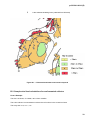


![NTT Web Hosting Service [User Manual]](http://vs1.manualzilla.com/store/data/005951289_1-c9e52ec4d0c5755656361886eb8624e9-150x150.png)