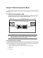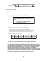
1
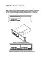
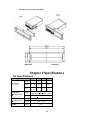
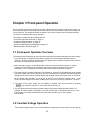
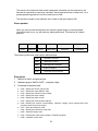
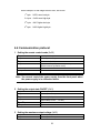
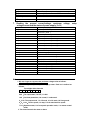
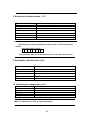
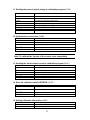
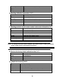
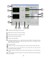
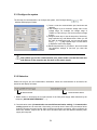
Instruction Manual Version: September 2, 2009 1 Programmable DC Power Supplies Model 1785B, 1786B, 1787B & 1788 Content Content ..................................................................................................................................................... 2 Quick Reference ............................................................................................................................................. 3 About your safety.................................................................................................................................... 3 General information........................................................................................................................ 3 Protection from electric shock ...................................................................................................... 3 Definition of users ........................................................................................................................... 3 Certification and Warranty..................................................................................................................... 4 Certification...................................................................................................................................... 4 Introduction .............................................................................................................................................. 4 The Front Panel at a Glance................................................................................................................. 5 Function keys description...................................................................................................................... 5 Menu description .................................................................................................................................... 6 Display annunciators.............................................................................................................................. 6 The Rear Panel at a Glance ................................................................................................................. 7 Chapter 1 Quick Start .................................................................................................................................... 8 1.1 Preliminary Checkout ...................................................................................................................... 8 1.2 Output Checkout .............................................................................................................................. 9 1.2.1 Voltage Output Checkout .................................................................................................... 9 1.2.2 Current Output Checkout .................................................................................................... 9 1.3 If the Power Supply Does Not Turn On ...................................................................................... 10 1.4 To Adjust the Carrying Handle ..................................................................................................... 10 1.5 To Rack Mount the Instrument ..................................................................................................... 11 Chapter 2 Specifications.............................................................................................................................. 12 2.1 Specifications ................................................................................................................................. 12 2.2 Supplemental Characteristics ...................................................................................................... 13 Chapter 3 Front-panel Operation ............................................................................................................... 15 3.1 Front-panel Operation Overview ................................................................................................. 15 3.2 Constant Voltage Operation ......................................................................................................... 15 3.3 Constant Current Operation ......................................................................................................... 16 3.4 Saving and Recalling Operation .................................................................................................. 16 3.5 Menu Operation ............................................................................................................................. 16 Chapter 4 Remote Operation Mode .......................................................................................................... 19 4.1 IT-E131 Communication cable..................................................................................................... 19 4.2 Communication setting ................................................................................................................. 19 4.3 Frame format .................................................................................................................................. 20 Packet structure ............................................................................................................................ 20 Status packets ............................................................................................................................... 21 4.4 Communication protocol ............................................................................................................... 23 Chapter 5 PV1785B-1788 Software .......................................................................................................... 29 5.1 Introduction ..................................................................................................................................... 29 5.2 System Installation......................................................................................................................... 29 5.3 Functions of PV-1785B-1788 ....................................................................................................... 29 5.3.1Configure the system .......................................................................................................... 31 5.3.2 Status bar ............................................................................................................................. 31 5.3.3 Setting Voltage and current............................................................................................... 32 5.3.4. GO/NG Test Function........................................................................................................ 34 5.3.5 Save and Open ................................................................................................................... 34 5.3.6 Present Voltage/Current Chart ......................................................................................... 34 5.3.7 Chart Description ................................................................................................................ 35 2 Quick Reference About your safety Pease review the following safety precautions before operating our equipment. General information The following safety precautions should be observed before using this product and any associated instrumentations. Although some instruments and accessories would be used with non-hazardous voltages, there are situations where hazardous conditions may be present. This product is intended for use by qualified personnel who recognize shock hazards and are familiar with the safety precautions required to avoid possible injury. Read and follow all installation, operation, and maintenance information carefully before using the product. Refer to this manual for complete product specifications. If the product is used in a manner not specified, the protection provided by the product may be impaired. Before performing any maintenance, disconnect the line cord and all test cables. Protection from electric shock Operators of this instrument must be protected from electric shock at all times. The responsible body must ensure that operators are prevented access and/or insulated from every connection point. In some cases, connections must be exposed to potential human contact. Product operators in these circumstances must be trained to protect themselves from the risk of electric shock. If the circuit is capable of operating at or above 1000 volts, no conductive part of the circuit may be exposed. Definition of users Responsible body is the individual or group responsible for the use and maintenance of equipment is operated within its specifications and operating limits, and for ensuring that operators are adequately trained. Operators use the product for its intended function. They must be trained in electrical safety procedures and proper use of the instrument. They must be protected from electric shock and contact with hazardous live circuits. Service is only to be performed by qualified service personnel. Safety symbols and terms Connect it to safety earth ground using the wire recommended in the user manual. The symbol on an instrument indicates that the user should refer to the operating instructions located in the manual. High voltage danger 3 Certification and Warranty Certification We certify that this product met its published specifications at time of shipment from the factory. Introduction The 1785B - 1788 Series power supplies are high performance single-output programmable DC power supplies with communication interface. The combination of bench-top and system features in these power supplies provides versatile solutions for your design and test requirements. Convenient bench-top features: • Nice appearance, small-size and light weight • VFD display • Soft Rubber numeric keypad • Adjustable & constant voltage outputs • Adjustable & constant current outputs • Output on/off • High accuracy and high resolution • Excellent load and line regulation • Low ripple and noise • Limit voltage protection • Over current/temperature protection • Sixteen operating states storage • May be used in series or parallel modes with additional power supplies 4 The Front Panel at a Glance ① ② ③ ④ ⑤ ⑥ ⑦ 10 digits VFD display Status information for operating mode and working status Power switch Number keys Function keys UP/DOWN and ENTER key Output terminals Function keys description V-set I-set Save Recall Menu Out on/off Set the output voltage value Set the current value Save the present settings to a specified register location(1~16) Recall a saved settings from location ‘‘1’’through ‘‘16’ Menu function to set related parameters of the power supply Output ON/OFF, to enable/disable the output 5 Menu description Menu >MAX VOLT >INIT OUT >INIT VOL >KEY SOUN >BAUD RATE >ADDR >KEY LOCK >EXIT Set the maximum output voltage value Initiate the output state to ON or not Initiate the output voltage to 0 volt or not Switch On/Off the buzzer sound when you press any key Set the communication baud rate Set the communication address Set the password for function keys Exit Display annunciators OFF * The power supply’s Timer output is off Constant voltage Sense mode Constant current Ext mode Adrs Not used Meter Meter mode Shift OVP Error Not used Over voltage protect Prot state Over current protect Lock state CV CC OCP Rmt 6 Not used Not used Not used The instrument is communicating with an IT-E131/IT-E132/IT-E133 The instrument is in remote state. The only active key is the Local KEY. The instrument has error Not used The keyboard is locked by a password The Rear Panel at a Glance 1 ① ② ③ ④ ⑤ 2 3 Cooling window DB9 interface connector 110V/220V selector Fuse Power socket 7 4 5 Chapter 1 Quick Start One of the first things you will want to do with your power supply is to become acquainted with the front panel. The exercises in this chapter prepare the power supply for use and help you get familiar with some of its front-panel operations. This chapter is intended for both the experienced and the inexperienced user because it calls attention to certain checks that should be made prior to operation. 1.1 Preliminary Checkout The following steps help you verify that the power supply is ready for use. 1.Check the list of supplied items. Verify that you have received the following items with your power supply. If anything is missing, contact your nearest Sales Office. □ One power cord for your location □ This User’s Manual. □ Communication cable 2.Connect the power cord and turn on the power supply. When you turn on the power supply, the front-panel display will light up briefly while the power supply performs its power-on self-test. All the VFD annunciators will light up at once. To review the display with all annunciators, you can check if there is any stroke loss on any annunciator. If there isn’t any response when you power on the power supply, please see Section 1.5 on page 10 for some service information. If the EEPROM was damaged or the latest operation data in EEPROM was lost, the VFD will display as follows: ERR EEPROM If the calibration data in EEPROM was lost, the VFD will display as follows: ERROR CAL Warning: Your power supply is equipped with a 3-wire grounding type power cord; the third conductor being the ground. The power supply is grounded only when the power-line cord is plugged into an appropriate receptacle. Do not operate your power supply without adequate cabinet ground connection. 8 1.2 Output Checkout The following procedures check to ensure that the power supply develops its rated outputs and properly responds to operation from the front panel. 1.2.1 Voltage Output Checkout The following steps verify basic voltage functions without load. 1. Turn on the power supply. 2. Enable the outputs. Press Out on/off key to let the ON annunciator and the CV annunciator turn on to light. Notice: if the voltage value flash, then the power supply is in Set mode, ‘‘Set mode’’ means that the VFD display shows the setting output voltage and current. Or the power supply is in Meter mode, ‘Meter mode” means that the VFD display shows the actual output voltage and current and the ”Meter” annunciator is lit. 3. Check that the front-panel voltmeter properly responds to number keys Set some different voltage values, then wait till the Meter mode to check if the VFD displayed voltage value is the same as the set voltage value, and to check if the VFD displayed current value is nearly zero. 4. Ensure that the voltage can be adjusted from zero to the full rated value. 1.2.2 Current Output Checkout The following steps check basic current functions with a short across the power supply’s output. 1. Turn on the power supply. 2. Disable the output Press Out on/off key to ensure that the output is disabled. The OFF annunciator is turned on. 3. Connect a short across (+) and (-) output terminals with an insulated test lead. Use a wire size sufficient to handle the maximum current. Warning:To satisfy safety requirements, load wires must be heavy enough not to overheat when carrying the maximum short-circuit output current of the power supply. If there is more than one load, then any pair of load wires must be capable of safety carrying the full-rated current of the power supply. 4. Enable the output. Press Out on/off key to ensure that the output is enabled. The OFF annunciator is turned off. 5. Adjust the voltage value to 1.0 volt. Adjust the voltage to 1.0 volt to ensure the power supply is in CC operation mode. The CC annunciator will turn on. 6. Adjust the current value. Set some different voltage values, then wait till the Meter mode to check if the VFD displayed current value is the same as the set voltage value, and to check if the VFD displayed voltage value is nearly zero. 7. Ensure that the current can be adjusted from zero to the full rated value. 8. Turn off the power supply and remove the short wire from the output terminals. 9 1.3 If the Power Supply Does Not Turn On Use the following steps to help solve problems you might encounter when turning on the instrument. If you need more help, refer to chapter 6 for instructions on returning the instrument to the supplier for service. 1. Verify that there is AC power to the power supply. First, verify that the power cord is firmly plugged into the power receptacle on the rear panel of the power supply. You should also make sure that the power source you plugged the power supply into is energized. Then, verify that the power supply is turned on. 2. Verify the power-line voltage setting. The line voltage is set to the proper value for your country (110VAC or 220VAC). Change the voltage setting if it’s not correct. 3. Verify that the correct power-line fuse is installed. If the fuse was damaged, please see the table below to replace the fuse for your power supply. Model 1785B, 1786B, 1787B Fuse Description Fuse 2.5A T 250V for 220VAC 1788 Fuse 3.15A T 250V for 220VAC Fuse 5A T 250V for 110VAC Fuse 6.3A T 250V for 110VAC 1.4 To Adjust the Carrying Handle To adjust the position, grasp the handle by the sides and pull outward. Then, rotate the handle to the desired position. Bench-top viewing positions Carrying position 10 1.5 To Rack Mount the Instrument You can mount the power supply in a standard 19-inch rack cabinet using the IT-E151 rack mount kit. Note: Remove the carrying handle and the two plastic ears before rack-mounting the instrument. To remove the handle, grasp the handle by sides and pull outwards and rotate it to a special position to let the arrow on the handle and the arrow on the plastic ears be in opposite directions, then pull the handle outward. After removing the handle, you can use a screwdriver to remove the two plastic ears. To rack mount a single instrument, order rack mount kit IT-E151 Side view of rack mounting a single instrument To rack mount two instruments side-by-side, order rack mount kit IT-E151, you 11 needn’t to use the front cover panel. unit (mm) Dimension Chapter 2 Specifications 2.1 Specifications Parameter Output Ratings, ( 0 °C - 40 °C) Load Regulation, 1785B 1786B 1787B 1788 Voltage 0 ~18 V 0 ~32 V 0 ~72 V 0 ~32 V Current 0 ~5 A 0 ~3 A 0~1.5 V 0~6 A LVP 0 ~19 V 0 ~33 V 0 ~73 V 0 ~33 V Voltage ±(%of output+offset) Line Regulation, ±(%of output+offset) Programming Resolution (rated current < 3 A) <0.01% + 3 mV (rated current< 10 A) <0.02% + 5 mV Current <0.01% + 3 mA Voltage <0.01% + 3 mV Current <0.1% + 2 mA Voltage 10 mV 12 Current 10 mA 10 mV(<20 V) 100 mV(≥20 V) Voltage Readback Resolution Current 10 mA Programming Voltage <0.05% + 10 mV Accuracy, 12months, (@ 25 °C ± 5 °C) ±(%of output+offset) Current <0.2%+10 mA Readback Accuracy 12months, (25 °C ± 5 °C) ±(%of output+offset) Voltage <0.05%+15 mV(<20 V), <0.05%+120 mV(≥20 V) Current <0.1%+15 mA Voltage ≤0.5 mVrms/3 mVp-p Current 5 mArms Temperature Coefficient, (0 °C ~ 40 °C) ±(%of output+offset) Voltage <0.02%+5 mV Current <0.1%+5 mA Readback Yemperature, Coefficient, ±(%of output+offset) Voltage Ripple (20Hz ~20MHz) <0.02%+15 mV(<20 V), <0.02%+120 Current mV(≥20 V) <0.1%+15 mA 2.2 Supplemental Characteristics State Storage Memory Sixteen (16) user-configurable stored states Recommended Calibration Interval 1 year AC Input Ratings (selectable via switch on the rear panel) Option OP1: 220VAC ± 10%, 47 to 63 Hz Option OP2: 110 VAC ± 10%, 47 to 63 Hz Maximum input power 350VA Cooling Fan cooled 13 Operating Temperature 32 to 104 °F (0 to 40 °C) for full rated output Storage Temperature -68 to 158 °F (-20 to 70 °C) for storage environment. Environmental Conditions Designed for indoor use in an installation category II, pollution degree 2 environment. Designed to operate at maximum relative humidity of 95% and at altitudes of up to 2000 meters. Weight Type N.W G.W 1785B 12.3Lbs. 5.6Kg 14Lbs. 6.4Kg 1786B 14.8Lbs. 6.7Kg 16.5Lbs. 7.5Kg 1787B 14.8Lbs. 6.7Kg 16.5Lbs. 7.5Kg 1788 14.8Lbs. 6.7Kg 16.5Lbs. 7.5Kg Dimensions WxHxD* 10” x 4.16” x 15” (255.7mm x 105.7mm x 382.7mm) (Unit: mm) 14 Chapter 3 Front-panel Operation So far you have learned how to install your power supply and do quick start. During the quick start, you were briefly introduced to operating from the front panel as you learned how to check basic voltage and current functions. This chapter describes in detail the use of the front-panel keys and shows how they are used to accomplish power supply operation. This chapter is divided into the following sections: • Front-Panel Operation Overview‚ on page 14 • Constant Voltage Operation‚ on page 15 • Constant Current Operation‚ on page 15 • Storing and Recalling Operating States‚ on page 15 • MENU operation, starting on page 16 3.1 Front-panel Operation Overview The following section describes an overview of the front-panel keys before operating your power supply. 1. The power supply is shipped from the factory configured in the front-panel operation mode. At power-on, the power supply is automatically set to operate in the front-panel operation mode. When in this mode, the front panel keys can be used. 2. When the power supply is in remote operation mode, you cannot use the front-panel. A change between front-panel and remote operation modes will not result in any change in the output parameters. You can change the front-panel and remote operation modes by computer. 3. The power supply is in Meter mode when it is powered on, and the VFD will display the actual voltage and current output value. And in this mode, if any non-functional key is pressed, the power supply will changed to Set mode, and the VFD will display the adjusted voltage and current value. In Set mode, the set voltage value will flash, you can press ▲ and ▼ keys to adjust the voltage value. In Set mode, the power supply will turn back to Meter mode if there is no any key is pressed for 3 seconds. 4. The output of the power supply can be enabled or disabled from the front panel by pressing Out on/off key. When the output is on, the ON annunciator will turn off. 5. The VFD display shows the present operating status of the power supply with annunciators. For example, the power supply is operating in CV mode, and then the CV annunciator will turn on. If, the power supply is remotely controlled, the Rmt annunciator will also turn on, See ‘‘Display Annunciators’’. 3.2 Constant Voltage Operation The constant voltage range is from 0V to the maximum voltage value of each model. It is very easy for 15 you to set the constant voltage output. You have 2 solutions to set the constant voltage value. Solution 1: Step1. Power on the Power Supply Step2. Press the ▲ and ▼ keys to change the value Solution 2: Step1. Power on the instrument Step2. Press V-Set key. 0 Step3. Use the numeric keys Step4. Press Enter 9 to or ▲ and ▼ keys to change the voltage value. to confirm the value 3.3 Constant Current Operation The constant current output range is from 0A to the maximum current value of each type. It is very easy for you to set the constant current output. Step1. Power on the Power Supply Step2. Press I-Set key 0 to Step3. Use the numeric keys Step4. Press Enter 9 or use ▲and ▼keys to change the current value key to confirm the value 3.4 Saving and Recalling Operation You can store up to 16 different output states in storage register locations (1 to 16). Each output state includes Constant voltage value, Constant current value and Maximum output voltage value. When shipped from factory, storage locations “1” through “16” are empty. You can recall the saved settings by Recall function. Step1. After you setting an output state (CV value, CC value and Maximum voltage), press Step2.Use the numeric keys Save key. 9 or ▲ and ▼ keys to select the memory location (the range 0 to is 1 to 16) which you want to store in. Step3. Press Enter to confirm the memory location. Step4. Press Recall key. Step5. Use numeric keys 0 to 9 or ▲ and ▼ keys to select the states which you want to recall. Step6. Press Enter key to confirm. Then the saved settings will come on. Note: 1. If the function keys were locked by password, you need to enter the correct password after you press function keys (V-set, I-set, Save, Recall and Menu), then you can do the settings. 2. If you want to cancel a function operation (V-set, I-set, Save, Recall or Menu), just press Esc key to exit. 3.5 Menu Operation 16 Set Maximum voltage(>MAX VOLT) Please be well known that the Max voltage value should be in the range of each type of Power supply. Step1. Press Menu key. Step2. Select >MAX VOLT by using▲ and ▼ key. Step3. Press Enter key. Step4. Change the voltage value by using numeric keys Step5. Press Enter 0 to 9 or ▲and ▼key. key. Note: After you setting the maximum voltage value, the output voltage setup should be in the range from 0 volt to maximum voltage. The default maximum voltage is the full voltage range of its model. Initiating the Output state(>INIT OUT) This instruction can initiate the output state when the power supply is powered on. If you select ON, the power supply will initiate the output to OFF state when the power supply is powered on. If you select OFF, the output will remain the same state as last time you turned off the power supply Note: Default selection is ON and the output state is always OFF state. Initiating the Output Voltage (>INIT VOLT) This instruction can set the initial output voltage. If you select ON, the power supply will initiate the output voltage to 0Volt when the power supply is powered on. If you select OFF, the output voltage will remain as the same volts as the last time you turned off the power supply Note: Default setting is ON and the output voltage is 0 volt. Setting the Key Sound(>KEY SOUND) This instruction can switch on/off the buzzing sound when you press any key, If you select ON, the buzzer will sound when any key was pressed. If you select OFF, the buzzer will not sound when the keys were pressed. Note: Default setting is ON; the buzzer will sound when you press any key. Setting the Baud Rate(>BAUDRATE) This instruction can change the communication baud rate for the power supply, 17 the baud rate range is 4800,9600,19200 or 38400。Before the communication, you must make sure that there is same baud rate between the power supply and the computer. Note: Default baud rate is 4800. Setting Address (>ADDRESS) This instruction can set the communication address for each power supply. The address range is from 0 to 30. Before the communication, you must make sure that there is same address between the power supply and the computer. Note: Default address is 0. When the power supply receives a frame instruction from computer, the LINK indicator will light on; it means that the power supply started to communicate with computer. If the power supply hasn’t received the signal from computer for 3 seconds, the LINK indicator will be turned off and it means that the power supply can not communicate with computer. Setting password for function keys(>KEY LOCK) This instruction can set a password (1 through 4 digits) to lock the function keys operation. After setting the password, all the function keys on the front panel will be locked except the OUT on/off key. You must enter the correct password to unlock them, then you can continue to do the function key operation. If you don’t want to lock the function keys, please don’t press any number key when you enter the >KEY LOCK instruction, just press ENTER key to unlock it. Note: When shipped from factory, there is no password and function keys are unlocked. The start bit of your desired password shouldn’t be 0. 18 Chapter 4 Remote Operation Mode The DB9 interface connector on the rear panel of the power supply can be transferred to RS-232 interface, the following information will tell you how to use the computer to control the output of the power supply. 4.1 IT-E131 Communication cable The DB9 interface connector on the rear panel of power supply is TTL voltage level; you can use the communication cable (IT-E131) to connect the DB9 interface connector of the power supply and the RS-232 interface connector of computer for the communication. Computer side TTL→RS232 Cable (IT-E131) PS side IT-E131 communication cable Power Load supply COMPUTER IT RS232 IT-E131 ISOLATED COMMUNICATION CABLE ISOLATION RX TTL(5V) TX 859666668889942311 INSTRUMENT PC PC Note: It will not work if you connect the DB9 interface connector of the power supply to the RS232 interface connector of computer directly by a standard RS232 cable. Please use IT-E131 to connect them. 4.2 Communication setting Before using the remote operation mode, please make sure that the baud rate and communication address in power supply are the same as in the computer software, otherwise, the communication will fail, you can change the baud rate and communication address from the front panel or from computer. 1. Address: the range is from 0 to 254,default setting is 0 2. Baud rate: 4800,9600,19200 and 38400 are selectable, default setting is 4800 3. Data bit:8 bit 4. Stop bit:1 5. Parity:None 19 PARITY = NONE Start Bit 8 Data Bits Stop Bit 4.3 Frame format Packet structure The power supply is programmed using packets of bytes. A packet always contains 26 bytes, either going to or coming from the instrument. The basic programming rule is: You send a 26 byte packet to the instrument. You then read a 26 byte packet back from the power supply to either • Get the status of your submitted packet, or • Get the data you requested. The following are conventions we will follow in this chapter: 1. Hexadecimal integers will be represented by the prefix 0x. 2. Numbers are in base 10 number system unless otherwise indicated. 3. Byte numbering is zero-based, meaning numbering starts with 0. The structure of each 26 byte packet is: Byte 0 Byte 1 Byte 2 Byte 3 to 24 Byte 25 0xAA Address Command Command's data Checksum Thus, the first byte of any command packet or returned packet is always 0xAA. Address must be a byte that is between 0x00 and 0xFE. Setting of the address is optional. It is not required to communicate with the instrument. The address can be set from the front panel and is stored in non-volatile memory. This feature is useful when communicating via USB, and connecting several instruments, e.g. via a USB hub. In this scenario, Windows assigns a virtual COM port to each device which is unknown prior to establishing communications with the instrument (could be different each time). In this case, the user can correlate each virtual COM port randomly assigned by Windows with a user defined address. Command is a byte that identifies which power supply command is used. 20 The area for the command's data contains parameter information for the command or the data that is requested via a previous command. Some commands have no data at all. It is a good programming practice to set all unused bytes to 0x00. The checksum number is the arithmetic sum of each of the bytes modulo 256. Status packets When you send a command that does not cause the power supply to send requested information back to you, you will receive a status packet back. The structure of a status packet is Byte 0 Byte 1 Byte 2 Byte 3 Byte 4 to 24 Byte 25 0xAA Address 0x12 Status byte Reserved Checksum The meaning of the return status byte is defined below: 0x90 Checksum incorrect 0xA0 Parameter incorrect 0xB0 Unrecognized command 0xC0 Invalid command 0x80 Command was successful Description: 1. Start bit is 0xAA, occupies a byte. 2. Address range is 0x00 to 0xFE,occupies a byte. 3. Command occupies a byte. a. 0x20----Setting the remote control mode b. 0x21----Setting the output ON/OFF state c. 0x22----Setting the maximum output voltage d. 0x23----Setting the output voltage e. 0x24----Setting the output current f. 0x25----Setting the communication address g. 0x26----Reading the present current/voltage, maximum voltage, setup voltage/current and operation states of the power supply. h. 0x27----Enter the calibration mode i. 0x28----Reading the calibration mode state j. 0x29----Calibrate voltage value. k. 0x2A----Sending the actual output voltage to calibration program. l. 0x2B----Calibrate current value. 21 m. 0x2C----Sending the actual output current to calibration program. n. 0x2D----Save the calibration data to EEPROM. o. 0x2E----Setting calibration information. p. 0x2F----Reading calibration information. q. 0x31----Reading product’s model, series number and version information. r. 0x32----Restoring the factory default calibration data. s. 0x37----Enable the local key. t. 0x12----The return information of command operation in power supply. Note: You must change the power supply to remote control mode first, then you can control the power supply output by computer. The command for remote control is 0x20. If you want to calibrate the power supply, set the calibration information. If you want to set the product serial number, you must set the calibration protection mode to OFF state first. The command for calibration protection is 0x27. When the power supply is in calibration mode, changes for the output state of power supply are not allowed. 4. 4th to 25th bytes are information content 5. 26th byte is check sum, the sum of the former 25 bytes. Command Details: In the following sections, we abbreviate the details of the commands. Since the first three bytes of a command are i) the constant 0xAA, ii) the instrument address, and iii) the command, we will not show those for each command. In addition, the 26th byte, the checksum, will also not be shown. The table includes a column for Byte offset. This is the zero-based index of the byte in the packet. Note the offset numbers are in decimal. A table entry of “Reserved” means the data are currently unused or reserved for future use. Good programming practice is to set these bytes to 0x00. Some commands require two byte and four byte integers to represent parameter settings. These integers are stored in the command packet in little-endian format. Little-endian is a byte ordering format in which bytes with lower addresses have lower significance. We will refer to the individual bytes as follows: For a two byte integer, the least significant byte will be called the low byte and the most significant byte will be called the high byte. For a four byte integer, we will use the following notation: Least significant two bytes, least significant byte Least significant two bytes, most significant byte Most significant two bytes, least significant byte Most significant two bytes, most significant byte 22 As an example, for the integer 0x23A749F5, we’d have 1st byte: 0xF5 Lower low byte 2nd byte: 0x49 Lower high byte 3rd byte: 0xA7 Higher low byte 4th byte: 0x23 Higher high byte 4.4 Communication protocol 1.Setting the remote control mode (0x20) st Start bit( 0xAA ) nd Address(0x00~0xFE) rd Command (0x20) Operation mode(0 represent front panel operation mode, 1 represent remote operation mode) System reserve Check sum 1 byte 2 byte 3 byte th 4 byte th th 5 to 25 byte th 26 byte Note: You cannot control the power supply from the front panel when the power supply is in calibration mode. 2.Setting the output state ON/OFF (0x21) st Start bit (0xAA ) nd Address(0x00~0xFE) rd Command (0x21) 1 byte 2 byte 3 byte th 4 byte th th 5 to 25 byte th 26 byte Output state(0 is OFF,1 is ON) System reserve Check sum 3.Setting the maximum output voltage (0x22) st 1 byte nd 2 byte Start bit (0xAA ) Address(0x00~0xFE) 23 rd Command (0x21) The lowest byte of voltage upper limit (1 represents 1 mV) The lower byte of voltage upper limit th The higher byte of voltage upper limit th The highest byte of voltage upper limit System reserve Check sum 3 byte th 4 byte th 5 byte 6 byte 7 byte th th 8 to 25 byte th 26 byte Note: Suppose you want to set the maximum voltage to 16.23 V. Since 1 represents 1mV, therefore 16.23 V translates to 16,230 in decimal. With 4 bytes in Hex, that would be 0x0003F66. Since the bytes are ordered in little-endian format, 0x66 would be the 3rd byte, 0x3F the 4th byte, 0x00 as 5th byte, and 0x00 as the 6th byte. 4. Setting the output voltage (0x23) st Start bit (0xAA ) nd Address(0x00~0xFE) 1 byte 2 byte rd 3 byte th 4 byte th 5 byte th 6 byte th 7 byte th th 8 to 25 byte th 26 byte Command(0x23) The byte 0 of output voltage value The byte 1 of output voltage value The higher byte of output voltage value The highest byte of output voltage value System reserve Check sum 5.Setting the output current (0x24) st Start bit (0xAA ) nd Address (0x00~0xFE) 1 byte 2 byte rd 3 byte Command(0x24) To set the low byte of current value th 4 byte th 5 byte th (1 represents 1 mA) To set the high byte of current value th 6 to 25 byte th 26 byte System reserve Check sum Note: Suppose you want to set the maximum current to 3.12 A. Since 1 represents 1 mA, 3.12 A translates to 3,120 in decimal. With 2 bytes in Hex, that would be 0x0C30. Since the bytes are ordered in little-endian format, 0x30 would be the 4th byte, and 0x0C as 5th byte. 6. Setting the communication address (0x25) 24 st 1 byte nd 2 byte rd 3 byte th 4 byte th th 5 to 25 byte th 26 byte 7. Start bit ( 0xAA ) The current address of power supply(0x00~0xFE) Command(0x25) The new address System reserve Check sum Reading the present current/voltage, maximum voltage/current and the states of power supply. (0x26) st 1 byte nd 2 byte rd 3 byte th 4 byte th 5 byte th 6 byte th 7 byte Start bit ( 0xAA) Address(0x00~0xFE) Command(0x26) Byte 0 of present output current value Byte 1 of present output current value Byte 0 of present output voltage value Byte 1 of present output voltage th Byte 2 of present output voltage th Byte 3 of present output voltage 8 byte 9 byte th Power supply’s state th To set the low byte of current value th To set the high byte of current value Byte 0 of the maximum voltage value Byte 1 of the maximum voltage value Byte 2 of the maximum voltage value Byte 3 of the maximum voltage value Byte 0 of output voltage value Byte 1 of output voltage value Byte 2 of output voltage value Byte 3 of output voltage value System reserve Check sum 10 byte 11 byte 12 byte th 13 byte th 14 byte th 15 byte th 16 byte th 17 byte th 18 byte th 19 byte th 20 byte st th 21 to 25 byte th 26 byte voltage, Note: 1. We use 4 bytes to represent the maximum voltage value as follows: Byte 3 Byte 2 Byte1 Byte0 2. We use 1 byte to represent power supply’s state. Each bit is defined as follows: From higher bit to lower bit 7 6 5 4 3 2 1 0 0 bit:The output state, 0 is OFF, 1 is ON. 1 bit:Over heat protection, 0 is normal, 1 is abnormal. 2、3 bit: The output mode, 1 is CV mode, 2 is CC mode,3 is Unreg mode. 4、5、6 bit:The fan speed, 0 is stop, 5 is the maximum fan speed. 7 bit:Operation state, 0 is front panel operation mode, 1 is remote control mode. 3. The frame format is the same as above 25 setup 8. Entering the calibration mode(0x27) st 1 byte nd 2 byte rd 3 byte th 4 byte th 5 byte Start bit(0xAA) Address(0x00~0xFE) Command(0x27) Calibration protection state Calibration password(0x28) th 6 byte th Calibration password(0x01) th 7 to 25 byte th 26 byte System reserve Check sum Note: We use a byte to represent calibration protection state,each bit is defined as follows: from higher bit to lower bit 7 6 5 4 3 2 1 0 0 bit:Protection state, 0 is to disable protection, 1 is to enable the protection. 9. Reading the calibration state (0x28) st Start bit(0xAA) nd Address(0x00~0xFE) rd Command(0x28) Calibration protection state System reserve Check sum 1 byte 2 byte 3 byte th 4 byte th 5 byte th 26 byte 10. Calibrating the voltage value (0x29) st 1 byte nd 2 byte rd 3 byte th 4 byte th th 5 to 25 byte th 26 byte Start bit(0xAA) Address(0x00~0xFE) Command(0x29) Calibrated voltage points(point 1-3) System reserve Check sum Note: To calibrate the 3 points of voltage sequentially. 26 11. Sending the present output voltage to calibration program (0x2A) st Start bit (0xAA) nd Address(0x00~0xFE) rd Command(0x2A) The byte 0 of present voltage value The byte 1 of present voltage value The byte 2 of present voltage value The byte 3 of present voltage value System reserve Check sum 1 byte 2 byte 3 byte th 4 byte th 5 byte th 6 byte th 7 byte th th 8 to 25 byte th 26 byte 12. Calibrate the current value (0x2B) st Start bit(0xAA) nd Address(0x00-0xFE) Command(0x2B) th Calibrated current points( point 1-2) System reserve Check sum 1 byte 2 byte rd 3 byte 4 byte th th 5 to 25 byte th 26 byte Note: To calibrate the 2 points of the current value sequentially. 13. Sending the actual output current to calibration program (0x2C) st 1 byte nd 2 byte rd 3 byte th 4 byte th 5 byte th th 6 to 25 byte th 26 byte Start bit (0xAA) Address(0x00~0xFE) Command(0x2C) The lower byte of the present current value The higher byte of the present current value System reserve Check sum 14. Save the calibration data to EEPROM(0x2D) st 1 byte nd 2 byte Start bit(0xAA) Address (0x00~0xFE) rd 3 byte th Command(0x2D) th 4 to 25 byte th 26 byte System reserve Check sum 15. Setting calibration information (0x2E) st 1 byte nd 2 byte rd 3 byte Start bit (0xAA) Address (0x00~0xFE) Command(0x2E) 27 th rd 4 to 23 byte th 24 byte th 25 byte th 26 byte Calibration information(ASIC code) System reserve System reserve Check sum 16. Reading calibration information (0x2F) st 1 byte nd 2 byte rd 3 byte th Start bit (0xAA) Address (0x00~0xFE) Command(0x2F) Calibration information(ASCII code) rd 4 to 23 byte th System reserve th System reserve th Check sum 24 byte 25 byte 26 byte 17. Reading product’s model, series number and version information (0x31) st Start bit (0xAA) nd Address (0x00~0xFE) 1 byte 2 byte rd 3 byte th Command(0x31) Product model(ASIC code) Lower byte of the software version Higher byte of the software version Serial number(ASCII code) System reserve th 4 to 8 byte th 9 byte th 10 byte th th 11 to 20 byte st th 21 to 25 byte th 26 byte Check sum Note: For example, the serial number is 000045,the product model is 1785B,and software version is V2.03, then the returned data is as follows: AA 00 31 36 38 31 31 00 03 02 ZZ ZZ ZZ ZZ ZZ ZZ ZZ ZZ ZZ ZZ 18. Restore the factory default calibration data (0x32) st 1 byte nd 2 byte Start bit (0xAA) Address(0x00~0xFE) rd 3 byte th Command(0x32) th 4 to 25 byte th 26 byte System reserve Check sum 19.Enable the local key (0x37) st Start bit ( 0xAA) Address (0x00-0xFE) rd Command (0x37) th Enable/disable local key (0 is disable, 1is enable) System reserve Check sum code 1 byte nd 2 byte 3 byte 4 byte th th 5 to 25 byte th 26 byte 28 XX XX XX XX XX 57 Note: The local keys on the front panel are not allowed to use when the power supply is in remote mode. If the local key was enabled, user can press the numeric key 7 to change the remote mode to front panel operation mode and all local keys will work. 20. The return information of command operation in power supply (0x12) st 1 byte nd 2 byte rd 3 byte th 4 byte th th 5 to 25 byte th 26 byte Start bit (0xAA) Address (0x00~0xFE) Command(0x12) Command checkout result System reserve Check sum Note: When the power supply receives a frame command, it will check the frame command, if the check sum is correct, then it will return to 0x80, if there is any error on setting parameter or over parameter, then it will return to 0xA0, if the command wasn’t executed, then it will return to 0xB0, if the command isn’t effective, then it will return to 0xC0. Or otherwise, it will return to 0x80. Chapter 5 PV1785B-1788 Software 5.1 Introduction Software PV1785B-1788 is control software for IT1785B-1788 series programmable power supply. It can work with all single-output power supply models. Please make sure that you purchased communication cable, and use it to connect the power supply and computer before the communicating. This software can accomplish all the functions of the power supply, such as setting constant voltage, setting constant current, max voltage etc. Also you can make quickly settings or make a program for the output voltage and current by the computer. In addition, PV1785B-1788 offer a GO/NG test function for automatic factory testing. It brings you much convenience when you use the power supply. 5.2 System Installation 1.Requirements for the computer Pentium III or Pentium IV processor-based personal computer Windows 98/2000/XP or Windows NT4.0 2. Insert the CD-Rom which supplied with the instrument to the CD driver, and install the software step by step according to the instructions. 5.3 Functions of PV-1785B-1788 Start the software PV1785B-1788, the windows is as follows: 29 1 11 2 10 9 3 4 5 1 6 7 8 Configure the software operation environments. 2 Voltage chart, it can show you a chart of the voltage. 3 Current chart: it can show you a chart of the current. 4 5 To set the remote mode of power supply. 6 To enable the local numeric key ⑦,it means that if you select “Enable” on this button, when the To set the output state ON/OFF power supply is under remote control mode, you can press numeric key ⑦ to change the control mode to front panel control mode. 7 Annunciators display. 8 Status bar, it can show you the power supply model, communication status and operation status. 9 To set current value, use the rotary knob to set the current value, the setup value and measurement value will be displayed. 10 To make a program of voltage and current values for the power supply, or to set the output value quickly. 11 Using the rotary knob to set the voltage value, the setup value and present value will be displayed in the 2 indicators. 30 5.3.1Configure the system The first step for communication is to configure the system, click Configure button windows will display as follows: , the 1) Comm: to set the communication port, baud rate and address. 2) Max voltage: to set a maximum voltage value in the voltage range. For example, the voltage range of IT6822 is 0~32V, then you can set a maximum voltage at 24V. 3) Voltage/Current step: to set the step size of Arrow key, page up/down key, and Mouse-wheel. When you set the value by clicking the knob, you can use the arrow keys (↑, ↓, ←, →), page up/down keys or mouse wheel to adjust the value more slightly. 4) Reload last parameter: if you select it, then it will reload the parameter settings of last time you close this software. Note:When you set the communication port, please make sure that the baud rate and address of the computer are the same as the power supply. 5.3.2 Status bar Status bar will give you the communication information. When the communication is successful, the status bar will display as follows: Model number Communication status 1. Model number: it will display the real part number of the field power supply which detected by the computer. (6811/6812/6821/6822/6823……..). 2. Communication status (Communication successful/Communication waiting), if Communication waiting appears here for more than 10 seconds, you need to check if there is any connection failure between computer and power supply. After confirming the effective connection, then re-configure the baud rate, address, comport etc, to make sure the same baud rate and address between power supply and computer. 31 5.3.3 Setting Voltage and current 1. Setting voltage/current by rotary knob Use mouse to click on the rotary knob and move mouse to change the value. You also can use mouse wheel, or Page Up/Down keys and arrow keys (↑, ↓, ←, →) from the keyboard to change the voltage value more slightly. The setup value will be displayed on the second line indicator. Use mouse to click on the rotary knob and move mouse to change the value. Also you can use mouse wheel, Page Up/Down keys and arrow keys (↑, ↓, ←, →) from the keyboard to change the current value more slightly. The setup value will be displayed on the second line indicator. Note: Before you set the current and voltage value from the computer, please change the operation mode to PC Control mode by pressing button. 2. Quickly setting Hot Key: Right-click each Hotkey Button, it will display as “Modify Voltage/Current”. Click “Modify/Voltage/ Current”, it will display as follows, change the voltage/current value as you desired, then click OK button to confirm. 32 Voltage Sweep: To set voltage sweep. For example, StartValue=1V, Stop Value=12V, Voltage Step=0.5V, TimeDelay=2s. When you click the “Run” button, the voltage will change according to the voltage sweep setup value, display as follows: then you can click “Stop” button to stop the voltage sweep. 3. Program setting Program: Right-click on the Program area, the program tools (AppendLine, Insert Line, DeleteLine) will appear on the window. Click the tools to program the steps. Double-click on each value to change them from key board as you desired. Also you can change the time unit (hour/minute/second) by clicking on “Sec”. After programming, you can select a run mode for your program. (Run mode includes Once, Repeat and Custom). Click “Run” button to send the program settings to the power supply. The power supply’s output will respond to the program. Click “Stop” button to stop sending the program settings to the power supply. The power supply state will return to the state before the program running. 33 5.3.4. GO/NG Test Function GO/NG is an auto test function, to test if the EUT (equipment under test) can meet the specification. To use this function, follow up the steps below: 1. Right-click on the window, the edit tools (Append a line, Insert a line, Delete a line, Delete Select etc.) will appear on the window. Use the edit tools to edit the test steps. 2. To set the Voltage, Max Amps, Min Amps and Delay time according to the specifications of the EUT. 3. Click the Run button to start the test. If the Real Amps of all steps are in the range of Min Amps to Max Amps, then the EUT will pass the test, the Pass window will appear. 4. If there is a Real Amps beyond the range in any step, the EUT will not pass the test. 5.3.5 Save and Open To save the program settings, quickly settings, voltage sweep settings and GO/NG settings as PAR file. To open the PAR file for reloading the program settings, quickly settings, voltage sweep settings and GO/NG settings. 5.3.6 Present Voltage/Current Chart Double click the voltage chart, the voltage chart will be enlarged and will display as more details. Double click the current chart, the current chart will be enlarged and will display with more details. 34 5.3.7 Chart Description The voltage and current chart can help you to analyze voltage and current changes more easily. We take the voltage chart as the example to let you know how to use it. The chart window is as follows: Click here and move to zoom in/out axes or scroll axes To set the Y-Axes Span To set the X-Axes Span Vertical marker Horizontal marker XY Value marker Limit range between the minimum value and maximum value. Scroll axes mode Zoom in/out axes mode Zoom out Zoom in Save the chart as a .BMP file. Clear all data Resume tracking Auto scale Print the chart Zoom rectangle 35 SERVICE INFORMATION Warranty Service: Please go the support and service section on our website www.bkprecision.com to obtain a RMA #. Return the product in the original packaging with proof of purchase to the address below. Clearly state on the RMA the performance problem and return any leads, probes, connectors and accessories that you are using with the device. Non-Warranty Service: Please go the support and service section on our website www.bkprecision.com to obtain a RMA #. Return the product in the original packaging to the address below. Clearly state on the RMA the performance problem and return any leads, probes, connectors and accessories that you are using with the device. Customers not on an open account must include payment in the form of a money order or credit card. For the most current repair charges please refer to the service and support section on our website. Return all merchandise to B&K Precision Corp. with pre-paid shipping. The flat-rate repair charge for Non-Warranty Service does not include return shipping. Return shipping to locations in North America is included for Warranty Service. For overnight shipments and non-North American shipping fees please contact B&K Precision Corp. B&K Precision Corp. 22820 Savi Ranch Parkway Yorba Linda, CA 92887 www.bkprecision.com 714-921-9095 Include with the returned instrument your complete return shipping address, contact name, phone number and description of problem. LIMITED ONE-YEAR WARRANTY B&K Precision Corp. warrants to the original purchaser that its products and the component parts thereof, will be free from defects in workmanship and materials for a period of one year from date of purchase. B&K Precision Corp. will, without charge, repair or replace, at its option, defective product or component parts. Returned product must be accompanied by proof of the purchase date in the form of a sales receipt. To obtain warranty coverage in the U.S.A., this product must be registered by completing a warranty registration form on our website www.bkprecision.com within fifteen (15) days of purchase. Exclusions: This warranty does not apply in the event of misuse or abuse of the product or as a result of unauthorized alterations or repairs. The warranty is void if the serial number is altered, defaced or removed. B&K Precision Corp. shall not be liable for any consequential damages, including without limitation damages resulting from loss of use. Some states do not allow limitations of incidental or consequential damages. So the above limitation or exclusion may not apply to you. This warranty gives you specific rights and you may have other rights, which vary from state-to-state. B&K Precision Corp. 22820 Savi Ranch Parkway Yorba Linda, CA 92887 www.bkprecision.com 714-921-9095 36 22820 Savi Ranch Parkway Yorba Linda, CA 92887 www.bkprecision.com © 2008 B&K Precision Corp. Printed in China v090209 37