1
TM/TMC/RM/RMC-1402CL
Note:
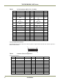
Pin #
Description
I/O
Pin #
Description
I/O
12
N/C
In
25
N/C
In
13
GND
26
GND
SerTC: Differential Serial Communication to camera; SerToFG: Differential Serial Communication to
frame grabber.
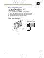
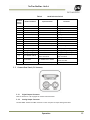
2.2.2 (e) Analog Output Connector
The TM-1402 has a BNC connector on the rear panel
to output non-standard analog video.
2.2.3
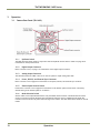
Shutter Speed Control Dial (TM-1402 only)
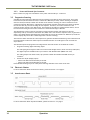
8
7
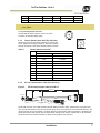
Shutter speed can be selected by switching the shutter dial
to the appropriate setting (0 through 9). The factory default
settings correspond to the shutter speeds as shown in below.
Table 5
9 0 1
2
3
6 5 4
Shutter Speed Control Dial
Shutter Exposure Time (Seconds)
Normal
Async
no shutter (1/30)
no shutter (1/30)
1
1/60
1/16,000
2
1/125
1/8,000
3
1/250
1/4,000
4
1/500
1/2,000
5
1/1,000
1/1,000
6
1/2,000
1/500
7
1/4,000
1/250
8
1/8,000
1/125
9
1/16,000
Ext. pulse width control
0
2.2.4
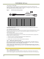
RS-232 Communication Cable (TM-1402 only)
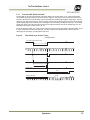
Figure 5.
Serial Communication Cable RS-232B-12
2000±20mm
40±3mm
1925±10mm
Receptacle
75mm±5mm
1
6
5
9
Jack
190±5mm
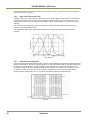
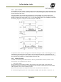
The RS-232 controller set CS-232E includes cable RS-232B-12 interface cable, software disk, and a quick-start
card. The TM-1402 camera’s built-in look-up table (LUT) can be controlled by an external RS-232 interface. The
camera settings can be programmed or changed using the communication cable and software. Commands from
the RS-232 interface will override the rear panel switch settings of the camera. Please refer to the AccuPiXEL
Series Camera-Control Software manual for details on the graphical user interface.
Installation
7