1
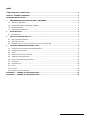
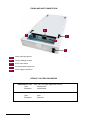
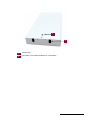
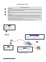
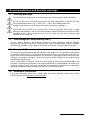
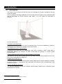
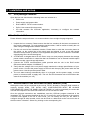
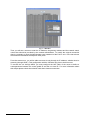
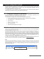
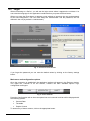
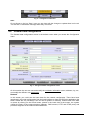
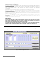
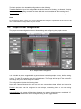
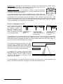
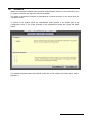
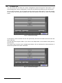
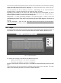
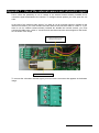
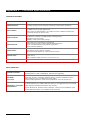
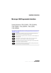
PECO1 ENGLISH User Manual INDEX FIXING AND UNIT CONNECTION ....................................................................................................................2 DEFAULT ACCESS PASSWORD .....................................................................................................................2 NETWORK INSTALLATION ..............................................................................................................................4 1 2 RECOMMENDATIONS AND SECURITY WARNINGS ............................................................................5 1.1 SECURITY WARNINGS ...............................................................................................................................5 1.2 ELECTROMAGNETIC COMPATIBILITY (EMC) ...............................................................................................5 1.3 RESPONSIBILITIES ....................................................................................................................................5 1.4 ADDITIONAL INFORMATION ........................................................................................................................5 INTRODUCTION........................................................................................................................................6 2.1 3 4 DESCRIPTION ...........................................................................................................................................6 INSTALLATION AND SET-UP ..................................................................................................................7 3.1 UNIT PACKAGE CONTENTS ........................................................................................................................7 3.2 UNIT INSTALLATION ..................................................................................................................................7 3.3 REMOTE START OF THE UNIT FROM THE LOCAL NETWORK (LAN) .................................................................7 COUNTER CONFIGURATION AND TEST ...............................................................................................9 4.1 CONFIGURATION WORKSTATION REQUIREMENTS ........................................................................................9 4.2 CONNECTION PROCESS ............................................................................................................................9 4.3 LOGIN....................................................................................................................................................10 4.4 GENERAL DATA CONFIGURATION ............................................................................................................11 4.5 TIMETABLE CONFIGURATION ...................................................................................................................12 4.6 PEOPLE COUNTER CONFIGURATION .........................................................................................................13 4.7 ADVANCED ............................................................................................................................................15 4.8 COUNTER TEST ......................................................................................................................................16 4.9 LOGS.....................................................................................................................................................17 4.10 LOGOUT ................................................................................................................................................18 4.11 PECO1 FACTORY SETTINGS ...................................................................................................................18 APPENDIX 1 – TECHNICAL SPECIFICATIONS ............................................................................................19 APPENDIX 2 – TECHNICAL SPECIFICATIONS ............................................................................................20 User Manual - 1 FIXING AND UNIT CONNECTION 3 5 1 2 4 1 Ceiling mounting groove 2 “Factory settings” button 3 TCP/IP connection 4 Count and power supply led 5 Power supply connection DEFAULT ACCESS PASSWORD Administrator user – Web and PecoGraph application access: User: administrator Password: administrator Peco user – only from PeCoGraph application: User Manual - 2 User: peco Password: pecouser 1 2 1 Camera lens 2 Connection of an external camera or a volumetric User Manual - 3 NETWORK INSTALLATION Quick installation guide PeCo1 unit Use the VSFinder (contained in the CD) to configure the internal IP address, the gateway and the subnet mask. Consult the network administrator Router Open the TCP port 80 and map the internal IP address of the unit to the external one of the router. Operator PC To connect to the unit from the operator PC use the router external IP address or the name ‘identity.dnsvideo.net’*, identity being the serial number of the unit (SN followed by 14 digits). * Accessing the unit through its identity is needed when using dynamic IP address, and it requires enabling the dynamic IP service (advanced configuration). For further information, please consult the technical note about Internet connection. PeCo1 Local IP: 192.168.1.100 Gateway: 192.168.1.1 Mask: 255.255.255.0 PC Explorer / PeCoGraph Remote node Connection PeCo1 2.2.2.1 / identity.dnsvideo.net Router Local IP: 192.168.1.1 External IP: 2.2.2.1 Table NAT Local IP External IP 192.168.1.100:80 2.2.2.1:80 Internet connection example User Manual - 4 1 Recommendations and Security warnings 1.1 Security warnings The electric power socket must be located close to the unit and must be easily reachable. Do not use the unit in an extreme environment with high temperatures or humidity. Use the unit at temperatures within +5ºC - +40ºC (41ºF – 104ºF) and humidity below 90%. Handle the unit with care. Do not strike it or shake it, as this may damage it. Protect the unit from water or dust. Do not use it in wet environments. Prevent the unit from droppings and spattering, and do not locate recipients containing liquids, like glasses. Do take immediate action if the unit becomes wet. Turn the power off and refer servicing to the qualified service personnel. 1.2 Electromagnetic compatibility (EMC) The CE mark is affixed to the enclosed product to confirm compliance with the following European Community Directives for a Class B digital device: EN55022/1994, related to radiated emission and EN50082-1/1997 related to residential, commercial, and light industry immunity. 1.3 Responsibilities This manual has been prepared with the maximum care. However, if you detect any inaccuracies or omissions, please inform us at the address that can be found in the warranty of this manual. Visual Tools cannot be held responsible for any technical or typographical errors and due we are improving our products constantly, reserves the right to make changes to the product and/or manuals without prior notice. Visual Tools makes no warranty of any kind with regard to the material contained within this document, including, but not limited to, the implied warranties of merchantability and fitness for a particular purpose. Visual Tools shall not be liable or responsible for incidental or consequential damages in connection with furnishing, performance or use of this material. 1.4 Additional information For further information about PeCo, please check the on-line technical notes located on the Visual Tools web site: http://www.visual-tools.com. HTU U User Manual - 5 2 Introduction 2.1 Description The PeCo1 is an IP people counter and client flow estimator for all types of premises that are open to the public. The unit analyzes the images obtained from its internal camera and gets counting statistical data that it’s transmitted via TCP/IP (Internet, LAN, WAN….) to a PC where the information is analyzed. Its main features are: SCALABLE AND MODULAR It permits the grouping of as many units as necessary and in successive installations. Thanks to the flexibility of its architecture, it adapts to the client’s needs. HIGH PERCENTAGE OF ACCURANCY It measures the visitor flow in a determined area with a reliability of 95%1, being able to differentiate between the direction of traffic (in/out) and the passage of several people simultaneously. CONFIGURATION AND ACCESS VIA MS INTERNET EXPLORER UPnP device. From any PC or laptop, the user can easily access the Web interface of the unit to carry out its configuration and diagnosis. OPERATION FROM ANY PC For the functional and commercial use of the counting data the PeCo-Graph software is supplied. It permits manual or programmed data downloads from different units simultaneously, their analysis and export. USE OF EXTERNAL DEVICES You have the possibility of using an external camera already installed and a volumetric signal associated to the counter. 1 95% reliability in measurements of more than 100 records User Manual - 6 3 Installation and set-up 3.1 Unit package contents Open the box and check that the following items are included in it: 3.2 PeCo1 unit Power supply and power cable RJ45 cable for TCP/IP communication. PeCo1 User manual (this document) CD that contains the VSFinder application, necessary to configure the network information. Unit installation Please follow the steps set below. It is recommended to have at sight the page diagrams. 1. Unpack the box contents. Please ensure that the box contains all the items enumerated in the previous paragraph. Tip: write down the serial number, it will be useful to identify the unit when using the configuration software VSFinder. 2. Put the unit onto its final installation location. Please bear in mind that it must be placed in the ceiling, on the vertical line of the transit area and aligned in such a way that people direction of step match up with the unit longitudinal axis (the unit has a sticker in its hidden side showing how it should be aligned). 3. ATTENTION: At heights above 5m the Peco1 may not count properly because the average person width is insufficient. In cases like that it is advisable to use an external variable optics camera to make a good image adjustment. 4. Connect the TCP/IP communications cable provided with the unit in the RJ45 socket (Ethernet network adapter 10/100Base T). 5. Verify that the voltage of the unit power supply matches the voltage specifications of your power source. Connect the power supply to the unit and then plug the power cable into the power source. Use the provided power cable. 6. The unit starts working automatically when it is plugged into the power supply, or when power is recovered after a supply loss. The unit has an informative led to inform about the state of the machine (on / off). 3.3 Remote start of the unit from the local network (LAN) Although the user can be connected to the unit via TCP/IP, whether by using the local network or remotely through ADSL, THE INITIAL UNIT CONFIGURATION MUST BE ALWAYS PERFORMED BY USING THE SAME LOCAL NETWORK, so it will be necessarily to connect the unit and the computer to the same sub network or to use a crossover cable. Once the physical connections are established, start the VSFinder program contained in the installation CD. This program identifies all the VS, VX and PeCo units connected to the network. If several units appear in the list of units found, you can identify the one you are about to configure through its serial number, which can be found in a label stuck to the unit and is also in the first column “id/model”. Select it by clicking on the corresponding line User Manual - 7 Fig. 1 – VSFinder Then you will see a screen to enter the IP address, the gateway address and the network mask, values that should be provided by the network administrator. To modify the original connection data is necessary to enter the Administrator user password of the PeCo1 unit. In the last column are show like information the http and video ports. From that moment on, you will be able to access de unit through its IP address, whether local or remotely (through ADSL). This configuration with the VSFinder only has to be done once. To access the unit through ADSL you must configure the NAT table of the router to define a correspondence between the router global IP and the unit local IP. For more information about this subject please check the technical note about Internet connection. User Manual - 8 4 Counter configuration and test The basic scenario presupposes one or more PeCo1 units connected to the same communication network, either a corporate network or Internet, and a flow management workstation with the PeCo-Graph software that contact via TCP/IP. To configure the unit it is necessary to use Internet Explorer from a PC that can be the same as the one with PeCo-Graph or any PC that fulfils the requirements. 4.1 Configuration workstation requirements The unit configuration and diagnosis should be done from a Workstation connected to the network that accesses the unit through the Internet Explorer. The workstation to configure the unit must fulfil the following requirements 4.2 PC with Microsoft Windows XP and Service Pack 2, Windows Vista or Windows 7. SVGA graphic card, 1.024x768 pixels, true colour. Colour monitor. Ethernet 10/100 base T card. Mouse and keyboard. Microsoft Internet Explorer 6.0 or higher Connection process If the unit is on the same local network as you are, you will need to type in your Internet Explorer the local IP address of the PeCo1 unit. If on the other hand you want to connect to the unit trough the Internet (external connection) you will need to type the public IP of the unit (if this is a fixed IP address) or connect to identity.dnsvideo.net (if the unit has a dynamic IP address). The identity number that you will find on a sticker at the bottom of the unit is made up of the letters SN plus the internal serial number of the unit. As an example, if we have a PeCo1 unit with identity SN03060963151234 the connection address will be SN03060963151234.dnsvideo.net. To obtain more information about how the dynamic IP works please check the technical note Internet Connection and bandwidth consumption available in www.visual-tools.com. Note: If you need to know the identity of a unit and do not have it at hand you can find it out running the VSFinder application from a PC within the same local network as the PeCo1 and that will give you the internal serial number of the unit. To obtain the identity you just need to add the letters SN in from of the internal S/N of the unit. Enter here the IP address or the DNS name of the unit Fig. 2 – Connecting to a PeCo1 unit User Manual - 9 4.3 Login When connecting to a PeCo1, you will see the login screen where it appears the unit data. You can select the language for the application interface before you press the Enter button. When you press the Enter button it appears a new window to introduce the user and password for the unit configuration. The user must always be “administrator” and the password, the one defined in the unit (by default is “administrator”). Fig. 3 – Access screen to the unit If you forget the password you can reset the default values by clicking on the factory settings button. Main menu and configuration options Once the connection is established, the application interface will appear in the Explorer window. The upper bar, common to all the screens, contains the main available options: logs, configuration and logout. Fig. 4 – PeCo1 main bar Press the Configuration tab on the main options bar and a second level bar will be displayed with the following options: General Data Timetable People Counter To access any of these screens, click on the appropriate button. User Manual - 10 Fig. 5 – Configuration button bar Note: Do not forget to click on “Save” once you are done with the changes to update them in the unit. You will see a confirmation message when they are saved. 4.4 General Data configuration The General data configuration screen is the default screen when you access the Configuration menu. Fig. 6 – Unit general data configuration screen On this section the user can see and modify the unit basic information: name, address, city, etc., and modify the different user passwords. Network In this screen you could see the basic data for the network configuration. There have been introduced in the initial configuration from the local interface or from the VSFinder application (the DNS´s details are only necessary if the unit has a dynamic IP address). Please check if the data is correct by clicking on the Check button, placed in the lower side of the screen, the system verifies the state of the communications (gateway, DNS servers, HTTP and RTSP ports) and provide a diagnosis of the network communications. User Manual - 11 Advanced network configuration HTTP port Configuration: this option is useful when several units in the same local network are connected to the Internet using the same router and sharing the same global IP number (for further details please refer to the technical note Internet Connection and bandwidth consumption). Is possible to fix the connection between the following values; http port (80-2048). Dynamic IP management: it must be activated when the unit is connected to the Internet without having a fixed IP address, otherwise it will not be possible to connect to it. If the unit works with a dynamic IP, it is necessary to specify at least a DNS server. For more information please refer to the technical notes on the web. NTP server: The application automatic and periodically synchronizes itself with an external time synchronization server. The server address by default is pool.ntp.org. This address can be changed when a local NTP server is used. Other options The user can update the unit with the latest software versions by using the “Insert new upgrade” option, which is available both, local and in remote. To obtain more information of the process to update a unit, refer to the technical note “Remote unit upgrade”. The screen also shows two more buttons: the “FACTORY SET.” button, that restores the factory settings (see the corresponding chapter) and the “RESTART” button, that restarts the unit. 4.5 Timetable configuration In this screen there can be consulted and modified the conditions for the working and nonworking hours of the site where the unit is installed. Fig. 7 – Timetable configuration screen User Manual - 12 The basic options of the timetable configuration are the following: Timetable definition: Up to five configurable time shifts, Monday to Sunday, are allowed. “Working hours” includes everything contained in these shifts the rest is considered “Non-working hours”. Time and Zone: To define the date and time of the remote unit and the zone where it is placed. Note: Do not forget to click on “Save” once you are done with the changes to update them in the unit. You will see a confirmation message when they are saved. 4.6 People counter configuration The people counter configuration screen allows editing and configuring the people counter. Fig. 8 – People counter configuration It is advisable to take a snapshot with a person placed under the people counter, before starting the counter configuration. Thus you will have the necessary reference to configure the people counter. To take this snapshot press the refresh button. The image will be kept in the unit, and it will change only when other snapshot is taken. The configuration includes the following data: Name and Camera: Because this unit has only one counter these data is fixed and cannot be edited. Enabled: the sensor can be configured to work always, on working hours or on non-working hours In/out definition: the system differentiates between two passing directions, one considered “in” and other “out”. The direction can be changed clicking on the Toggle button. User Manual - 13 Reference line: horizontal line (as the image is viewed on the screen) that the system uses to count each passing person. The length of the reference line has to be calculated not at ground level but at shoulders level. Average person width: It is advisable to define it with a screenshot containing a person on the reference line, to have a better idea of the size of a person, as seen by the camera. Person width as seen in the image In the right low part of the screen are displayed the counter data, this summarized definition makes easy the creation of a new counter with the same configuration. At the bottom of the main viewer there are four buttons: ‘Test’, ‘Refresh’, ‘Undo’ and ‘save’. ‘Test’ gives access to a new test screen to check the performance of the sensor with live video images. To test a configuration first it has to be saved (to avoid exiting this screen without saving the current configuration), by clicking on the ‘Save’ button. Counter configuration process On the central area, the main viewer shows a snapshot of the selected camera (tip: take the snapshot with a person on it, this will make easier to determine the width Small things are not considered as of an average person). people Two people together creating one shape, counted as two because of the shape width Two people separated, counted as two because they create two shapes As the reference line is defined (clicking and dragging the mouse on the image), the application superimposes the image of the line and the image of a person, with a proportional size to the width person defined. Changing the value of the person width modifies the size of the image. “In” and “Out” senses are also indicated on the image. The rectangle defined by the green line (nonocclusion area), containing the person image and the reference line, has to be free of obstacles in the camera vision field; otherwise the sensor performance might be affected. An obstacle in the camera vision field might cause the loss of part of the image, as in the drawing on the left. The area visible is reduced from AC to BC because of the bulk on the ceiling near the camera Occluded area A B C The red grid drawn on the image limits the area where the reference line can be positioned. The bigger is the width of the person, the bigger is the area excluded by this grid. User Manual - 14 4.7 Advanced Within the configuration window is the advanced settings option where you can enable the use of an external volumetric and adjust the camera sensibility. The signal of the external volumetric is associated to a counter so that it is only active when the volumetric is active. To access to this window press the ADVANCED button placed in the bottom part of the configuration screen. If you make changes in the configuration please don’t forget the SAVE button. For detailed information about the physical connection of the external volumetric signal, refer to Appendix 1. User Manual - 15 4.8 Counter test You can access the test from the counter configuration screen through the Test button. If you have changed the counter configuration, it has to be saved before accessing to the counter test. Once in the Test screen, you can start the test by clicking on the Start button. From this moment on, the sensor will count all the people that cross the reference line until you click on the Stop button. Fig. 9 – Counter test running In the screen it will be showed the time left dynamically and the accumulated accounts since the start of the test. The test maximum length is 300s. If you click on the Stop button or the maximum time goes by the test ends. The screen warns that the test is stopped and shows a link to download the video sequence of the last test performed to allow verification: Fig. 10 – Counter test stopped User Manual - 16 The file name includes the test date and time and the in/out estimated accounts with the following format; aammdd_hhmm_inXXX_outYYY_nnnnnnn.m4v being aammdd the date, hhmm the time, XXX the “in” accounts and YYY the “out” accounts. You can playback the file by clicking in the link or downloading the file with the Windows dropdown menu, in the right mouse button and select the “Save as” option. Depending on the viewer you are using or the video codec that your PC has installed; you will or will not be able to visualise it. In case you cannot watch the video, click on the “MPlayer” button to obtain the specific viewer for Visual Tools units MPlayerGUI. MPlayerGUI is a viewer specifically adapted to the particular types of video, of the units manufactured by Visual Tools. Is able to reproduce the m4v format (mpeg 4 video), that is generated by the PeCo1 counter test, and the vsv format (owner RAW video) from our DVRs, VS and VX. You can download it form the web http://www.visual-tools.com/soporte-y-servicios/soportetecnico/descargas in the PeCo unit section. 4.9 Logs The logs screen allows the user to access the people counter stored data. The data is stored up to six months. The counts are stored hourly and distinguish between passing direction (in/out). Fig. 11 – Daily estimations An interval with an empty count can have two different meanings: Nobody crossed the line – the value ‘0’ is displayed. The sensor was disabled – the value ‘-‘is displayed. With the arrows placed on the left and right, it is possible to show the data from previous or later days. This screen has as sole aim to provide the verification of the people counter operation. The entire feature for the operating accounts is on the PeCo-Graph application. User Manual - 17 4.10 Logout To end connection with the unit press the button placed on the upper bar. The session and the explorer window will be finished. 4.11 PeCo1 Factory settings The manufacturer delivers all the PeCo1 units with a default configuration. These values can be restored at any time in three ways: 1) Click on the factory settings button while the unit is starting. Keep it pressed it until it appears the green light in the network card (RJ45 connector) around 2 minutes. 2) When the unit on press the factory settings button during 10 seconds until the external led remain fixed. 3) From the unit web interface, in the configuration tab, when you select the advanced configuration it appears the factory settings button. These factory settings do not change the network unit data to avoid lose the unit connection. The data included in the factory settings are: PeCo1 identification: the default name for all the units is “Peco” and the passwords for the peco user and administrator user are “pecouser” and “administrator” respectively (bear in mind that the system is case sensitive). Working hours/non-working hours programming control: the default schedule is from 0:00 to 24:00, all days. Counter configuration: The user configuration is lost. IP address: The default IP address is 192.168.1.100, the subnet mask 255.255.255.0 and the gateway 192.168.1.1. The values configured by the user are observed if there have been introduced via web interface. Ports: the default value for the HTTP port is 80. The values configured by the user are observed if there have been introduced via web interface. The unit has by default the GMT+01:00 time, with the daylight savings changed according to the European standard. User Manual - 18 Appendix 1 – Use of the external camera and volumetric signal PeCo1 offers the possibility to use a camera or an external monitor already installed and a volumetric signal associated to the counter. To configure these options you must open the unit case. In the case of the external video signal if you want to use an external monitor in parallel to the internal unit camera, you must connect the video cable to the connector label as “video in”. If you want to use an external camera already installed but disable the internal camera, you must connect the cable to the “video in” connector and also disconnect the camera signal on the board, as it is shown in the image. Connector from the internal camera to the board Video In connector To connect the volumetric external signal you must use the connector that appears in the bottom image. User Manual - 19 Appendix 2 – Technical Specifications TECHNICAL FEATURES MODEL: PeCo1: IP People counter COMMUNICATION: Web server over TCP/IP with internal adapter and RJ45 connector. Automatic management for Internet connections with dynamic IP address. VIDEO CAMARA Integrated video camera. Only for counting purpose. 1/3” B&W CCD and 2,8mm pinhole lens. Field of vision of approximately 1,5m width per metre of distance with the lens. An external camera can also be used PEOPLE COUNTER 1 people counter based on video image analysis Simultaneous counting of multiple people entering/exiting. Separated in and out counts. Reliability of 95% of the daily average. CONFIGURATION WEB interface for configuration and diagnosis. Remote access from PC or laptop with MS Internet Explorer. Access with administrator level password-protected. Remote software updating. POWER SUPPLY Voltage: 12Vdc Peak electric current: 500mA (a 12Vdc) Universal external adapter UL, CSA, FCC & CE marked. PHISICAL DATA Hardware that covers the power supply and network cables. Weight: 800 g. Width x Height x Depth: 237 mm x 110 mm x 27 mm CERTIFICATES CE DATA OPERATION INTERNET EXPLORER SOFTWARE PeCo-Graph All Peco range units have a Web based interface that permits remote access via MS Internet Explorer for their configuration, diagnosis and upgrading. PeCo1 is complemented by PeCo-Graph, Windows software included with the units that permits the manual or automatic download and the graphical visualisation of the counting data from one or multiple PeCo range units. The PeCo-Graph application is free and it’s available at www.visual-tools.com. PC with SVGA graphical card, 1024x768 minimal resolution and true colour. 512 MB of RAM memory. 15MB of HDD free space for the application files and 100MB HARDWARE & SOFTWARE for the data base and Ethernet network card (TCP/IP). REQUIREMENTS User Manual - 20 Requires Windows XP, Windows Vista or Windows 7 with previous installation of the Microsoft .NET Framework v3.5 (available at Microsoft site) User Manual - 21 ENGLISH PECO1 User Manual DOCVSPECO1UM00EN_121212v240