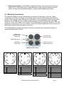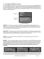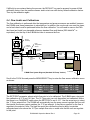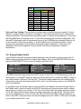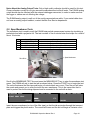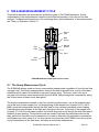
1
For PM10 or PM2.5 Continuous Monitoring
0.14
0.12
ConcRT(15 min)
ConcHr(mg/m3)
0.1
0.08
0.06
0.04
0.02
0
12/16/07
12:00
12/16/07
16:48
12/16/07
21:36
12/17/07
2:24
12/17/07
7:12
12/17/07
12:00
12/17/07
16:48
12/17/07
21:36
12/18/07
2:24
Met One Instruments, Inc.
1600 NW Washington Blvd • Grants Pass, Oregon 97526 • (541) 471-7111 • www.metone.com
12/18/07
7:12
12/18/07
12:00
E-BAM
PARTICULATE MONITOR
OPERATION MANUAL
E-BAM-9800 REV L
Met One Instruments, Inc.
1600 NW Washington Blvd.
Grants Pass, OR 97526
Telephone: (541) 471-7111
Facsimile: (541) 471-7116
www.metone.com
E-BAM Particulate Monitor Operation Manual - © Copyright 2008 Met One Instruments, Inc. All Rights Reserved worldwide.
No part of this publication may be reproduced, transmitted, transcribed, stored in a retrieval system, or translated into any other
language in any form without the written permission of Met One Instruments, Inc.
E-BAM-9800 Operation Manual Rev L
Page 1
Table of Contents
1 INTRODUCTION
4
1.1 About This Manual ......................................................................................................4
1.2 Technical Service........................................................................................................4
1.3 E-BAM: Environmental Beta Attenuation Monitor .......................................................4
1.4 Beta Radiation Safety Statement ................................................................................5
1.5 The E-BAM and U.S. EPA Equivalent Methods ..........................................................5
1.6 E-BAM Specifications .................................................................................................6
2 E-BAM UNIT ASSEMBLY AND START-UP
7
2.1 Assembling the E-BAM ...............................................................................................7
2.2 Electrical Connections ................................................................................................9
2.3 Power-up and Automatic Operation ..........................................................................11
2.4 Power-up Settings Verification and Automatic Self-Test...........................................11
2.5 Filter Tape Loading ...................................................................................................14
2.6 Warm-up Period........................................................................................................15
3 E-BAM USER INTERFACE and MENU SYSTEM
16
3.1 The User Interface - Keypad and Display Functions.................................................16
3.2 Using the Main Sampling Screen..............................................................................17
3.3 Using Main E-BAM Menu System.............................................................................18
4 SAMPLE SITE SELECTION
21
4.1 Site Selection Requirements.....................................................................................21
4.2 Fall Hazard and Security Cautions............................................................................22
4.3 Confined Sampling Locations ...................................................................................22
4.4 Smoke and Ash Monitoring.......................................................................................23
4.5 Remote Monitoring With Solar or Battery Power.......................................................23
5 FIELD CALIBRATIONS AND FLOW CHECKS
25
5.1 Leak Checks and Nozzle/Vane Cleaning..................................................................25
5.2 Ambient Temperature Sensor Audit..........................................................................28
5.3 Ambient Barometric Pressure Sensor Audit..............................................................28
5.4 Flow Audits and Calibrations ....................................................................................29
5.5 Filter RH Sensor Audit ..............................................................................................31
5.6 Filter Temperature Sensor Audit ...............................................................................31
5.7 Pump Tests...............................................................................................................32
5.8 Analog Output Audits ................................................................................................33
5.9 Span Membrane Tests..............................................................................................34
6 THE E-BAM MEASUREMENT CYCLE
36
6.1 The Hourly Measurement Cycle................................................................................36
6.2 The Real-Time Average Measurement Cycle ...........................................................37
6.3 Comparing the Hourly and Real-Time Values...........................................................40
7 SETUP MENU DESCRIPTIONS
41
7.1 The Clock Setup Screen ...........................................................................................41
7.2 The Tape Advance and Real-Time Average Setup Screen ......................................41
7.3 The MACHINE TYPE PM10/PM2.5 Setup Screen ......................................................42
7.4 The Analog Output Setup Screen .............................................................................43
7.5 The Serial Port Setup Screen ...................................................................................43
7.6 The RH Control Setup Screen ..................................................................................44
7.7 The Flow Rate and Flow Type Setup Screen ...........................................................44
7.8 The Ambient RH Sensor Setup Screen ....................................................................45
7.9 The Pump Protection Setup Screen..........................................................................46
E-BAM-9800 Operation Manual Rev L
Page 2
8
9
10
11
12
13
7.10 The Restart Voltage Setup Screen ...........................................................................46
7.11 The STANDARD Temperature Setup Screen...........................................................47
7.12 The Span Membrane Setup Screen..........................................................................47
MAINTENANCE and TROUBLESHOOTING
48
8.1 E-BAM Error Displays, Error Logs, and Error Codes ................................................48
8.2 Contact Closure Alarm Relay Output ........................................................................51
8.3 Basic Problem and Cause/Solution Table.................................................................52
8.4 Met One Suggested Periodic Maintenance...............................................................54
8.5 DC Pump Replacement ............................................................................................55
8.6 Cleaning the Inside of the Sample Nozzle Assembly................................................56
8.7 Cleaning the Beta Detector Assembly ......................................................................57
DATA RETRIEVAL and COMMUNICATIONS
59
9.1 Analog Voltage Output..............................................................................................59
9.2 Serial Port Connections to a Computer.....................................................................59
9.3 Comet™ Data Retrieval Software .............................................................................60
9.4 Downloading Data Using HyperTerminal or other Terminal Programs .....................60
9.5 “AutoMet” Data Retrieval Commands Through the Serial Port .................................61
9.6 Advanced Communications – Escape Commands ...................................................63
9.7 Modem Options for Remote Data Retrieval ..............................................................63
9.8 Flash Firmware Upgrades.........................................................................................64
ACCESSORIES and PARTS
65
10.1 Consumables, Replacement Parts, and Accessories ...............................................65
THEORY OF OPERATION and MATHEMATICAL ANALYSIS
69
11.1 Converting Data Between EPA Standard and Actual Conditions..............................71
SPECIAL E-BAM CONFIGURATIONS
72
12.1 External Pump Box Configurations for the E-BAM....................................................72
12.2 AIRSIS Satellite Uplink Option ..................................................................................73
E-BAM AUDIT SHEET
74
E-BAM-9800 Operation Manual Rev L
Page 3
1 INTRODUCTION
1.1 About This Manual
This document is organized with the most important information toward the front of the manual,
such as site selection, installation, setups, and field calibrations, which all E-BAM owners and
operators should read and understand. Toward the back are sections that provide in-depth
information on subjects such as theory, diagnostics, accessories, and alternate settings. These
sections provide valuable information which should be consulted as needed. Electronic versions of
this manual are also available.
1.2 Technical Service
This manual is structured by customer feedback to provide the required information for setup,
operation, testing, maintaining, and troubleshooting your E-BAM unit. Should you still require
support after consulting your printed documentation, we encourage you to contact one of our expert
Technical Service representatives during normal business hours of 7:00 a.m. to 4:00 p.m. Pacific
Standard Time, Monday through Friday. In addition, technical information and service bulletins are
often posted on our website. Please contact us and obtain a Return Authorization (RA) number
before sending any equipment back to the factory. This allows us to track and schedule service
work and to expedite customer service.
Phone:
(541) 471-7111
Fax:
(541) 471-7116
E-Mail:
[email protected]
Web:
www.metone.com
Address:
Technical Services Department
Met One Instruments, Inc.
1600 NW Washington Blvd.
Grants Pass, OR 97526
1.3 E-BAM: Environmental Beta Attenuation Monitor
The Met One Instruments, Inc model E-BAM automatically measures and records airborne PM10 or
PM2.5 particulate concentration levels using the principle of beta ray attenuation. This method
provides a simple determination of concentration in units of milligrams of particulate per cubic meter
of air. A small 14C (Carbon 14) element emits a constant source of high-energy electrons known as
beta particles. These beta particles are detected and counted by a sensitive scintillation detector. A
vacuum pump pulls a measured amount of dust-laden air through the filter tape, which is positioned
between the source and the detector thereby causing an attenuation of the beta particle signal. The
degree of attenuation of the beta particle signal is used to determine the mass concentration of
particulate matter on the filter tape, and the volumetric concentration of particulate matter in ambient
air. An in-depth scientific explanation of the theory of operation and the related equations is
included toward the back of the manual. Complete descriptions of the measurement cycles are
found in Section 6.
The E-BAM is designed as a simple, compact, and self-contained beta gauge, for portable
applications where rapid deployment and short interval real-time measurements are required.
E-BAM-9800 Operation Manual Rev L
Page 4
1.4 Beta Radiation Safety Statement
The Met One Instruments E-BAM contains a small 14C (Carbon 14) beta radiation-emitting source.
The nominal activity of the source is 60 µCi ±15µCi (microcurries), which is below the “Exempt
Concentration Limit” as defined in 10 CFR Section 30.71 – Schedule B. The owner of an E-BAM is
not required to obtain any license in the United States to own or operate the unit. The owner of an
E-BAM may elect to return the entire unit to Met One Instruments for recycling of the 14C source
when the unit has reached the end of its service life, although the owner is under no obligation to do
so. Under no circumstances should anyone but factory technicians attempt to remove or access the
beta source. The beta source has a half-life of about 5730 years, and should never need to be
replaced unless it becomes damaged or corroded. Neither the 14C source nor the beta particle
detector are serviceable in the field. Should these components require repair or replacement, the EBAM must be returned to the factory for service and recalibration. The E-BAM is manufactured in
compliance with the U.S. NRC safety criteria in 10 CFR 32.27.
1.5 The E-BAM and U.S. EPA Equivalent Methods
The Met One Instruments, Inc. Model E-BAM is not currently designated as a U.S. EPA Federal
Equivalent Method (FEM) for continuous PM10 or PM2.5 monitoring. However, the unit is designed to
accurately predict FRM or FEM concentration measurements when operated in accordance with
this manual. The E-BAM is intended as a rapid-deployment particulate monitor which can be used
for emergency response situations, micro to neighborhood scale particulate studies, perimeter
monitoring, remote monitoring, and other applications where a small, self-contained, portable unit is
required. To that end, the E-BAM is unparalleled in its flexibility and ease of use.
The E-BAM is not intended to be used for permanent, long-term installations at a fixed monitoring
site. This is an application for the Met One Instruments Model BAM-1020, which is an EPA
designated FEM for both PM10 and PM2.5 monitoring, and is intended for continuous operation at a
fixed site. Many agencies have networks which contain both types of Met One BAM units in order to
meet their diverse sampling needs. The following table shows some of the features of the E-BAM
compared to the BAM-1020:
Configurable for PM2.5, PM10, or TSP monitoring:
Compatible with EPA PM10 inlets, cyclones, and WINS impactors:
U.S. EPA PM2.5 and PM10 Federal Equivalent Method:
Portable unit designed for rapid deployment:
Designed for continuous long-term operation at a fixed site:
Hourly concentration measurements:
Hourly concentration accuracy:
Quasi real-time concentration output available:
Analog and digital data outputs available:
16.7 lpm actual or standard flow rate:
Separate weatherproof shelter or enclosure required:
Automatic hourly span checks:
12 volt DC operation for remote sampling:
Meteorological sensor inputs:
Sample RH control:
Filter tape advances:
Operation time per standard filter tape roll:
E-BAM-9800 Operation Manual Rev L
E-BAM
BAM-1020
yes
yes
no
yes
no
yes
good
yes
yes
yes
no
no
yes
yes
yes
variable
variable
yes
yes
yes
no
yes
yes
best
no
yes
yes
yes
yes
no
yes
yes
hourly
60 days
Page 5
1.6 E-BAM Specifications
PARAMETER
SPECIFICATION*
Measurement Principle:
U.S. EPA Designations:
Particulate Concentration by Beta Attenuation.
Designed to meet Class III monitoring criteria. Not an EPA-designated FEM.
Measurement Range:
-0.005 to 65.530 mg/m3 (-5 to 65,530 µg/m3) 16 bit digital range.
± 10% of indicated value for hourly measurements.
1 µg/m3
Accuracy:
Data Resolution:
Lower Detection Limit:†
(2σ, 1 hour measurement)
Lower Detection Limit:†
(2σ, 24 hour average)
Sample Time:
Measurement Cycles:
Flow Rate:
Flow Accuracy:
Pump Type:
Filter Tape:
Span Check:
Beta Source:
Beta Detector Type:
Operating Temp. Range:
Ambient Humidity Range:
Humidity Control:
Approvals:
User Interface:
Analog Voltage Output:
Serial Interface:
Alarm Contact Closures:
Compatible Software:
Error Reporting:
Memory:
Power Supply:
Weight:
Unit Dimensions:
Less than 6.0 µg/m3
Less than 1.2 µg/m3
Continuous air sampling with variable filter change periods.
Automatic hourly concentration measurements, with user selectable 1, 5, 10, 15,
30, or 60 minute quasi-real-time average output.
16.7 liters/minute. Adjustable up to 17.5 lpm. Actual or Standardized flow modes.
±2% of setpoint typical.
Internal DC dual-diaphragm pump standard. 4000 hour rated.
Continuous glass fiber filter, 30mm x 21m roll. Up to 1 year operation per roll.
Manual 800ug (typical) span foil included.
14
C (carbon-14), 60 µCi ±15 µCi (< 2.22 X 10⁶ Beq), Half-Life 5730 years.
Photomultiplier tube with patented scintillator assembly.
-25 to +50°C intermittent. -25 to +40°C continuous.
0 to 90% RH, non-condensing.
Automatic 15 Watt inlet heater module.
CE, NRC, ISO-9001
Menu-driven interface with 4x20 character VFD display and dynamic keypad.
0-1, 0-2.5, or 0-5 volt DC output equals 0-1000 µg/m3. Selectable to represent the
hourly or real-time concentration.
RS-232 2-way serial port for PC, datalogger, or modem communications.
Normally closed contact closure relay output. 0.5A @ 100V DC max.
Comet™ (included), Air Plus™, terminal programs such as HyperTerminal®
Available through serial port, display, and relay output.
4369 records (182 days @ 1 record/hr. 3 days @ 1 record/min).
12 to 16 Volt DC input. 4.1 amps @12 VDC (50 Watts) max continuous draw.
13.2 kg (29 lbs) E-BAM only. 23 kg (50 lbs) with tripod, PM10, 9250, power supply.
41cm high x 36cm wide x 20cm deep. (16” x 14” x 8”).
* Specifications may be subject to change without notice.
† The hourly detection limit is defined as twice the standard deviation of the hourly zero noise of the instrument. The 24 hour
detection limit is defined as the hourly detection limit divided by the square root of 24 (approx 4.9).
E-BAM-9800 Operation Manual Rev L
Page 6
2 E-BAM UNIT ASSEMBLY AND START-UP
This section describes assembly, start-up, and filter tape installation for the E-BAM unit.
2.1 Assembling the E-BAM
The standard DC version of the E-BAM is designed to be field deployable by an average person in
less than 15 minutes under normal conditions. Refer to the photos and diagrams below while
performing the following steps to assemble the unit:
1. Deploy the tripod: Remove the three stainless steel detent pins from the tripod base by
pulling the rings. Unfold the three tripod legs and reinsert the three pins so that each pin
secures a leg in the open position. Make sure the erected tripod is rigid and stable.
Detent Pins
2. Install the E-BAM onto the tripod: Lift the E-BAM assembly and slide the slot on the back
of the E-BAM over the tab on the top of the tripod. Insert the supplied ¼-20 bolt through the
tab on the bottom of the E-BAM and through the hole in the body of the tripod. Secure it with
the supplied washers and nut. This prevents the E-BAM from shifting on the tripod.
3. Install the inlet tube and the PM10 and PM2.5 inlets: Loosen the black weatherproof fitting
on top of the E-BAM and insert the short inlet tube into the top of the unit. The tube must go
through the black fitting and through two o-rings in the top of the E-BAM. Make sure the tube
is fully seated by rotating it back and forth. Tighten the black weatherproof fitting to secure
the inlet tube. For PM10 monitoring, install the BX-802 PM10 inlet directly onto the top of the
short inlet tube. If a BX-807 cyclone is to be used for PM2.5 monitoring, it must be installed
under the PM10 head as shown in the picture below. Lubricate the o-rings as necessary.
Weatherproof
Fitting
Mounting Tab
Bolt
E-BAM-9800 Operation Manual Rev L
Page 7
4. Install the cross-arm and temperature sensor: Connect the 18” cross-arm to the post on
the back of the tripod with the supplied ¾” x ¾” fitting and set screws. The 9250 ambient
temperature sensor snaps onto the cross-arm and plugs into the bottom of the E-BAM.
5. Optional wind sensor: If an optional EX-034 wind speed/direction sensor is supplied, then it
will come with a longer cross-arm tube to use instead of the short one that came with the
temp sensor. Install the wind sensor on one end of the cross-arm, and the temperature
sensor on the other. The wind sensor should be as far from the E-BAM unit as possible, and
the wind vane must be able to rotate fully without hitting anything. Plug the wind sensor into
the corresponding connector on the bottom of the E-BAM. The sensor will need to be
oriented to the north. Consult the separate manual that comes with the 034 wind sensor.
6. Power Supply: Many E-BAMs are supplied with an EX-121 AC-to-12 VDC power supply as
shown in the photo below. Bolt it to one of the legs of the tripod with the included U-bolts.
Plug the power supply output cable into the DC power input on the bottom of the E-BAM.
When the power supply is plugged into AC power, the E-BAM will turn itself on automatically.
Note: If the E-BAM is to be powered by a battery array or solar system, or if the unit is
supplied with an external AC pump box with a built-in power supply, then these items will
plug into the E-BAM power input instead of the normal power supply.
E-BAM-9800 Operation Manual Rev L
Page 8
7. Optional met sensors: If the E-BAM is supplied with other optional met sensors such as
ambient RH or barometric sensors, then these attach to the cross-arm and plug into the
same connector as the temperature sensor, using a supplied splitter junction box.
2.2 Electrical Connections
The standard E-BAM has a set of weatherproof connectors on the bottom of the unit. These
connectors provide the connections for the power supply, external sensors and communications
options. Each connector has a different pin configuration to prevent plugging cables into the wrong
connector. The E-BAM will turn on when a power source is connected to the power input. Note:
There is a 3-color LED located on the bottom of the E-BAM near the electrical connectors. This LED
may flash or hold various colors, but is used for factory test software applications only, and does not
indicate any specific status information to the user.
The E-BAM chassis ground lug should be connected to an earth ground whenever possible, to
reduce electrical noise in the unit.
EX-304 Wind
Speed/Direction
Sensor Input
DC Power Input
(relay output also)
Chassis Ground Lug
Temperature
Sensor Input
RS-232 Comm Port
(analog output also)
E-BAM connector layout
1
1
4
1
5
1
7
5
6
2
6
2
3
2
4
2
3
DC Power Input
Pin
1
2
3
4
Function
+12 VDC Pwr Input
Ground/Common
Alarm Relay IN
Alarm Relay OUT
WS/WD Sensor In
Pin
1
2
3
4
5
Function
Wind Direction Ref.
Ground/Common
Wind Direction Input
Wind Speed Input
Shield
4
3
4
3
Temp Sensor Input
Pin
1
2
3
4
5
6
Function
RH Signal Input
Ground/Common
+12 VDC Output
Temp Signal Input
Baro Signal Input
Shield
E-BAM-9800 Operation Manual Rev L
5
RS-232 Serial Port
Pin
1
2
3
4
5
6
7
Function
RST
RX
TX
Ground/Common
STX
Analog Volt Output
TCK
Page 9
BX-802
PM10 Head
14”
BX-807
PM2.5 Cyclone
(optional)
5”
Inlet Tube
E-BAM Unit
10”
9250
AT Sensor
with cross arm
16”
14”
(Optional EX-034
WS/WD sensor
shown far side)
Total Height:
83” PM10
88” PM2.5
( 8” deep )
9170 Tripod
43”
EX-121
AC to 12 VDC
Power Supply
(optional)
41” triangular
tripod footprint
Standard E-BAM Configuration
Not to scale. Some items simplified for clarity.
E-BAM-9800 Operation Manual Rev L
Page 10
2.3 Power-up and Automatic Operation
The E-BAM is designed to turn on automatically when power is applied. The unit will ask if you are
ready to start, then prompt you to verify several setup menus which are described below. Then the
unit will perform an automatic self-test routine which takes several minutes. After the self-test, the
unit will begin sampling automatically.
Note: If no keypad activity is detected for several minutes after power-up, the E-BAM will
automatically begin sampling based on the existing SETUP options and settings, as long as filter
tape is installed and no hardware or voltage failures are detected. This makes it possible to fully
configure and calibrate the unit in the lab, then simply deploy it to the field and power it up with no
further actions required.
2.4 Power-up Settings Verification and Automatic Self-Test
The E-BAM will prompt you to verify several setup parameters whenever it is powered on. These
setup screens can also be viewed or edited in the SETUP menu under the main E-BAM menu
system. See Section 7 for detailed descriptions of the SETUP parameters.
When power is applied to the E-BAM, the unit will show the firmware revision and unit serial number
for a moment, then display the welcome screen:
WELCOME TO E-BAM
ARE YOU READY TO
START?
YES
Press the YES soft key, and the clock screen is displayed as shown below. If the time and date are
correct, press the YES key. If you need to change the time or date, press NO and the display will
show the time/date set screen. Use the arrow keys to change the values, then press SET. Or press
CONTINUE to go on without making changes.
DATE:
19-NOV-2008
TIME:
16:36:37
IS THIS CORRECT?
NO
YES
19-NOV-2008
16:36:42
SET
CONTINUE
After the time is verified, the unit will display the AVERAGE PERIOD screen shown below. This
menu is important to understand. See Sections 6.2 and 7.2 for detailed descriptions of these
parameters. Press OK if the settings are correct. If the settings need to be changed, press the EDIT
key to enter the edit mode. Select the parameter to be changed with the ◄► keys, and modify the
settings with the ▲▼ keys and press SAVE. Press CONTINUE to exit the edit mode without making
changes.
E-BAM-9800 Operation Manual Rev L
Page 11
LOCATION:
TAPE ADVANCE:
REALTIME AVG:
EDIT
01
24 HRS
10 MIN
OK
LOCATION: 01
TAPE ADVANCE: ▼24 HRS
REALTIME AVG: ▼10 MIN
SAVE
CONTINUE
LOCATION is an ID number which will appear in the data array to indicate which unit collected the
data, and to enable tracking of measurement information. This is used instead of a UNIT ID
because the E-BAM is portable. This may be any number from 01 to 99.
TAPE ADVANCE is how often the E-BAM will automatically advance to a new spot of filter tape.
This value can be set to 1, 2, 3, 4, 6, 8, 12, or 24 hours. The default setting is 24 hours for maximum
tape life. The unit will override this setting and automatically advance the filter tape if the
concentration is too high and the filter tape becomes clogged. If the filter tape is advanced due to
high concentrations, an alarm will be recorded in the alarm log. Note: the tape advance setting does
not change how often the concentration is calculated or stored.
REALTIME AVG is the averaging period for the real-time concentration value. The real-time
concentration measurement is updated every minute, and the REALTIME AVG is the mean of these
real-time values over the selected time period. The REALTIME AVG may be set to the following
time periods: 1, 5, 10, 15, 30, or 60 minutes. This also sets the averaging period for the datalogger.
See Sections 6.2 and 7.2 for important considerations regarding this setting.
After the real-time settings are verified, the E-BAM will go on to display the MACHINE TYPE screen.
Press EDIT to change the setting with the arrow keys, or press OK to go on without changes:
MACHINE TYPE:
< SEE PICTURE
EDIT
PM10
OK
MACHINE TYPE tells the E-BAM which type of inlet it is equipped with, PM2.5 or PM10. The only
difference between the two is weather a PM2.5 cyclone is installed or not. The E-BAM will put the
machine type setting onto the data array, so that you can tell if the collected data was PM2.5 or
PM10. The screen refers the user to a picture located inside the door of the E-BAM for easy
identification of the two possible inlet types:
E-BAM Door Label for Inlet Identification
E-BAM-9800 Operation Manual Rev L
Page 12
After the MACHINE TYPE is set or verified, the E-BAM will raise the nozzle and check to see if the
stainless steel shipping shim is installed under the nozzle. Note: The shim is attached to the unit
with a tether chain, and is also used for the zero portion of the span membrane test. The shim
should be installed any time the E-BAM is shipped or transported in order to prevent nozzle
damage. The unit can sense the shim with a photo sensor. If the shim is still in place the unit will
display the message “PLEASE REMOVE NOZZLE PACKING MATERIAL”.
After the nozzle shim has been removed, the E-BAM will check if a roll of filter tape installed. If tape
is already installed, the unit will go on to the power status screen. If no tape is detected, the unit will
prompt you to install a new roll:
CHECKING FOR
LOADED TAPE.
PLEASE WAIT...
PLEASE LOAD TAPE!
E-BAM WILL NOT
OPERATE WITHOUT
TAPE!
CONTINUE
Install a roll of filter tape as described in Section 2.5. When the filter tape is installed, press
CONTINUE. The unit will again try to detect the tape. If tape is detected, the unit will go on to
display the power status screen. This is mostly useful if the unit is powered with batteries:
BATTERY: 14.3 VOLTS
ESTIMATED OPERATION
TIME FOR 100 AMP-HRS
IS 33 HRS.
CONTINUE
Press CONTINUE to proceed. The unit will begin the self-test process and will show “SELF TEST
RUNNING…” on the display. The self-test takes several minutes and can only be bypassed by
pressing the ESC key. The unit will test the nozzle, tape motor, beta detector, pump, flow sensor,
and pressure sensors. If a fault is detected during the self-test, the hardware failure screen will be
shown. Press CONTINUE to view the cause of the failure. See Section 8.1 for error descriptions. In
the example below, the operator has forgotten to connect the 9250 ambient temperature sensor to
the E-BAM. The unit has indicated that the sensor is not operational. If a hardware failure is
detected, the problem must be corrected before proceeding. Press the MENU key to enter the menu
system if needed. Other hardware failures that will hinder E-BAM operation include:
•
•
•
•
Ambient or filter temperature sensor missing or failed.
Ambient or filter pressure sensor failure.
Broken or missing filter tape.
Low battery voltage or DC input voltage below 10 volts DC.
WARNING
HARDWARE FAILURE
CONTINUE
25-NOV-2008 10:08:00
SENSOR FAILURE
Ambient Temp
-29.6
E-BAM-9800 Operation Manual Rev L
Page 13
If the self-test finishes without errors, the screen will display that the unit is functioning properly.
Press CONTINUE to go on to the start operation screen as shown below. Press YES to immediately
start the E-BAM sampling on a normal operating cycle. Press MENU to forgo operation and enter
the main E-BAM menu system instead.
SELF TEST COMPLETE:
E-BAM FUNCTIONING
PROPERLY.
CONTINUE
WARNING
START OPERATION?
MENU
YES
This is the end of the automatic E-BAM start-up sequence. It is recommended that you perform a
leak check and flow check/calibration as described in Section 5. Become comfortable with these
checks, as they will be performed often.
2.5 Filter Tape Loading
Filter tape must be loaded into the E-BAM for sampling. One roll of tape will last anywhere from a
few weeks to more than a year, depending on the TAPE ADVANCE setting and ambient particulate
levels. It is important to have several spare rolls of tape available to avoid data interruptions. Some
agencies save used rolls of tape for post-sampling analysis, although there is no guarantee that the
sampled spots have not been contaminated. Used filter tape should never be “flipped over” or reused! This will result in measurement problems. Loading a roll of filter tape is a simple matter using
the following steps:
1. If the sample nozzle is in the down position, it will need to be raised. Enter the LOAD TAPE
screen in the main E-BAM menu. The unit will raise the nozzle and prompt you to load the
tape.
2. If you are replacing a used roll of tape. Remove the old roll, then thoroughly clean the nozzle
and vane as described in Section 5.1.
3. An empty core tube must be installed on the left (take-up) reel hub. This provides a surface
for the used tape to spool-up on. Met One supplies a plastic core tube to use with the first roll
of tape. After that, you can use the empty cardboard core tube left over from your last roll to
spool-up the new roll. Never fasten the filter tape directly to the aluminum hub!
4. Load the new roll of filter tape onto the right (supply) reel, and route the tape through the
nozzle area as shown below. Attach the loose end of the filter tape to the empty core tube
with tape.
5. Rotate the tape roll to remove excess slack, then install the plastic spool covers tightly. The
spool covers clamp the tape rolls to the hubs to prevent them from slipping.
E-BAM-9800 Operation Manual Rev L
Page 14
2.6 Warm-up Period
The E-BAM must warm up for at least one hour before optimum accuracy of the concentration data
can be obtained. This is because the beta detector contains a vacuum tube which must stabilize.
This applies any time the unit is powered up after being off for more than a moment. Setups, tests,
and flow calibrations can be performed during this warm up time. The first hour of data should often
be discarded or ignored. Some agencies choose to discard the first few hours of concentration data
after the E-BAM unit is powered up.
E-BAM-9800 Operation Manual Rev L
Page 15
3 E-BAM USER INTERFACE and MENU SYSTEM
This section describes the E-BAM user interface system, and describes the functions of the main
menu options, including how to view data and errors.
3.1 The User Interface - Keypad and Display Functions
The E-BAM user interface consists of a 4x20 character vacuum fluorescent display (VFD) and a
dynamic keypad. The two white keys under the display are called “soft keys”. These are dynamic
keys which change in response to a menu option displayed directly above the key on the bottom
row of the display. The function of these keys depends on which menu is shown on the display, and
are often used for functions such as “save”, “edit”, and “set”.
The four red arrow (cursor) keys are used to scroll up, down, left, and right, to navigate in the menu
system, and to select items or change fields on the screen. The arrow keys are also often used to
change parameters or increment/decrement values in the menu system. The right arrow key can be
used to wake up the display if it has turned off to save power.
The MENU/SELECT key is used to enter the main menu or to select an item in a list. The ESC key
is used to escape or exit out of a menu.
E-BAM
18-NOV-2008
16:55:48
0.038 MG/M3
16:50
0.053 MG/M3 (HR)
SAMPLING...
ESC
MENU
SELECT
PRESS
FOR
DISPLAY
E-BAM User Interface
E-BAM-9800 Operation Manual Rev L
Page 16
3.2 Using the Main Sampling Screen
The E-BAM display shows the Sampling screen when the unit is in normal operation. The active
display area shows the current date and time, the latest real-time average concentration, and the
last hourly concentration. Also shown is a status message, such as “SAMPLING…”. To view the
rest of the instantaneous sensor parameters which do not all fit on the display at once, press the
down ▼ arrow. The date and time will remain at the top of the display at all times.
To view past data, use the left ◄ arrow key to scroll back to previous data records. There will be
one complete data record for every real-time average interval, indicated by the time/data stamp at
the top of the screen. For example, if the real-time average is set to 10 minutes, then there will be a
complete data record stored every 10 minutes as shown below. Again, you can use the ▼ key to
view the rest of the sensor parameters for that record. Press the ESC key at any time to return to
the current concentration sampling screen.
Scroll left◄ to view past data records
Real-Time Avg.
Concentration
Hourly
Concentration
18-NOV-2008 16:50:00
0.038 MG/M3
16:50
0.053 MG/M3
(HR)
18-NOV-2008 16:55:48
0.038 MG/M3
16:50
0.053 MG/M3
(HR)
SAMPLING...
Visible display area
showing current
parameters
18-NOV-2008
FLOW:
WS:
WD:
AT:
FT:
RHi:
RHx:
BV:
18-NOV-2008
FLOW:
WS:
WD:
AT:
FT:
RHi:
RHx:
BV:
Scroll down ▼ to view
the other current
sensor parameters
16:50:00
16.7 LPM
0.0 M/S
0 DEG
24.5 C
27.2 C
33 %
0 %
14.1 V
16:55:48
16.7 LPM
0.0 M/S
0 DEG
24.3 C
26.1 C
34 %
0 %
14.1 V
Main Sampling Screen Format
Below is a table which describes the other parameters visible in the main sampling display as
shown above. In addition to the hourly and real-time average concentrations, these are all of the
logged parameters in the E-BAM:
Parameter
FLOW
WS
WD
AT
FT
RHi
RHx
BV
FLOW
Description
Primary air flow rate in actual LPM or standard SLPM.
Wind speed in meters per second (if equipped).
Wind direction in degrees (if equipped).
Ambient temperature in degrees C.
Filter temperature in degrees C.
Internal filter RH.
External ambient RH (if equipped).
Battery voltage (or DC input voltage).
Secondary flow in LPM. Only appears if primary flow is set to SLPM.
E-BAM-9800 Operation Manual Rev L
Page 17
3.3 Using Main E-BAM Menu System
The main E-BAM menu system can be entered at almost any time by pressing the MENU/SELECT
key. Use the ▲▼ arrow keys to select the desired menu option, then press the MENU/SELECT key
to enter the selected sub-menu. The functions in the FIELD CALIBRATION menu are described in
Section 5. The functions in the SETUP menu are described in Section 7. All of the other main menu
functions are described below.
Visible display
area
OPERATE
LOAD TAPE
SETUP
▼MEMORY
Scroll down ▼
to view these
options
SELF TEST
■FIELD CALIBRATION
SHUTDOWN/SHIPPING
VIEW ALARM LOG
ABOUT
The Main E-BAM menu
OPERATE: This menu option starts the E-BAM into normal operation mode and starts a new
sample cycle. You will see a message which says” WARNING: START OPERATION?” Press the
YES key to start a new sample. If the unit is already sampling, this option will simply exit the main
menu and display the main sampling screen.
LOAD TAPE: This menu option is used for filter tape installation. If this option is selected, the EBAM will simply raise the sample nozzle for easy tape loading, then display “PLEASE LOAD TAPE.”
Load the tape and press the CONTINUE key to go back to the main menu.
SETUP: This is the setup menu for the E-BAM. All of the setup parameters in this menu are
described in Section 7.
MEMORY: This menu option displays the amount of memory left in the E-BAM digital data system
as shown below. To erase the memory, press the CLEAR key. Use the arrow keys to select either
the DATA LOGGER or ALARM LOG to be cleared, then press the CLEAR key again. The unit will
show a CAUTION screen. If you are sure you want to erase the selected log, press the YES key.
CAUTION! Once the data log or the error log is cleared, the erased data can never be
recovered.
MEMORY
99 % REMAINING
30.3 DAYS REMAINING
CLEAR
EXIT
CLEAR MEMORY
CLEAR:▼DATA LOGGER
CLEAR
EXIT
>>>>> CAUTION <<<<<
CLEAR DATA LOGGER
MEMORY?
NO
YES
The unit contains memory for 4369 data records. The memory will fill up faster the shorter the realtime average interval is set to, as shown in the table below. This is another reason why the 1 and 5
E-BAM-9800 Operation Manual Rev L
Page 18
minute RT averages are rarely used. Note: When the memory is full, the unit over-writes the
oldest data.
Real-Time
Average
Setting
1 min
5 min
10 min
15 min
30 min
60 min
Records
Stored
Per Hour
60
12
6
4
2
1
Memory
Capacity
(Days)
3.03
15.1
30.3
45.5
91
182
SELF TEST: This menu option starts the E-BAM on an automatic self-test cycle, just like the selftest it performs when powered on. Press the ESC key to escape from the self-test and return to the
main menu.
FIELD CALIBRATION: This is the field calibration menu for the E-BAM. All of the calibrations and
tests in this menu are described in Section 5.
SHUTDOWN / SHIPPING: This menu option is used to prepare the E-BAM for transport. When
you enter this screen, the nozzle will raise, and the display will show “PLEASE INSERT NOZZLE
PACKING MATERIAL”. This is the empty zero membrane shim which is connected to the unit with a
tether chain. This shim prevents damage of the nozzle during transport or shipment. Insert the shim
under the nozzle with the tab extending through the slot. The E-BAM will automatically lower the
nozzle onto the shim, then display: “OK TO TURN OFF E-BAM”. The power cord can now be
unplugged to power off the E-BAM. Note: It is OK to power off the E-BAM at almost any time during
normal operation. This menu simply allows the opportunity to insert the nozzle shim.
VIEW ALARM LOG: This menu option allows you to quickly view the error log entries in the EBAM without having to download the digital data. The screen will display the type or error, as well as
the time and date when the error occurred. Scroll through the error records using the ◄► arrow
keys. Press the MENU/SELECT key to return to the main menu.
ABOUT: This menu option displays the E-BAM firmware version and revision, as well as the EBAM serial number as shown in the example below. The up/down arrow keys may be pressed to
change which firmware version is shown. The E-BAM has two separate firmware files. One is for the
master CPU and the other is for the 3610 I/O control board. Press the MENU/SELECT key to return
to the main menu.
3613-01 R1.50.5
SN: F1768
Met One Instruments
www.metone.com
E-BAM-9800 Operation Manual Rev L
Page 19
Note: If the ESC key is pressed while the E-BAM is displaying the ABOUT screen, the unit will
prompt the user for a password. This is for entry into an advanced factory test menu. Do not enter
this system unless instructed to do so by a Met One technician.
Password (000■)
E-BAM-9800 Operation Manual Rev L
Page 20
4 SAMPLE SITE SELECTION
Use the following criteria when deciding on a sampling location for the E-BAM. Always consider the
safety and security of the unit as well as the suitability of the sampling environment.
4.1 Site Selection Requirements
Selection of a proper site for the E-BAM is critical for accurate measurements. In many cases, these
items must be correctly addressed in order for the collected data to be acceptable for regulatory
requirements, such as FEM, ARM or SPM methods. U.S. EPA Specifications for the site selection
can be found in the EPA documents listed below:
•
•
40 CFR, Part 58 Appendix E.
Quality Assurance Guidance Document 2.12 “Monitoring PM2.5 in Ambient Air Using
Designated Reference or Class I Equivalent Methods” Section 5.1.2.
The following is a summary of the primary site requirements. In any case, the Code of Federal
Regulations takes precedence where applicable. Refer to the EPA website at www.epa.gov .
Inlet Height:
• The inlet should be located in the “breathing zone”, between 2 and 15 meters above ground
level. When installed on the standard tripod, the E-BAM PM10 inlet is positioned just over two
meters above the ground or other mounting surface. A PM2.5 cyclone will add about five
inches.
• If the inlet is located on (or through) a rooftop, the total height should be no more than 15
meters from the ground level.
• If the BAM-1020 is to be co-located with other particulate instruments, such as FRM filtertype samplers or other BAM units, then the air inlet must be the same height as the inlet of
the other samplers, within one meter vertically. Within one foot is preferred.
• If the E-BAM inlet is the highest point on a building, then lightning rods must be installed to
prevent destruction of the unit during electrical storms.
Inlet Radius Clearance:
• The E-BAM inlet must have a one meter radius free of any objects that may influence airflow
characteristics, including the inlet of another instrument.
• If a E-BAM is to be co-located at a station with other BAM or FRM sampler, the inlets of each
sampler must be no less than one meter apart from each other, and no more than four
meters apart. Two meter spacing is recommended where possible.
• If installed near a PM10 Hi-Volume sampler, then the distance between the inlet of the E-BAM
and the Hi-Vol must be no less than two meters.
• The E-BAM inlet must be located away from obstructions such as short walls, fences, and
penthouses, so that the inlet is unobstructed for two meters in all directions.
• If located beside a major obstruction (such as a building) then the distance between the EBAM and the building must be equal to twice the height of the building.
• The inlet must be at least 20 meters from the drip line of any overhanging trees.
• There must be at least a 270 degree arc of unrestricted airflow around the inlet. The
predominant direction of concentration movement during the highest concentration season
must be included in the 270 degree arc.
E-BAM-9800 Operation Manual Rev L
Page 21
Artificial Particulate Sources:
To avoid possible errors in the concentration measurements, the inlet must be located as far as
possible from any artificial sources of particulate, such as blowers, vents, or air conditioners on a
rooftop. Especially if any of these types of devices blow air across the inlet of the E-BAM. Even
sources of filtered air must not blow across the inlet.
Spacing from Roadways:
The E-BAM should usually not be located directly next to a major highway or arterial roadway, as
vehicle exhaust will dominate the concentration measurement. This effect can be difficult to predict
accurately as shifting winds may direct the plume toward or away from the E-BAM inlet.
•
•
•
•
Roads with a daily traffic volume of less than 3,000 vehicles are generally not considered
major sources of pollutants, and in this case the E-BAM must be located at least five meters
from the nearest traffic lane.
The E-BAM must be located at least 25 meters from any elevated roadway greater than five
meters high.
The unit should be located as far as possible from unpaved roadways, as these also cause
artificial measurements from fugitive dust.
The unit should not be installed in unpaved areas unless year-round vegetative ground cover
is present, to avoid the affects of re-entrained fugitive dust.
4.2 Fall Hazard and Security Cautions
If the E-BAM is to be installed more than three meters above ground level, then the tripod legs must
be bolted down to prevent the unit from falling to the ground. An accidental fall of more than three
meters may compromise the containment of the radioactive source and the unit will need to be
returned to the factory for testing. In addition, dropping the E-BAM from any height will cause a
potential safety hazard for those below, and may damage the unit beyond repair.
The E-BAM tripod should be secured to the mounting surface in windy conditions to prevent the unit
from falling over, even at ground level. This is especially important in winds over 30 mph. If boltdown is not possible, then the tripod legs may be weighted down with sand bags to secure the unit.
Wind or fall damage is not covered under warranty.
The E-BAM should be secured from theft or vandalism to the extent possible. A limited-access
rooftop or a fenced lot are often good places to deploy the unit. Solar panels and batteries are also
highly susceptible to theft and should be secured.
4.3 Confined Sampling Locations
Because of the portable nature of the unit, the E-BAM is sometimes deployed in confined or nonambient locations to monitor highly localized particulate sources, such as tunnels, mines, quarries,
shopping malls, train stations, etc. Each of these applications are unique and present various
challenges. We recommend that you contact a Met One Service representative to determine the
suitability of the unit if you plan a custom deployment like this.
E-BAM-9800 Operation Manual Rev L
Page 22
4.4 Smoke and Ash Monitoring
A primary design use for the standard E-BAM is for tracking smoke and ash plumes from wildfires,
prescribed burns, agricultural burns, and even volcanic activity. In these cases, the unit is often
sited at the outskirts of a populated area in the expected path of the smoke plume. The unit is
usually equipped with the optional EX-034 wind speed and direction sensor for these applications,
in order to correlate changing wind patterns with particulate events. The wind sensor is plug-andplay, and only requires an extended cross-arm for the tripod mount. The EX-034 will need to be
oriented to the north for accurate wind direction measurements.
In smoke tracking applications, the filter tape may be consumed at a much faster rate than normal.
This is because the E-BAM may automatically advance the filter to a new spot if the particulate
loading becomes excessive, regardless of the user-defined tape advance setting. This is based
on the measured pressure drop across the filter tape. This feature protects the pump, preserves
accurate flow control, and prevents damage to the filter tape.
4.5 Remote Monitoring With Solar or Battery Power
The standard version of the E-BAM is designed to be deployable in remote areas where AC power
is not available. These applications require deep-cycle batteries, and sometimes a solar panel array
as well. The E-BAM is rated for a worst-case continuous power draw of 50 Watts (approximately 4.1
amps at 12 volts DC).
Battery Operation:
The simplest method for remote deployment is to use batteries. The most common type for this
application are 12 volt, 110 amp-hour, gel-cell or AGM, deep cycle batteries. The E-BAM is supplied
with a battery cable which plugs into the power connector on the bottom of the unit. The other end
connects to the battery terminals. The batteries are typically enclosed in a plastic box on the ground
near the E-BAM.
Assuming a continuous E-BAM current draw of 4.1 amps, a single fully-charged 110Ah battery
would have the theoretical capacity to run the unit for 26.8 hours. However, the general rule is that a
lead-acid battery should not be discharged by more than 2/3 of its capacity, especially in
temperatures below 40 degrees F, so:
((110Ah / 4.1A) * .67) = 18.0 hours of run time per battery.
Additional run time is achieved by connecting more batteries in parallel to the first battery.
Additional batteries must be of the same type! A set of three fully charged 110Ah batteries in
parallel should run an E-BAM for at least 54 hours under worst-case conditions. When the battery
voltage discharges below 10.0 volts, the unit will shut itself down until fresh batteries are supplied
and the restart voltage threshold is exceeded. See Section 7.10.
Solar Operation:
Some remote applications require operating the E-BAM with a solar array. Care must be taken to
ensure that the solar array is designed correctly, and is specified to meet the power requirements or
the unit. Many people greatly underestimate the amount of solar wattage required to run a particular
load continuously year-round. If the solar array is not large enough, the batteries will eventually
become depleted and the E-BAM will shut down. The size of the solar array will vary depending on
the Peak Sun-Hour (PSH) rating of the sample location. PSH ratings are usually based on worst
E-BAM-9800 Operation Manual Rev L
Page 23
case winter conditions at a particular location. Summer sun ratings at the same location will be
considerably higher. Sun rating maps can be found on the National Renewable Energy Laboratory
website at www.nrel.gov. The table below shows some estimated solar array wattages required to
run a 50 Watt DC E-BAM continuously in various sun ratings:
Local PSH
Sun Rating
kWh/m2/day
2.0
2.5
3.0
3.5
4.0
4.5
5.0
5.5
6.0
6.5
7.0
Minimum
Solar Array
Wattage
1010
810
675
580
500
450
400
370
340
310
290
Battery
Array for 5
Days Backup
7 x 110Ah
7 x 110Ah
7 x 110Ah
7 x 110Ah
7 x 110Ah
7 x 110Ah
7 x 110Ah
7 x 110Ah
7 x 110Ah
7 x 110Ah
7 x 110Ah
A bank of parallel batteries is required to run the E-BAM when using a solar array, to ensure
function during the night and cloudy weather. The solar panels must be wired to charge the
batteries through an appropriate charge controller. The E-BAM runs off of the battery pack only.
Never connect a solar panel directly to the E-BAM power input! The E-BAM will be immediately
damaged because solar panels output a high DC voltage during sunlight hours. The E-BAM will only
run on 12 to 16 VDC. Ensure that the charge controller output does not exceed 16 volts when
connected to the battery pack, or damage to the E-BAM can result.
A solar array for the E-BAM tends to end up being fairly large, heavy, and expensive. It is usually
easiest and cheapest to contact your local solar shop for help in building the array. You may also
contact a service representative at Met One for assistance. Met One Instruments can also supply
complete E-BAM solar systems on a custom order basis.
Solar Panel
Array
Solar Charge
Controller
Battery
Array
E-BAM
Simplified E-BAM Solar System Block Diagram
E-BAM-9800 Operation Manual Rev L
Page 24
5 FIELD CALIBRATIONS AND FLOW CHECKS
This section describes the audit and calibration process for the E-BAM flow system, ambient
temperature sensor, barometric pressure sensors, filter sensors, analog output, and span
membrane. The most important maintenance parameters are the leak checks, nozzle/vane
cleaning, and flow checks! The audit screens for the parameters described here are all found in
the FIELD CALIBRATION menu under the main E-BAM menu as shown below:
Visible display
area
OPERATE
LOAD TAPE
SETUP
▼MEMORY
Scroll down ▼
to view these
options
SELF TEST
■FIELD CALIBRATION
SHUTDOWN/SHIPPING
VIEW ALARM LOG
ABOUT
The main E-BAM menu
■TEMPERATURE
PRESSURE
FLOW
▼FILTER RHi
Scroll down ▼
to view these
options
FILTER TEMPERATURE
PUMP TEST
ANALOG AUDIT
MEMBRANE TEST
The FIELD CALIBRATION menu
5.1 Leak Checks and Nozzle/Vane Cleaning
The E-BAM flow system must be checked for leaks before any flow calibrations are performed.
Scroll to the PUMP TEST line and press the MENU/SELECT key to enter the leak test and pump
test menu. The pump will turn on automatically when this screen is entered:
MODE:▼LEAK TEST
FLOW:
0.1 LPM
PRES: 732.3 mmHg
EXIT
The MODE parameter selects either the LEAK TEST or the PUMP TEST mode. The LEAK TEST
mode is used to check for flow leaks and to measure the leakage at the filter tape nozzle interface.
The PUMP TEST mode is used to test the capacity of the pump to determine when it needs to be
replaced.
E-BAM-9800 Operation Manual Rev L
Page 25
The FLOW parameter is the instantaneous output from the unit’s internal flow sensor. This is the
parameter that you are auditing. The PRES parameter is not used during the leak test.
Perform the leak check as follows:
1. Verify that a fresh spot of tape is located beneath the nozzle. If the tape is damaged it may
be difficult to pass the leak check.
2. Remove the PM10 head from the inlet tube. Install a BX-305 leak test valve (or equivalent
valve for leak checking FRM samplers) onto the inlet tube. Turn the valve to the OFF position
to prevent any air from entering the inlet tube. If a PM2.5 inlet cyclone is used, it is usually
best to install the leak valve above the cyclone in order to test it for leaks as well.
3. Enter the PUMP TEST screen as described above, and set the MODE to LEAK TEST. The
pump should turn on automatically and ramp up to full speed.
4. The flow rate should drop below 1.0 lpm. If the leak value is greater than 1 lpm, then the
nozzle and vane need cleaning, or there may be another leak somewhere in the system.
5. Resolve the leak and perform the check again. A properly functioning E-BAM with a clean
nozzle and vane will usually have a leak value of about 0.6 lpm or less using this method,
depending on the type of pump used.
6. When finished, exit the TEST PUMP menu, remove the leak test valve, and re-install the inlet
heads.
Important Notes About Leak Checks:
Leak checks should be performed at least monthly and whenever the filter tape is changed. Almost
all air leaks in the E-BAM system occur where the nozzle contacts the filter tape. The E-BAM has
no way of automatically detecting a leak at this interface! This is because the airflow sensor is
located downstream of the filter tape. There will normally be a small amount of leakage at the tape,
but an excessive leak lets an unknown amount of air enter the system through the leak instead of
the inlet. This will cause the air volume calculation and the concentration measurement to be
incorrect. Allowing a leak to persist may cause data to be invalidated back to the last known
good leak check.
The 1.0 lpm leak check allowance is due to the test conditions. With the inlet shut off, the vacuum in
the flow system is several times greater than during normal sampling, which exaggerates any leaks.
If the leak reading during this test is less than 1.0 lpm, there should not be a significant leak during
normal operation.
Some agencies choose to adopt tighter tolerances for the leak test, such as requiring a leak value of
0.5 lpm or less after the nozzle and vane are cleaned. Most agencies perform as-found leak checks
(before cleaning the nozzle and vane) for data validation purposes. The typical recommended
threshold for invalidating data is an as-found leak value (before cleaning nozzle and vane) of 1.5
lpm or higher. Again, some agencies adopt tighter standards, such as invalidating data if the asfound leak value is greater than 1.0 lpm.
Nozzle and Vane Cleaning:
The nozzle and vane (located under the tape) must be cleaned regularly to prevent leaks and
measurement errors. The cleaning must be done at least each time the filter tape is changed,
though monthly cleaning is highly recommended. Some sites will require more frequent cleaning as
determined by the site administrator. The worst environment for nozzle contamination seems to be
hot, humid environments. This is because damp filter tape fibers more easily stick to the nozzle and
E-BAM-9800 Operation Manual Rev L
Page 26
vane. The fibers can quickly build up, creating air leaks or punching small holes in the filter tape
which will cause measurement errors. Use the following steps to clean the parts:
1. It is advisable to perform an as-found leak check before cleaning the nozzle, in order to
validate past data as being leak-free.
2. If the nozzle is down, raise it by entering the LOAD TAPE screen in the main E-BAM menu.
The nozzle will automatically raise.
3. Remove the filter tape (if installed) from the nozzle area so that you have access to the vane.
4. Thoroughly clean the nozzle sealing surface and the vane crosshairs with a cotton-tipped
applicator and isopropyl alcohol. Any hardened deposits may have to be carefully scraped off
with the wooden end of the applicator.
5. Inspect the nozzle lip and vane for any burrs which may cause leaks or tape damage.
6. After the cleaning process, it is recommended to use canned dusting air to blow down
through the vane crosshairs. This removes any filter debris from the face of the beta detector,
which is located directly under the vane. Be careful not to damage the beta detector window!
7. Reinstall the filter tape and perform a final leak check.
Tape
Support
Vane
E-BAM
Sample
Nozzle
Cleaning the E-BAM nozzle and Vane with a cotton-tipped applicator
The figure below shows the difference between good and bad filter tape spots. The tape on the right
is from an E-BAM with a clean nozzle and vane. The particulate spots have crisp edges, are
perfectly round, and are evenly distributed. The tape on the left is from a unit with a dirty vane. A
spot of debris has built up, and is punching a pin-hole at the edge of each spot. The spots also
show a “halo” effect from an air leak because the debris has built up to the extent that the nozzle no
longer seals correctly. These faults are easily prevented by keeping the nozzle and vane clean.
E-BAM Filter Tape Examples
E-BAM-9800 Operation Manual Rev L
Page 27
5.2 Ambient Temperature Sensor Audit
The ambient temperature must be audited or calibrated before any flow calibrations are performed.
Scroll to the TEMPERATURE line and press the MENU/SELECT key to enter the ambient
temperature sensor calibration menu:
POINT:▼HIGH
E-BAM: 23.6 C
REF: 23.9 C
CALIBRATE
DEFAULT
POINT:▼LOW
E-BAM: -10.2 C
REF: -10.8 C
CALIBRATE
DEFAULT
The POINT parameter selects either the HIGH or LOW calibration point. The HIGH point is the
normal ambient calibration point which is used for all field calibrations. The LOW point is only used
for laboratory ice-bath calibrations of the ambient temperature sensor. Select HIGH to perform an
ambient temperature sensor calibration.
The E-BAM parameter is the instantaneous output from the unit’s ambient temperature sensor. This
is the parameter that you are auditing.
The REF parameter is the field where you enter the correct temperature as shown on your traceable
reference standard temperature audit device. After you have entered the correct temperature using
the arrow keys, press the CALIBRATE key to correct the E-BAM sensor reading. The E-BAM and
REF parameters should now match. Press the ESC key when finished.
If difficulty is encountered during the process, the DEFAULT key can be pressed to erase all field
calibration factors from the temperature sensor and to start over with factory default calibration
factors. Then try the calibration again.
5.3 Ambient Barometric Pressure Sensor Audit
The ambient barometric pressure sensor must be audited or calibrated before any flow calibrations
are performed. Scroll to the PRESSURE line and press the MENU/SELECT key to enter the
ambient pressure sensor calibration menu:
PRESSURE
E-BAM: 732.8 mmHg
REF: 737.9 mmHg
CALIBRATE
DEFAULT
The E-BAM parameter is the instantaneous output from the unit’s ambient barometric pressure
sensor. This is the parameter that you are auditing.
The REF parameter is the field where you enter the correct pressure as shown on your traceable
reference standard barometric pressure audit device. After you have entered the correct pressure
using the arrow keys, press the CALIBRATE key to correct the E-BAM sensor reading. The E-BAM
and REF parameters should now match. Press the ESC key when finished.
E-BAM-9800 Operation Manual Rev L
Page 28
If difficulty is encountered during the process, the DEFAULT key can be pressed to erase all field
calibration factors from the pressure sensor and to start over with factory default calibration factors.
Then try the calibration again.
5.4 Flow Audits and Calibrations
The flow calibration is performed after the temperature and pressure sensors are audited, because
the E-BAM uses these parameters to calculate flow. In addition, the nozzle and vane must be clean,
and a leak check must be performed before the flow calibration. You will need to remove the PM10
®
inlet head and install your traceable reference standard flow audit device (BGI deltaCal or
equivalent) onto the top of the E-BAM inlet tube to measure the flow.
Nozzle
Assembly
Ambient
Pressure
Port
Filter
Temperature
Sensor
Filter RH
Sensor
Mass Flow Sensor
Detector
Block
Filter
Pressure
Port
Surge
Filters
Debris
Filter
Internal DC
Pump
E-BAM Flow System Diagram (Standard DC Pump Version)
To Exhaust
Scroll to the FLOW line and press the MENU/SELECT key to enter the flow sensor calibration menu
as shown:
SETPOINT:▼17.5 LPM
E-BAM: 17.5 LPM
REF: 17.4 LPM
CALIBRATE
DEFAULT
SETPOINT:▼14.0 LPM
E-BAM: 14.0 LPM
REF: 14.1 LPM
CALIBRATE
DEFAULT
SETPOINT:▼16.7 LPM
E-BAM: 16.7 LPM
REF: 16.6 LPM
EXIT
The SETPOINT parameter selects which flow point is to be calibrated. The E-BAM uses a two-point
flow calibration at 17.5 and 14.0 lpm. The 16.7 lpm point can only be audited, not calibrated. Notice
that there is no CALIBRATE option when the SETPOINT is set to 16.7. Use the arrow keys to select
the 17.5 lpm setpoint first. The E-BAM will automatically turn the pump on and regulate the flow until
the internal flow sensor output matches the 17.5 lpm setpoint. It may take a moment for the flow to
regulate to the setpoint. Note: The high flow point also verifies the pump’s ability to maintain
adequate head room above the 16.7 lpm sample flow rate, so make sure that the unit can regulate
to this point.
E-BAM-9800 Operation Manual Rev L
Page 29
The E-BAM parameter is the instantaneous output from the unit’s internal flow sensor. This is the
parameter that you are auditing.
The REF parameter is the field where you enter the correct flow as shown on your traceable
reference standard flow audit device. After you have entered the correct flow using the arrow keys,
press the CALIBRATE key to correct the E-BAM sensor reading. The E-BAM should then reregulate the flow to the setpoint, and the E-BAM and REF parameters should match.
Set the SETPOINT to 14.0 lpm and repeat the calibration process. After the 17.5 and 14.0 lpm
points are calibrated, select the 16.7 lpm setpoint and verify that the E-BAM flow and the flow from
your traceable standard match within 0.1 lpm. Press the ESC key to exit the flow calibration menu
when finished.
If difficulty is encountered during the process, the DEFAULT key can be pressed to erase all field
calibration factors from the flow sensor and to start over with factory default calibration factors. Then
try the calibration again.
To audit the flow system without performing any calibrations, simply select the 16.7 lpm setpoint
without calibrating the other setpoints first. Allow the E-BAM flow to regulate to the setpoint, then
compare the E-BAM flow reading to your traceable standard and record the results. If the audit
device flow and the E-BAM flow differ by 4% (about 0.67 lpm) or more, then a full flow calibration
must be performed. Most agencies adopt tighter standards. Met One recommends that the flow be
maintained within ±0.2 lpm, which is well within the units capabilities.
Flow Calibrations on E-BAMs Operated in STANDARD Flow Type: If your E-BAM is set to
report in EPA Standard flow conditions instead of actual (volumetric) flow conditions, then the flow
reading in the FLOW calibration screens shown above will indicate SLPM instead of LPM. It is
critical that the flow type of your traceable flow audit device matches the flow type of the EBAM. Flow calibration on E-BAM units operated in STANDARD flow mode can be done a couple of
different ways:
•
•
•
The easiest method is to simply use a traceable flow audit device which reports STANDARD
flow values, such as the BGI deltaCal which reports both STANDARD (Qs) and ACTUAL (Qa)
flow.
The second option is to change the FLOW TYPE from STANDARD to ACTUAL in the E-BAM
SETUP menu, then perform a regular flow calibration as described above. If this method is
used, be sure to set the unit back to STANDARD flow when finished.
The third option is to convert the ACTUAL flow output from your traceable reference flow
meter to STANDARD conditions (Qs) using a formula:
Qs = Qa * (Pa / Ta) * (298 / 760)
Ta = Ambient Temperature Kelvin (Kelvin = Celsius + 273)
Pa = Ambient Barometric Pressure (mmHg)
Qa = Actual Volumetric Flow from Reference Meter
E-BAM-9800 Operation Manual Rev L
Page 30
5.5 Filter RH Sensor Audit
The filter relative humidity sensor is used to measure the humidity of the sample air and to control
the inlet heater to prevent moisture from being sampled as particulate mass. Scroll to the FILTER
RHi (RH internal) line and press the MENU/SELECT key to enter the filter RH sensor calibration
menu:
FILTER RHi
E-BAM: 32 %
REF: 35 %
CALIBRATE
DEFAULT
The E-BAM parameter is the instantaneous output from the unit’s filter RH sensor. This is the
parameter that you are auditing.
The REF parameter is the field where you enter the correct RH as shown on your traceable
reference standard relative humidity audit device. After you have entered the correct RH using the
arrow keys, press the CALIBRATE key to correct the E-BAM sensor reading. The E-BAM and REF
parameters should now match. Press the ESC key when finished.
If difficulty is encountered during the process, the DEFAULT key can be pressed to erase all field
calibration factors from the RH sensor and to start over with factory default calibration factors. Then
try the calibration again.
Important Note: It is often difficult to calibrate the sensor if the E-BAM is warm, as the heating of
the unit will reduce the sample RH (as it should) making it difficult to compare the E-BAM filter RH
reading to an ambient RH traceable standard reading. If the sensor is to be calibrated, it is best to
do it when the E-BAM is cold (equilibrated to ambient) and the nozzle is lifted up. It is recommended
to leave the sensor at the factory default calibration. The E-BAM filter RH sensor is only a ±4%
device when functioning properly, and will typically read a completely unreasonable value if it fails,
such as 135% or -25%.
5.6 Filter Temperature Sensor Audit
The filter temperature sensor is used to measure the temperature of the sample air and to monitor
the function of the inlet heater. Scroll to the FILTER TEMPERATURE line and press the
MENU/SELECT key to enter the filter temperature sensor calibration menu:
FILTER TEMPERATURE
E-BAM: 23.8 C
REF: 24.6 C
CALIBRATE
DEFAULT
The E-BAM parameter is the instantaneous output from the unit’s filter temperature sensor. This is
the parameter that you are auditing.
The REF parameter is the field where you enter the correct temperature as shown on your traceable
reference standard temperature audit device. After you have entered the correct temperature using
E-BAM-9800 Operation Manual Rev L
Page 31
the arrow keys, press the CALIBRATE key to correct the E-BAM sensor reading. The E-BAM and
REF parameters should now match. Press the ESC key when finished.
If difficulty is encountered during the process, the DEFAULT key can be pressed to erase all field
calibration factors from the temperature sensor and to start over with factory default calibration
factors. Then try the calibration again.
Important Note: It is often difficult to calibrate the sensor if the E-BAM is warm, as the heating of
the unit will increase the sample temperature (as it should) making it difficult to compare the E-BAM
filter temperature reading to an ambient temperature traceable standard reading. If the sensor is to
be calibrated, it is best to do it when the E-BAM is cold (equilibrated to ambient) and the nozzle is
lifted up. It is recommended to leave the sensor at the factory default calibration. The E-BAM filter
temperature sensor very rarely fails.
5.7 Pump Tests
The E-BAM pump should be periodically tested to ensure it has sufficient vacuum capacity for
normal operation. Scroll to the PUMP TEST line and press the MENU/SELECT key to enter the leak
test and pump test menu. The pump will turn on automatically when this screen is entered:
MODE:▼PUMP TEST
FLOW:
14.3 LPM
PRES: 398.3 mmHg
EXIT
The MODE parameter selects either the LEAK TEST or the PUMP TEST mode. The PUMP TEST
mode is used to test the capacity of the pump to determine when it needs to be replaced.
The FLOW parameter is the instantaneous output from the unit’s internal flow sensor.
The PRES parameter is the filter pressure reading which indicates the vacuum beneath the filter
tape. This is used to measure the vacuum capacity of the pump during the pump test.
Perform the pump test as follows:
1. Remove the PM10 head and install the BX-305 leak test valve onto the inlet tube. Turn the
valve to the OFF position to prevent any air from entering the inlet tube.
2. Enter the PUMP TEST screen as described above, and set the MODE to LEAK TEST. The
pump should turn on automatically and ramp up to full speed.
3. Very slowly open the leak check valve on the inlet just a small amount, so that the FLOW
reading on the E-BAM display increases to between 14 and 15 lpm, with the pump still at full
speed. Allow the flow reading to stabilize.
4. Compare the PRES (vacuum) value from the E-BAM display to the chart below for the
particular flow rate. The PRES value should be less than or equal to the values in the chart. If
the PRES value on the E-BAM display is higher than the “poor” value in the chart at that
particular flow rate, then the E-BAM pump may need to be replaced.
E-BAM-9800 Operation Manual Rev L
Page 32
Flow
Rate
14.0
14.1
14.2
14.3
14.4
14.5
14.6
14.7
14.8
14.9
15.0
Vacuum Measurement Value
Good
390.5
391.6
393.8
395.0
396.5
398.5
399.5
401.1
403.2
404.5
406.0
Marginal
406.1
407.3
409.6
410.8
412.3
414.5
415.5
417.2
419.3
420.7
422.2
Poor
429.5
430.8
433.2
434.5
436.1
438.4
439.5
441.3
443.5
445.0
446.6
Notes on Pump Testing: The test above is simply a way to quantify the pump capacity. The true
indicator of pump function is its ability to maintain 16.7 lpm during normal operation, despite filter
loading and altitude. The simplest and most effective way to verify the pump capacity is to just verify
that the E-BAM flow can regulate at the 17.5 lpm flow rate during the normal flow calibrations. The
internal DC diaphragm pump in the standard version of the E-BAM has an estimated lifetime of six
to nine months in continuous operation, or at least 4000 hours in intermittent operation. Actual
lifetime varies depending on concentration levels and ambient temperature. The pump is not
rebuildable, and must be replaced. Contact the Met One Service Department to obtain a
replacement.
5.8 Analog Output Audits
If the E-BAM is used with an external analog datalogger, then the analog voltage output of the EBAM must be periodically checked to ensure data integrity. Scroll to the ANALOG AUDIT line and
press the MENU/SELECT key to enter the analog output test menu:
MODE:▼AUDIT
SETPT: 0.500 V
EXIT
MODE:▼HIGH
OUTPUT: 0.990 V
ADJUST: 0.000
SAVE
DEFAULT
MODE:▼LOW
OUTPUT: 0.010 V
ADJUST: 0.000
SAVE
DEFAULT
The MODE parameter selects either the AUDIT mode, or the HIGH or LOW adjustment modes as
shown above. In the AUDIT mode, the user can use the arrow keys to change the SETPT voltage to
any value between 0.000 and 1.000 volts DC. The actual voltage measured on the E-BAM analog
output wires must match this setting within ±0.001 volts. If not, the analog output on the E-BAM will
need to be adjusted.
In the HIGH mode, the analog output is forced to 0.990 volts. Measure the actual voltage output of
the E-BAM, and if it does not match, the ADJUST field can be set (using the arrow keys) to adjust
the voltage up or down by as much as 0.100 volts. In the LOW mode, the analog output is forced to
0.010 volts. Measure the actual voltage output again and make any adjustments. The LOW mode
can only be adjusted from -0.016 to 0.100 volts. After the HIGH and LOW modes are adjusted, go
back to the AUDIT mode and make sure that all voltage points from 0.000 to 1.000 volts now match
your voltmeter within ±0.001 volts.
E-BAM-9800 Operation Manual Rev L
Page 33
Notes About the Analog Output Tests: Only a high quality voltmeter should be used for this test.
Cheap voltmeters usually do not give accurate measurements at millivolt levels. The E-BAM analog
output should also be checked with the external datalogger connected, in order to make sure that
the logger or cables are not affecting the voltage.
The E-BAM analog output is split out of the serial communications cable. If your serial cable does
not have an analog output breakout, contact the Met One Service department.
5.9 Span Membrane Tests
The membrane test is used to audit the E-BAM beta particle measurement system by simulating a
particulate load with a polyester foil. The test consists of four 4-minute beta count steps for a total of
about 16 minutes.
Step
1
2
3
4
Count Type
BLANK ZERO COUNT
CAL ZERO COUNT
BLANK SPAN COUNT
CAL SPAN COUNT
Description
4-min count through filter tape only.
4-min count through tape and zero (empty) membrane.
4-min count through filter tape only.
4-min count through tape and span membrane foil.
Span Membrane
Zero Shim
Span Membrane and Zero Shim
Scroll to the MEMBRANE TEST line and press the MENU/SELECT key to enter the membrane test
menu. The E-BAM will ask to start the test as shown below. Press the START key to begin the test.
The unit will advance the filter tape and begin a 4-minute blank zero count. Then the unit will raise
the nozzle and prompt you to enter the insert the zero membrane. This is the same shim that is
used to protect the nozzle during shipment and is connected to the unit with a chain:
MEMBRANE TEST
START ZERO TEST.
BLANK ZERO COUNT
START
■■■■
CANCEL
INSERT ZERO MEMBRANE
172
CANCEL
Insert the zero membrane (on top of the filter tape) so that the tab protrudes through the transport
plate and triggers the photo sensor. The nozzle will lower and the unit will begin a 4-minute count
E-BAM-9800 Operation Manual Rev L
Page 34
with the zero membrane in place. After the zero count, the unit will prompt you to remove the zero
membrane. The unit will then start a 4-minute blank span count without any membrane in place:
CAL ZERO COUNT
■■■■
CANCEL
180
REMOVE ZERO MEMBRANE!
BLANK SPAN COUNT
CANCEL
■■■■
CANCEL
171
The unit will then prompt you to insert the span membrane. This is located in a pouch inside the EBAM door. Handle the span membrane very carefully to avoid damaging the fragile film. Insert the
span membrane into the E-BAM above the filter tape. The unit will perform the final 4-minute span
count and display the results:
INSERT SPAN MEMBRANE
CAL SPAN COUNT
CANCEL
■■■■
CANCEL
MEMBRANE TEST RESULT
184
SPAN MEMBRANE: PASS
OK
This is a pass/fail test in which the E-BAM will compare the measured mass of the span membrane
to the expected mass (ABS) for that exact foil which has been programmed into the E-BAM
memory. See Section 7.12. If the measured and expected values are within 5%, the test will pass. If
the values are outside of 5%, a failure will be generated. If the test fails, the most common causes
are a failing or dirty beta detector, or a dirty or damaged span membrane.
The measured span value from the test can be viewed. Press the ▼ (down arrow) button on the EBAM while it is displaying the pass or failure message at the end of the test. The display should
show the ZERO and SPAN values the unit just measured. Compare the SPAN value from the
display to the expected mass of the membrane (ABS value).
The ZERO and SPAN values from a failed membrane test may also be downloaded through the
serial port of the E-BAM with a computer. Download the Error Log, and find the appropriate
Membrane Test Failure record and look for the “Z” and “S” values.
E-BAM-9800 Operation Manual Rev L
Page 35
6 THE E-BAM MEASUREMENT CYCLE
This section describes the measurement and timing cycles of the E-BAM instrument. A clear
understanding of the measurement is helpful for the effective operation of the unit and for data
analysis. For advanced information on the underlying theory and mathematics of the measurement
see Theory of Operation, Section 11.
Airflow
Path
Beta
Source
Filter
Tape
Sample
Nozzle
Vane
Beta
Detector
E-BAM Beta Measurement System (not to scale)
6.1 The Hourly Measurement Cycle
The E-BAM will always make an hourly concentration measurement regardless of how the real-time
average is set. This hourly measurement is stored to the data array each hour, and is a fixed data
parameter which cannot be modified or removed from the array. The hourly value is the most
accurate concentration measurement made by the E-BAM. Daily averages are computed by taking
the 24-hour mean of these hourly data points.
The hourly concentration is based on two four minute long beta counts, one at the beginning and
one at the end of each sample hour. At the beginning of the sample hour (minutes 2 to 5), the EBAM counts the beta particles through the filter tape for four minutes to establish a zero reading.
Particulate then accumulates on the tape spot throughout the hour. At the end of the sample hour
(minutes 57 to 60) the unit makes another four minute long beta count through the dirty filter tape to
establish a span reading. The two beta counts are used to calculate the particulate mass on the
tape, and the air flow data over the sample hour is used to determine the particulate concentration
in milligrams per cubic meter of air. As soon as the new hour starts, the E-BAM stores the previous
hourly concentration to the data array, and starts a new hourly measurement.
E-BAM-9800 Operation Manual Rev L
Page 36
Note: The hourly E-BAM concentration measurement is not an hourly average of the realtime measurements! These are two completely separate measurements. For example, if the EBAM is set for a real-time average of five minutes, then the unit will store 12 real-time values over
the course of an hour. The average of these twelve real-time values may not exactly match the
hourly value for that same hour, though they should be fairly close.
When the filter tape advances in the middle of a sample hour due to heavy particulate loading on
the sample spot, the E-BAM is still able to make the hourly concentration measurement for that
hour. This is known as a “split cycle” measurement, and is based on a time-weighted average of the
concentration before and after the tape advance. This is because a tape advance could occur at
any time during the sample hour. The hourly concentration data point will still appear in the data
array, along with a pressure drop alarm flag. The hourly data points that occur during these tape
advance hours are somewhat less reliable than normal hourly measurements because the original
four minute beta count cannot be used as a baseline for the final four minute count at the end of the
hour. For this reason, some agencies omit these points from their 24 hour averages. If the E-BAM
records pressure-drop tape advances every day, it is advisable to simply shorten the automatic tape
advance setting.
6.2 The Real-Time Average Measurement Cycle
The beta source and beta detector are located inside the air path of the E-BAM. This allows the EBAM to simultaneously measure the beta attenuation of the particulate as it is being deposited on
the filter tape, resulting in a quasi real-time output. The vacuum pump is always running except
when the tape is moved, and the E-BAM is constantly measuring the beta particle signal throughout
the entire sample period. The unit generates raw real-time concentration measurements which are
updated every 60 seconds. The Real Time Average stored by the E-BAM is a user-selected
average of these 60-second measurements over a 1, 5, 10, 15, 30, or 60 minute period. See
Section 7.2 for details on how to decide which real-time average to use, and how to set the average.
The real-time average is intended for particulate trending throughout the sample hour, especially for
smoke plume tracking.
Several factors conspire to make real-time beta measurement difficult. First, very little particulate is
deposited on the filter tape is such a short time, resulting in a poor signal-to-noise ratio except in
high concentrations. Second, very little air is sampled in such a short time, increasing the detection
limit of the real-time output. Third, the sample air is flowing around the beta source and beta
detector, so correction factors for air density and temperature are used by the E-BAM to
compensate for the effect on the beta signal. All of these factors become less significant the longer
the real-time average period is set to. For these reasons, any single real-time average
measurement from the E-BAM (especially a 1 or 5 minute average) may not be an accurate
representation of the true particulate level at that exact moment, but it will be useful for trending and
detecting sudden spikes in concentration. However, the main advantage of the E-BAM style realtime output over other methods (such as laser based nephelometers) is that the beta method does
not require any K factors or slope corrections for changes in variables such as particle size, color, or
chemical composition.
E-BAM-9800 Operation Manual Rev L
Page 37
E-BAM real-time measurements are based on a constant series of one minute long beta particle
count totals. These one minute counts are averaged into a four minute rolling average, so each
minute a new one minute count value is added to the average, and the oldest value is dropped out.
To make a concentration measurement, the E-BAM needs two of these rolling averages, an initial or
“zero” count average (I0) and a final count average (IX) separated by some time period for
particulate to accumulate. Each minute, both of the four minute rolling averages are advanced by
one minute, and a new concentration value is calculated and stored. These are the raw 60-second
real-time values which are averaged together over 5, 10, 15, or 30 minutes to form the userselected real-time average concentration values.
•
•
•
•
•
•
•
•
•
At the beginning of a new sample period, such as when the unit is started up, or whenever
the filter tape is advanced to a fresh spot, The unit must start all counts and rolling averages
over.
For the first four minutes after any tape advance, there will be no 60-second real-time
concentration values generated, because the four minute rolling average for the zero beta
count has not finished loading up.
At the end of minute five, the E-BAM will have the two required four minute rolling averages,
but they will be overlapping. The I0 count will be a rolling average of the count totals from
minutes 1 to 4, and the IX count will be a rolling average of the count totals from minutes 2 to
5. A 60-second raw real-time concentration value will be calculated from these.
At the end of minutes 6 and 7 additional 60-second raw real-time concentrations will be
calculated, again based on overlapping four minute rolling averages of the beta counts. Each
minute the final IX rolling average gets farther away from the I0 rolling average, reducing the
noise of the resulting concentration values.
At the end of minutes 8, 9, 10 , and 11, the concentration values are still generated based on
the I0 rolling average from minutes 1 to 4, but the IX rolling average continues to get farther
away each minute and is no longer overlapping the I0 rolling average.
At the end of minute 12, the first “normal” 60-second raw real-time concentration is calculated
when there are a full eight minutes between the end of the I0 rolling average (minute 4) and
the end of the IX rolling average (minute 12).
Each minute after minute 12, both the I0 and the IX rolling averages advance by one minute,
so that the end of each of the two average are always separated by exactly eight minutes.
The 60-second raw real-time concentration values generated during and after this time are all
normal and useful values.
At the first user-selected real-time average period (such as 10 or 15 minutes), The unit
averages all of the 60-second raw real-time concentration values over that selected time
period into the REALTIME AVERAGE, and stores it to the data array.
The process continues until the next time the filter tape is advanced to a fresh spot.
The 60-second raw real-time concentration values generated during the first 11 minutes after a filter
change tend to be noisy due to the shortened time between the count averages. For this reason,
the first real-time average of these raw values is often disregarded after an E-BAM tape advance.
The following chart shows the four minute rolling average count sequences that the E-BAM uses to
generate the real-time output as described above. In this example the tape has advanced at minute
zero, and the real-time average period is set to fifteen minutes.
E-BAM-9800 Operation Manual Rev L
Page 38
Beta Count Periods (Minutes)
1 2 3 4 5 6 7 8 9 10 11 12 13 14 15
No real time
conc values
generated
Preliminary
real time
conc values
generated
Normal real
time conc
values
generated
1
2
3
4
5
6
7
8
9
10
11
12
13
14
15
I0 Rolling Avg.
IX Rolling Avg.
The table below shows the relationship between the I0 and IX four minute rolling average counts, the
60-second raw real-time concentration values, and the resulting real-time averages. Notice how the
real-time values load up after the tape advance as described above. In this example, after fifteen
minutes a real-time average is generated and is held constant until minute 30 when it is updated
again. The first real time average will not include the first four minutes after a filter change.
Real-Time Real-Time
Real-Time
15-Min
I0
IX
60-sec Conc
RT Average
Minute
Minutes
Minutes
mg/m3
mg/m3
1
---
---
None
---
2
---
---
None
---
3
---
---
None
---
4
1-4
---
None
---
5
1-4
2-5
preliminary
---
6
1-4
3-6
preliminary
---
7
1-4
4-7
preliminary
---
8
1-4
5-8
preliminary
---
9
1-4
6-9
preliminary
---
10
1-4
7-10
preliminary
---
11
1-4
8-11
preliminary
---
12
1-4
9-12
normal
---
13
2-5
10-13
normal
---
14
3-6
11-14
normal
---
15
4-7
12-15
normal
Avg min 5-14
16
5-8
13-16
normal
Avg min 5-14
17
6-9
14-17
normal
Avg min 5-14
18
7-10
15-18
normal
Avg min 5-14
19
8-12
16-19
normal
Avg min 5-14
20
9-13
17-20
normal
Avg min 5-14
E-BAM-9800 Operation Manual Rev L
Page 39
6.3 Comparing the Hourly and Real-Time Values
The chart below shows data collected by an E-BAM over a two day period. The unit is set for a realtime average of 5 minutes. The 5 minute data predicts the hourly values, and is very responsive to
sudden spikes in concentration, but the noise band (and thus the detection limit) of the 5 minute
data is high enough to make it generally unsuitable in concentrations below about 40 micrograms.
The average of the 5 minute data over these two days is 34.2 µg, and the average of the hourly
data is 34.8 µg. Remember that the hourly data values represent air actually sampled during the
previous hour.
0.25
ConcRT(mg/m3)
ConcHr(mg/m3)
0.2
0.15
0.1
0.05
0
12/16/07
12:00
-0.05
12/16/07
16:48
12/16/07
21:36
12/17/07
2:24
12/17/07
7:12
12/17/07
12:00
12/17/07
16:48
12/17/07
21:36
12/18/07
2:24
12/18/07
7:12
12/18/07
12:00
The chart below shows the same data collected over the same two day period by the same E-BAM,
only this time the real-time average period was set to 15 minutes. The real-time values still predict
and trend the hourly values, but the noise band of the RT values is improved, making the 15 minute
data useful at lower concentrations. The average of the 15 minute data over these two days is 34.4
µg, and the average of the hourly data is 34.8 µg.
0.14
0.12
ConcRT(15 min)
ConcHr(mg/m3)
0.1
0.08
0.06
0.04
0.02
0
12/16/07
12:00
12/16/07
16:48
12/16/07
21:36
12/17/07
2:24
12/17/07
7:12
12/17/07
12:00
12/17/07
16:48
E-BAM-9800 Operation Manual Rev L
12/17/07
21:36
12/18/07
2:24
12/18/07
7:12
12/18/07
12:00
Page 40
7 SETUP MENU DESCRIPTIONS
The E-BAM has a system of setup menus which contain all of the settings and parameters needed
to perform the measurement and operation of the unit. Many of these settings are set at factory
default values which are correct for most applications, but may be altered by the operator to suit the
specific needs of your monitoring program. This section describes the SETUP menu in detail, and
should be reviewed to ensure desired operation. Once set, most of the values in the SETUP menus
will not need to be changed by the site operator. The settings will not be lost if the unit is unplugged
or powered down.
The SETUP menu is located in the main E-BAM menu. Use the arrow keys to select the SETUP
option in the main menu, then press the MENU/SELECT key to enter the setup menu. Note: Some
of these setup screens are the same ones that the E-BAM automatically prompts you to
verify each time you power the unit up. When entered, the SETUP menu will guide you through
each of the following screens in a sequential manner.
7.1 The Clock Setup Screen
When the SETUP menu is entered, the clock setup screen is displayed first as shown below. If you
need to change the time or date, use the arrow keys to change the values, then press SET. Press
CONTINUE when finished, or to go on without making changes.
19-NOV-2008
16:36:42
SET
CONTINUE
7.2 The Tape Advance and Real-Time Average Setup Screen
The unit will next display the average period setup screen shown below. This menu is important to
understand. If the settings need to be changed, select the parameter to be changed with the ◄►
keys, and modify the settings with the ▲▼ keys and press SAVE. Press CONTINUE when finished,
or to go on without making changes.
LOCATION: 01
TAPE ADVANCE: ▼24 HRS
REALTIME AVG: ▼10 MIN
SAVE
CONTINUE
LOCATION is an ID number which will appear in the data array to indicate which unit collected the
data, and to enable tracking of measurement information. This is used instead of a UNIT ID
because the E-BAM is portable. This may be any number from 01 to 99.
TAPE ADVANCE is how often the E-BAM will automatically advance to a new spot of filter tape.
This value can be set to 1, 2, 3, 4, 6, 8, 12, or 24 hours. The default setting is 24 hours for maximum
tape life. The unit will override this setting and automatically advance the filter tape if the
concentration is too high and the filter tape becomes clogged. If the filter tape is advanced due to
E-BAM-9800 Operation Manual Rev L
Page 41
high concentrations, an alarm will be recorded in the alarm log. Note: the tape advance setting does
not change how often the concentration is calculated or stored.
REALTIME AVG is the averaging period for the real-time concentration value. The real-time
concentration measurement is updated every minute (see Section 6.2). The REALTIME AVG is the
mean of these real-time values over the selected time period. The REALTIME AVG may be set to
the following time periods: 1, 5, 10, 15, 30, or 60 minutes. The following are some Important notes
about the REALTIME AVG setting:
•
•
•
•
•
•
•
The E-BAM always measures and stores a separate hourly concentration measurement
regardless of how the REALTIME AVG is set. For this reason, it is usually not useful to set
the REALTIME AVG to 60 minutes also.
The hourly measurement is always the most accurate concentration data! The real-time
data function is intended for trending purposes only.
The shorter the average period is (such as 5 minutes), the noisier the real-time data will be.
This is because very little particulate is typically sampled in such a short amount of time,
resulting in a poor detection limit. The 1 and 5 minute real-time averages are intended only
for smoke plume tracking in extremely high concentrations.
Because the real-time averages are a completely separate measurement from the hourly
measurement, taking an hourly average of the real-time averages might not result in an exact
to the E-BAM hourly measurement taken over the same time period.
The shorter the REALTIME AVG is set, the faster the E-BAM memory is filled up. If the realtime average is set to 60 minutes, the memory will last 182 days before the oldest data is
overwritten. If a 1 minute real-time average is selected, the E-BAM memory will be filled up in
just three days!
The REALTIME AVG setting also sets the averaging period for the internal datalogger for the
meteorological sensors, such as a wind sensor. Some wind sensor applications require the
shorter average periods.
For ambient monitoring in normal concentrations, a 10 or 15 minute REALTIME AVG is
recommended. This is a good balance between time resolution, accurate measurements,
and memory capacity.
7.3 The MACHINE TYPE PM10/PM2.5 Setup Screen
After the real-time settings are verified, the E-BAM will go on to display the MACHINE TYPE setup
screen. If needed, change the setting with the arrow keys and press SAVE. Press CONTINUE when
finished or to go on without changes:
MACHINE TYPE: ▼PM10
< SEE PICTURE
SAVE
CONTINUE
MACHINE TYPE simply tells the E-BAM which type of inlet it is equipped with, PM2.5 or PM10. The
only difference between the two is weather a PM2.5 cyclone is installed or not. The E-BAM will put
the machine type setting onto the data array, so that you can tell if the collected data was PM2.5 or
PM10. The screen refers the user to a picture located inside the door of the E-BAM for easy
identification of the two possible inlet types.
E-BAM-9800 Operation Manual Rev L
Page 42
7.4 The Analog Output Setup Screen
The next screen is the analog output setup menu. This screen contains the settings for the voltage
output, when the E-BAM is used with an external analog datalogger. See Sections 5.8 and 9.1. Use
the arrow keys to edit the values, then press SAVE. Press CONTINUE when finished, or to go on
without changes.
ANALOG FS:▼1.0 V
MODE:▼HOURLY
REF DAC FS:▼ 8.0 V
SAVE
CONTINUE
ANALOG FS is the setting for the desired full-scale range of the E-BAM analog output voltage. This
can be set to 1.0, 2.5, or 5.0 volts. The analog output will then have a range from zero up to the
selected voltage. The default setting is 1.0 volts, so that 0.000 to 1.000 volts equals 0.000 to 1.000
mg/m3 concentration on the output. Note: The analog output concentration range is always 0.000 to
1.000 mg/m3 regardless of the full scale voltage setting. Concentration values higher than this range
must be downloaded from the digital data file.
MODE sets weather the HOURLY or the REAL TIME concentration is represented on the analog
output. If this is set to HOURLY, the voltage output will hold constant at the previous hourly
concentration value. If this is set to REAL TIME, the analog output will update based on the
REALTIME AVG setting; for example every 10 or 15 minutes.
REF DAC FS is the digital-to-analog system rail voltage. This is factory-set and will never be
changed unless instructed by Met One technicians. Default is 8.0V for all new E-BAMs. Only older
units were set to 10.0V.
7.5 The Serial Port Setup Screen
Next is the serial port setup screen. This is used to select the baud rate for the E-BAM digital RS232 serial port. The E-BAM baud rate can be set to 300, 600, 1200, 2400, 4800, 9600, 19200, or
38400 baud. Use the fastest baud possible, while still able to communicate reliably with the
computer. The 9600 baud setting is the default and is adequate for most applications. Settings
slower than this are almost never used. Use the arrow keys to edit the values, then press SAVE.
Press CONTINUE when finished, or to go on without changes.
Note: When a computer is connected to the E-BAM for digital data retrieval, it will need to be set to
the same baud rate as the E-BAM or communication will not occur.
SERIAL PORT
BAUD RATE:▼9600
SAVE
CONTINUE
E-BAM-9800 Operation Manual Rev L
Page 43
7.6 The RH Control Setup Screen
Next is RH control setup menu. These settings determine how the inlet heater is used to control the
RH of the sample air stream. Use the arrow keys to edit the values, then press SAVE. Press
CONTINUE when finished, or to go on without changes.
RH SETPOINT: 045 %
DELTA-T SETPT: 20 C
RH CONTROL:▼ON
SAVE
CONTINUE
RH SETPOINT is the threshold at which the E-BAM turns on the inlet heater to limit the RH of the
sample air. This can be set from 0 to 100%. When the sample RH exceeds this setpoint, the inlet
heater turns on to drive down the humidity through mild 15 watt heating. When the RH drops 1%
below the setpoint, the heater turns off. The default setting is 45%, which is adequate for many
applications. If the sample RH levels exceed this level, moisture can be absorbed by the particulate
on the filter tape and measured as mass. This causes errors in the particulate measurement. A
lower set point such as 35% is often used to further reduce the potential for sample RH effects,
although this results in some additional power consumption due to longer heater cycles.
DELTA-T SETPT The Delta Temperature Setpoint is a parameter which overrides the RH
SETPOINT. The sample air stream is heated whenever the inlet heater is turned on, in order to
reduce sample RH. If the sample air temperature exceeds the ambient air temperature by more
than 1 degree above this setpoint, the inlet heater is turned off regardless of the sample RH level.
This is used in areas with high volatile compound levels in order to prevent overheating of the
sample, particularly when the TAPE ADVANCE is set to 24 hours. The value can be set from 0 to
20 degrees C. The default is 15 C which is adequate in most applications. If this value is set to 0 C,
then the inlet heater will be virtually disabled.
RH CONTROL is the ON/OFF setting for the inlet heater. If this is set to OFF, the heater is disabled
entirely to save power. When this is set to ON, the heater is governed by the above parameters for
RH and Delta-T. Note: If the RH CONTROL is set to ON, but the filter RH sensor fails, then the EBAM will stop operation and generate an alarm. Also, any time the pump turns off, the heater will
also turn off to save power.
7.7 The Flow Rate and Flow Type Setup Screen
Next is the flow setup screen. This is where the airflow settings for the E-BAM are located. Use the
arrow keys to edit the values, then press SAVE. Press CONTINUE when finished, or to go on
without changes.
FLOW
SETPOINT: 16.7 LPM
TYPE:▼ACTUAL
SAVE
CONTINUE
FLOW SETPOINT is the airflow rate at which the E-BAM will regulate for all sampling. The E-BAM
is designed to operate at 16.7 liters per minute (l/min or lpm). This is important, because the PM10
inlets and PM2.5 sharp-cut cyclones require this flow rate in order to separate the correct sizes of
E-BAM-9800 Operation Manual Rev L
Page 44
particles from the air stream. The flow setpoint value can be set to other flow rates from 10.0 to 17.5
lpm, primarily for testing the pump capacity or for special applications.
TYPE is the flow type setting which determines what flow conditions are reported by the E-BAM.
This can be set to either ACTUAL or STANDARD flow. All E-BAM units have a mass airflow sensor,
barometric pressure sensor, and ambient temperature sensor, so the unit can be set for either type
of flow. The flow types are described below:
STANDARD Flow Control:
STANDARD flow type is often selected when required by specific EPA monitoring regulations, such
as PM10 reporting. At low altitudes and moderate temperature, standard flow can be very close to
the actual volumetric flow rate. At high altitudes or extreme temperatures the difference between
standard and actual flow will be very significant.
• Because the E-BAM has ambient temperature and pressure sensors, the flow rate will be
controlled to actual conditions, but reported in standard conditions, meaning that the volume
of air is calculated with the assumption that the ambient temperature is 0, 20, or 25 degrees
C (user-selectable), and the barometric pressure is 760mmHg, regardless of the actual
temperature and pressure.
• The concentrations will be reported in standard conditions (based on the standardized air
volume).
• The flow is designated on the display as “SLPM”.
• The flow rate in the Flow Test and Pump Test field calibration screens will also be controlled
to standard conditions.
ACTUAL Flow Control:
ACTUAL (volumetric) flow type is the most accurate flow control mode, and is required for all PM2.5
monitoring. The actual flow type is also the easiest and fastest to calibrate and audit. The unit uses
actual ambient air temperature and barometric pressure to calculate the flow rate, and the flow rate
is continuously and automatically adjusted to correct for changes in ambient conditions and filter
loading.
• The flow values will be controlled and reported in actual conditions.
• The concentrations will be reported in actual conditions (based on the actual air volume).
• The flow is designated on the display as “LPM”.
• The flow rate in the Flow Test and Pump Test field calibration screens will also be controlled
to actual conditions.
7.8 The Ambient RH Sensor Setup Screen
The next setup screen asks you if the E-BAM is equipped with an external (ambient) RH sensor,
such as the EX-593. Most applications do not use the ambient RH sensor. If the RH sensor is to be
connected to the E-BAM, use the arrow keys to set this field to YES, then SAVE and continue. This
setting determines if the E-BAM will attempt to validate the sensor by monitoring its output voltage.
Note: If an RH sensor is not connected to the input, but the setting is set to YES, then the E-BAM
will measure the floating input voltage, assume the sensor has failed, and generate an alarm.
E-BAM-9800 Operation Manual Rev L
Page 45
EXTERNAL
RH CONNECTED: ▼NO
SAVE
CONTINUE
7.9 The Pump Protection Setup Screen
The next setup screen is the pump protection setting. If this field is set to ON, the E-BAM will
automatically turn the pump off and shut down any time the ambient temperature exceeds 48
degrees C. The pump will then remain off until the temperature drops back below 45 degrees C.
This can slightly extend the lifetime of the internal DC vacuum pump in certain environments. This
feature should always be set to OFF unless recommended by a Met One technician, in order to
avoid sample interruptions.
PUMP PROTECT: ▼OFF
SAVE
CONTINUE
7.10 The Restart Voltage Setup Screen
Next is the setup screen for the DC power input restart voltage. This is an important parameter to
understand if the unit is to be run on batteries or solar power. The E-BAM will automatically shut
down when the external battery voltage (input voltage) drops to 10.0 volts. Then the MINIMUM
RESTART VOLTAGE is the lowest input voltage at which the E-BAM will resume functioning after
this shutdown, such as after the battery has been recharged or replaced. This can be set anywhere
from 10.0 to 15.0 volts. This allows the batteries enough time to adequately recharge before the EBAM turns back on, particularly when used with a solar panel array, and prevents the unit from
rapidly cycling on and off when the batteries are low. If unsure, set this parameter to 12.0 volts for
most applications. Consult your battery documentation for the optimal recharge profile. Use the
arrow keys to change the setting, then press SAVE and CONTINUE.
MINIMUM RESTART
VOLTAGE: 12.0V
SAVE
CONTINUE
E-BAM-9800 Operation Manual Rev L
Page 46
7.11 The STANDARD Temperature Setup Screen
Next is the standard temperature setup screen. This setting is the temperature value that will be
used to calculate the flow volume whenever the unit is set to STANDARD flow type. This can be set
to 25, 20, or 0 degrees C. In the United States, 25C is almost always used for standard
temperature. Some other countries use 20 or zero degrees instead. If the E-BAM is set to ACTUAL
flow type, the unit will ignore this setting and use the actual ambient temperature for the flow
calculations.
STANDARD CONDITIONS
TEMPERATURE: ▼25 C
SAVE
CONTINUE
7.12 The Span Membrane Setup Screen
Next is the BAM span calibration setup menu. These are the parameters that govern the reference
membrane span test. These should already be set to the correct factory-determined values for your
particular E-BAM. The values can be changed with the arrow keys, then saved. Note: The SAVE
soft-key can be changed to DEFAULT using the arrow keys. Pressing the DEFAULT key will revert
these settings back to the factory-set parameters in the event that they are accidentally changed.
Press CONTINUE when finished.
BAM Calibrate
ZERO: 0.350 mg/cm2
SPAN: 0.832 mg/cm2
▼SAVE
CONTINUE
ZERO This value is set to a default of 0.350 mg/cm2. This value is not used by the E-BAM.
SPAN is the expected value of the span membrane foil used for the span test. Each membrane foil
has a unique mass, but typically the value is around 0.800 mg/cm2. The mass of the membrane
which was included with the E-BAM should already be entered here. This field is editable in case
the user needs to replace the membrane assembly, or if a different membrane is used for a special
application. This is sometimes called the “ABS” value.
This is the end of the SETUP menu system. The E-BAM will exit to the main menu when
finished.
E-BAM-9800 Operation Manual Rev L
Page 47
8
MAINTENANCE and TROUBLESHOOTING
This section provides information about routine maintenance of the E-BAM, and for performing more
detailed diagnostic tests if a problem is encountered. The E-BAM often generates error messages
on the display or in the data log if a failure or other problem is detected. Many times there is a
simple solution, but persistent errors often signify a failure which will require investigation. The EBAM error codes are described in this section.
8.1
E-BAM Error Displays, Error Logs, and Error Codes
The E-BAM contains a comprehensive system of error and alarm codes which are used to alert the
operator of any problems with the unit. These error codes may be generated during normal
operation, during a self-test routine, or when the E-BAM attempts to start a new sample cycle.
The errors appear on the E-BAM display, and are also stored in the digital error log as a detailed
record of the time and type of the error. In addition, errors are stored in the digital data log as a code
number in the data array, and are reported on the analog concentration output as a full-scale
voltage. A single dry contact closure relay output is also provided to indicate an unspecified error to
external devices such as alarms or dataloggers.
The following table describes each of the error and alarm types which can be generated by the EBAM, along with the conditions which cause the alarms. Most of these alarms indicate critical
parameters which must be working correctly for machine operation.
Alarm/Error
Message
POWER OUTAGE
INTERNAL
HARDWARE
NOZZLE FAILED UP
or
NOZZLE FAILED
DOWN
SHIPPING DEVICE
INSERTED
TAPE BROKE
Alarm Description
This alarm message indicates that the E-BAM power has been cycled off and then back on.
This can mean that there was a power failure or that someone simply unplugged the unit to
turn it off. The E-BAM alarm display will show an OFF time indicating how long the power
was off, and an ON time indicating how long the power was on before the power failure.
A second type of power alarm can be shown on the display as a COP RESET. This means
“Computer Operating Properly”, and will only occur when the E-BAM firmware is flash
updated by the user. This is normal and does not indicate a failure.
This alarm indicates that there was an internal SPI bus failure, preventing the CPU from
communicating with the I/O board for 10 seconds or more. The time and date of the error
will be displayed. The E-BAM will stop operation until internal communication is restored. If
these errors occur regularly you will need to contact the Met One Service Department.
This alarm indicates that the E-BAM attempted to move the nozzle gearmotor up or down
for 20 seconds, but did not sense the nozzle motor reaching the up or down position. The
motor has a single-slot encoder disk on its shaft which triggers a separate photo sensor
when the motor is in the up or down position. This alarm could mean that the motor has
failed, or that the photo sensors have failed or are out of alignment. The E-BAM will stop
operation until the nozzle is functional. The time and date of the error will be displayed.
This alarm indicates that the zero membrane shim (also called the nozzle shipping shim) is
inserted under the nozzle. The alarm will be generated if the shim is left in place during the
startup process, or if it is detected when the E-BAM attempts to start an operation cycle.
The unit senses the shim with a photo sensor which is triggered by the tab on the shim
which extends through the transport plate when it is inserted. The E-BAM cannot operate
with the shim in place.
This alarm indicates that the tape is broken or has run out. The E-BAM has a motor which
drives the left (take up) reel. The right (supply) reel has a clutch and an encoder. If the EBAM drives the take up reel motor for 20 seconds but senses no corresponding rotation of
the supply reel, the error is generated and the E-BAM will not operate. The time and date of
the error will be displayed.
E-BAM-9800 Operation Manual Rev L
Page 48
BETA COUNT
FAILED
PRESSURE
SENSOR FAILED
FLOW FAIL
or
FLOW OUT OF
REGULATION
MEMBRANE FAILED
LOW BATTERY
HIGH TAPE
DELTA-PRES
HIGH DELTA
TEMPERATURE
PUMP OVER TEMP
SENSOR FAILURE
This alarm indicates that the beta count signal was less than the minimum of 40,000 counts
in a 1 minute period, during either a self-test or during normal operation. This can indicate
that the beta detector window is dirty or obstructed, or that the detector has failed. The EBAM will not operate until the count rate is above the threshold. The display will show the
actual count total, and the time and date of the error. If the error cannot be fixed by
cleaning the detector window, you will need to contact the Met One Service Department.
This alarm indicates that the internal barometric pressure sensors did not pass the static or
dynamic criteria during the self-test process. The alarm is generated if the ambient and the
filter pressure sensors are not within 2% of each other with the pump off, or if they are
within 5% of each other with the pump on. The alarm display will show the INLET (ambient)
pressure and the FILTER pressure, as well as the time and date of the error. Frequent
alarms of this type generally indicate that one of the two digital pressure sensors inside the
unit has failed. Contact the Met One Service Department.
This alarm indicates that the flow system failed one of two criteria during operation. The
regulation alarm will be generated if the E-BAM flow is more than 0.4 lpm out of regulation
for more than 5 minutes. If the 5 minute rolling average of the flow (checked once per
minute) is less than 5.0 lpm or greater the 19.6 lpm, the failure alarm will be generated and
the E-BAM will stop operating and attempt to auto restart. The alarm display will show the
actual flow rate and the time and date of the error.
This alarm indicates that the E-BAM failed the manual span membrane test. This occurs if
the mass measurement of the span foil does not match the expected value within 5%. The
time and date of the error will be displayed. Press the down arrow key to view the
measured span mass from the test. This can be compared to the known mass of the foil.
Also shown is a zero reading which is not used. The Z and S values are also available in
the error log download file. This alarm can indicate that the membrane is dirty or damaged,
that the beta detector window is dirty or damaged, or that the detector tube is failing.
This alarm indicates that the DC input voltage dropped below 10.0 volts, which is the
minimum operating voltage for the unit. The E-BAM will stop operation and will not restart
until the voltage is back above the user-selected restart threshold. The time and date of the
error will be displayed, along with the actual voltage.
This alarm indicates that the pressure drop across the filter tape has exceeded the
maximum allowable limit, due to heavy particulate loading on the filter tape during normal
operation. The E-BAM will stop sampling, advance the filter tape to a fresh spot, then
resume sampling. The alarm display will show both the measured DELTA-P pressure drop,
and the LIMIT value in mmHg. The time and date of the alarm will be displayed. The alarm
can also be generated if the pressure drop exceeds a lower max limit while the ambient
temperature is above 38 degrees C. If these alarms occur frequently, set the TAPE
ADVANCE to a shorter interval.
This alarm indicates that the delta temperature (filter temperature minus ambient
temperature) of the unit exceeded the allowable setpoint by more than 1 degree C while the
unit was sampling and RH control was enabled. The E-BAM will turn the heater off. The
alarm display will show the measured DELTA-T value and the set LIMIT value. The time
and date of the alarm will be displayed. This alarm is generally ignored.
This alarm indicates that the internal DC pump was turned off because the ambient
temperature exceeded 48 degrees C while the unit was sampling with the pump protection
feature enabled. The E-BAM will not resume sampling until the temperature drops below 45
degrees. The display will show the ambient temperature and the time and date of the error.
This feature can be used to prevent the pump from wearing out early due to high
temperature operation, but is almost always just disabled in the SETUP menu.
This alarm indicates that one of the sensors in the unit is not responding, or is measuring a
value outside of its specified range. The display will show the time and date of the alarm,
the type of sensor which has failed, and the faulty measurement from the sensor. The EBAM will not operate until the sensor is operational. The most common sensor failures
occur if the ambient temperature sensor is disconnected from the E-BAM, or if the filter RH
sensor or one of the digital pressure sensors fail. The error can also occur if the SETUP
menu has been set to expect an ambient RH sensor which is not connected. If the error
occurs even though the indicated sensor is connected correctly, you will need to contact
the Met One Service Department.
E-BAM-9800 Operation Manual Rev L
Page 49
The following are some examples of how the alarm and error records appear when shown on the
main E-BAM display as a current error or, when viewed as a historical error record in the user
interface system:
16-DEC-2008 16:25:20
POWER OUTAGE
OFF: 0.00:02:10
ON: 5.06:05:31
16-DEC-2008 16:25:20
BETA COUNT FAILED
15461
16-DEC-2008 16:25:20
FLOW FAIL
FLOW: 15.7 LPM
16-DEC-2008
TAPE BROKE!
16-DEC-2008 16:25:20
HIGH TAPE DELTA-PRES
DELTA-P: 300.1 mmHg
LIMIT: 266.7 mmHg
16-DEC-2008 16:25:20
SENSOR FAILURE
AT
61.0 C
16:25:20
The normal E-BAM digital data array also contains an “alarm” code column to indicate if there were
any alarm or error flags during that particular sample period. An example of an E-BAM data record
is shown below. The alarm header and alarm code are shown in bold:
AutoMet Data Log Report
18-DEC-2008 16:22:45,
SN,F1768
Time,ConcRT(mg/m3),ConcHr(mg/m3),Flow(l/m),WS(m/s),WD(Deg),AT(C),RHx(%),RHi(%),BV(V),FT(C),Alarm,Type
03-DEC-2008 18:00:00,0.018,0.015,16.7,0.3,0,26.4,0,34,14.2,25.8,0,1
The following table defines the possible error codes that can appear in the “alarm” column of the EBAM data records:
Code
0
1
2
4
8
16
32
64
128
256
512
Error/Alarm Type
No alarm
Tape Break
Beta Count Failure
High Tape Delta Pressure (Tape Advance)
Pressure Sensor Failure
Flow Failure
Nozzle Failure
Internal Hardware (SPI bus) Failure
Low Battery
Delta Temperature Setpoint Exceeded
Pump Over Temp 48C
Note: If multiple errors or alarms occur in the same data period, then the alarm code stored in the
data array will be the sum of the two individual code numbers. This is a rare occurrence.
E-BAM-9800 Operation Manual Rev L
Page 50
When the digital error log is retrieved from the E-BAM using Comet software or ESCAPE
commands, the error report will contain the same information about the alarms as described above,
only in the following format:
E-BAM Error Log Report
18-DEC-2008 16:25:56,
SN,F1768
20-NOV-2008
20-NOV-2008
20-NOV-2008
20-NOV-2008
20-NOV-2008
20-NOV-2008
20-NOV-2008
20-NOV-2008
20-NOV-2008
20-NOV-2008
20-NOV-2008
20-NOV-2008
20-NOV-2008
20-NOV-2008
20:00:00,
20:00:00,
20:00:00,
20:00:00,
20:00:00,
20:00:00,
20:00:00,
20:00:00,
20:00:00,
20:00:00,
20:00:00,
20:00:00,
20:00:00,
20:00:00,
Power outage: 0.00:20:17 On: 5.02:30:22
Internal Hardware: CS:2 Header:0
Nozzle Failed UP!
Shipping device inserted!
Tape broke!
Beta count failed: 13357
Pressure test failed: %:4.87 Inlet: 267.01 Filter: 280.02
Flow failed: Setpt: 16.7 Flow: 15.2
Membrane failed: Z: 0.285 S: 0.705
Low battery: 9.46
High Tape Delta-Pressure: 270.1 mmHg Limit: 266.7 mmHg
High Delta-T: 18.1 C Limit: 15.0 C
Pump Over Temp: 49.1 C Limit: 48.0 C
Sensor Failure: Inlet Pressure Value: 820.0
In each case, the alarm log record indicates the time and date of the error, and the specific
parameter which generated the alarm. The measured value of the parameter, compared to the
acceptable limits, is also recorded where applicable.
8.2
Contact Closure Alarm Relay Output
The E-BAM has a single channel contact closure alarm relay output available. This is used to signal
an external datalogger that the E-BAM has encountered an unspecified error. The relay contacts
are located on the main E-BAM power input connector (pins 3 and 4), so you will need a special
power cable which has a break-out for the relay wires, as the standard power cables do not. The
two relay contacts are normally closed (shorted together) when the E-BAM is operating correctly,
and will open up whenever an error occurs. The relay is rated for up to 100VDC @ 0.5A max. The
only alarm flags which can cause the relay output to activate are:
•
•
•
•
•
•
•
•
•
Tape Broken
Beta Count Failure
Sensor Failure
Pressure Sensor Failure
Flow Failure
Nozzle Failure
Internal Hardware Failure
Low Battery
Pump Over Temperature
E-BAM-9800 Operation Manual Rev L
Page 51
8.3
Basic Problem and Cause/Solution Table
The following table contains information on some of the more common E-BAM problems which may
be encountered, and some steps to identify and remedy the problems. Met One welcomes customer
suggestions for new items to include in this section of future manual revisions! If the solution cannot
be found in the following table, then contact one of our expert service technicians for help in
resolving your problem.
Problem:
Cause/Solution:
The E-BAM won’t start a measurement cycle.
• The E-BAM will not start a measurement cycle if it detects a hardware failure, such
as low beta count signal, nozzle failure, pressure sensor failure, or pump failure.
• The unit will not start a cycle if the input DC voltage is below the restart threshold,
such as 10 volts DC.
• The unit will not start a cycle if the zero membrane plate (shipping shim) is inserted.
• The unit will not start a cycle if the ambient temperature sensor is not connected.
• The unit will not start a cycle if the filter tape is not installed correctly.
• The unit will usually display an error message on the display if it cannot start a cycle.
• If the unit is left in a SETUP or FIELD CALIBRATION screen, it should still try to
start a cycle after several minutes of inactivity, unless a failure is detected.
Problem:
Cause/Solution:
The analog output voltage concentration readings are full-scale.
• The unit will force the analog output to the full scale voltage (1, 2.5 or 5 volts) to
indicate an error. Download the error log to view any possible errors.
• The full-scale analog output is usually scaled to represent 1.000 mg/m3. If this
concentration is recorded by an external datalogger which is measuring the E-BAM
analog output, then either there is an error in the E-BAM, or the particulate
concentrations have exceeded the range of the analog output.
Problem:
Cause/Solution:
The E-BAM records frequent “Pressure Drop Excessive” errors.
• This usually indicates that the filter tape is automatically advancing in response to
being clogged due to heavy particulate loading.
• If frequent pressure-drop errors are encountered, try setting the TAPE ADVANCE
setting to a shorter interval.
Problem:
Cause/Solution:
The E-BAM concentration indicates negative values.
• It is possible for the unit to occasionally record negative hourly values if the actual
particulate concentration is very low, such as below 3 micrograms. This is because
the E-BAM has an hourly random noise band of several micrograms.
• If the unit is reading negative numbers hour after hour, it is probably punching holes
in the filter tape. These holes can be very small and hard to see. This is almost
always caused by debris on the nozzle or vane. Clean the parts.
• The real-time averages of the E-BAM (especially the 1 and 5 minute averages) are
considerably noisier than the hourly measurements. These noise spikes may
indicate negative concentrations unless the true concentrations are high.
• The noise performance of the E-BAM may be audited. Met One supplies the BX-302
zero filter kit for auditing the zero readings of the unit.
Problem:
Cause/Solution:
The airflow won’t regulate at the correct rate of 16.7 lpm.
• This usually indicates that the air pump is losing vacuum capacity due to wear.
• The internal DC pump in the E-BAM will need to be replaced after about 6 to 9
months of continuous use. The internal DC pump cannot be rebuilt.
• Check for leaks at the nozzle. This will often cause the inlet flow to be low even
though the flow sensor is measuring the correct flow rate. This is because the flow
sensor is downstream of the filter tape and nozzle. Clean the nozzle and vane.
• The standard version of the E-BAM regulates the internal pump by pulse-width
modulation. There are no valves or flow controllers inside the unit.
• Perform a flow calibration. If the flow regulates at the lower calibration point, but not
E-BAM-9800 Operation Manual Rev L
Page 52
•
•
•
•
the higher point, the pump is probably worn out or there is a leak.
The gray plastic pump mufflers used on the Medo pump (external pump models
only) clog up after several months. Replace it or drill a hole in the end of it.
External pump box models do have a flow controller inside the pump box.
Check the inlet and PM heads for obstructions.
The E-BAM pump may have difficulty regulating to 16.7 lpm under certain
circumstances at very high altitudes due to the thin air.
Problem:
Cause/Solution:
The nozzle gets stuck in the UP position, or won’t press down onto the tape fully.
• The nozzle o-ring eventually breaks down and needs to be replaced. Contact Met
One for detailed instructions. No special tools are required.
• With the nozzle down, lift it with your fingers and determine if it feels sticky or gritty.
This often indicates that the nozzle o-ring needs to be replaced.
• The nozzle motor lifts the nozzle with a cam, but the nozzle is lowered by the spring
compression only. The nozzle is not driven down. The E-BAM monitors the nozzle
motor position with photo sensors, but it is possible for the nozzle itself to become
stuck in the up position, even if the motor is working and there are no alarms.
• If the nozzle photo sensors or the nozzle motor fails, the E-BAM should generate
frequent nozzle failure alarms.
Problem:
Cause/Solution:
The unit has flow leaks, even after cleaning the nozzle and vane.
• The nozzle may be sticking as described above. Verify that the nozzle up/down
motion is smooth and complete. If the nozzle feels sticky or gritty, it will not seal
properly.
• Check the o-rings on the sharp-cut cyclone (if used). These frequently leak.
• Check for bad o-rings on the E-BAM inlet receiver.
• Make sure the two fittings on the ends of the short internal tube are seated correctly.
This is the short tube directly above the nozzle assembly. It is sealed with o-rings
• The E-BAM transport assembly may be removed from the enclosure to inspect the
air fittings inside the unit. This should only be done after all other leak points up
stream of the vane are eliminated as possibilities.
Problem:
The unit over-measures or under-measures concentrations compared to a collocated
FRM filter sampler.
• Moisture may be getting onto the filter tape or being absorbed by the particulate.
Review the inlet heater settings for proper operation.
• Test the filter RH sensor calibration, and download the RHi values. The filter RH
should be effectively controlled to the setpoint, typically 45%.
• Verify the flow rate and temperature and pressure calibrations.
• Check for leaks at the nozzle. A leak can cause either a positive or a negative
measurement bias depending if the air leaking around the nozzle is cleaner or dirtier
than ambient air.
• Verify the collocation setup requirements, especially making sure the inlets are
spaced correctly and the same height.
• If the analog output of the E-BAM is being logged by an external datalogger, make
SURE the logger’s scaling of the E-BAM output is correct! A 0.000 volt analog
output on the E-BAM equals 0.000mg. There is no -0.005 or -0.015 offset value in
the E-BAM analog output, unlike the BAM-1020! See Section 7.4. Periodically verify
that the digital data log from the E-BAM matches the external logger data.
• Perform a 48-hour BX-302 zero filter test to verify the average zero reading. If the
average is not close to zero, it can appear as an offset of several micrograms in the
E-BAM concentration data. The background value cannot be edited in the E-BAM
without special instructions. Contact Met One.
• Single event FRM samplers often perform better than multi-channel FRM samplers.
If a multi-channel unit is used, then filter collection should still be performed on a
daily basis. If the FRM filters are not properly collected and retained every day, then
correlation results with the E-BAM can suffer.
• Make sure that no error-flagged hours are included in your 24 hour E-BAM
Cause/Solution:
E-BAM-9800 Operation Manual Rev L
Page 53
•
averages.
Sometimes very large particles can become stuck inside the E-BAM nozzle where
the air flows around the beta source. This can cause slight under-reporting of TSP
concentrations under certain atmospheric conditions. Do not disassemble the
nozzle! It must be cleaned with compressed air only. Section 8.6.
Problem:
Cause/Solution:
The unit will not pass the span membrane test.
• This often just indicates the membrane foil surface is dirty or damaged. It can be
cleaned with water rinse. Damaged membranes must be replaced.
• If the membrane is in good condition, but the unit fails span tests, then the most
common problem is debris on the beta detector window. Carefully blow through the
vane with canned dusting air to blow debris off of the detector window and try again.
• Newer E-BAM beta detectors can be removed and cleaned. Older detectors cannot
be cleaned or damage will result. Consult Section 8.7 of this manual about cleaning
the detector before attempting to remove it from the E-BAM.
• If the detector is clean and the membrane is in good condition, then failed span tests
can indicate that the detector is wearing out. Contact the Service Department.
Problem:
Cause/Solution:
The clock settings are lost when the unit is powered down.
• There is a large lithium battery inside the unit which maintains the clock and other
settings when the unit is powered off. After several years the battery may need to be
replaced if the clock resets when the E-BAM is powered off.
• The lithium battery may simply have become unplugged from the 3210 board. The
battery is a black module inside the E-BAM which is retained with a strip of hookand-loop material. It has a two-wire harness.
• It is normal for the clock to drift as much as 2 minutes per month.
8.4
Met One Suggested Periodic Maintenance
The following table shows the Met One recommended periods for routine maintenance items. Some
of these items will need to be performed more or less often depending on the exact characteristics
of your location. The program administrator should review these items and establish SOPs
appropriate for your application.
Maintenance Item
Replace the filter tape (depends on the TAPE ADVANCE setting)
Leak check
Nozzle and tape vane cleaning
Flow audit (and calibration if needed) including ambient temperature and pressure
Clean PM10 inlet particle trap
Clean PM2.5 cyclone particle trap
Check error log
Download digital data log
Set the E-BAM clock
Span membrane test
Clean the inside of the sample nozzle with compressed air
Check pump capacity
Replace the pump muffler (external pump box versions only)
Test filter RH and filter temperature sensors
Test analog output voltage (if used)
Replace internal DC vacuum pump (or as needed)
Rebuild AC pump (external pump box versions only)
Factory recalibration. Not required except for units sent in for major repairs.
E-BAM-9800 Operation Manual Rev L
Suggested
Period
As needed
Monthly
Monthly
Monthly
Monthly
Monthly
Monthly
Monthly
Monthly
Monthly
2 Months
2 Months
6 Months
6 Months
6 Months
12 Months
24 Months
--Page 54
8.5
DC Pump Replacement
The internal DC dual diaphragm pump used in the standard version of the E-BAM is one of the
smallest and lowest power consuming models available which can still maintain a 16.7 lpm flow rate
under load. The pump is rated for at least 4000 hours of operation under normal conditions. The
typical area of wear on these pumps are the motor brushes and motor bearings. The pump is not
rebuildable, so it will need to be replaced approximately every 6 to 9 months of continuous
operation when it can no longer regulate at the normal 16.7 lpm flow rate. The exact lifetime of the
pump will vary depending on concentration levels and ambient temperatures. The E-BAM is
designed for fairly easy pump replacement without having to remove the transport assembly from
the enclosure. Consult the Service Department if difficulty is encountered.
1. Turn off power from the E-BAM before accessing the pump.
2. Remove the two 8-32 screws which fasten the pump cover plate. Unplug the door switch
harness which is mounted in the cover plate and set the plate aside.
3. Remove the two small screws which fasten the small clear plastic cover in front of the vertical
sample tube. Set the parts aside.
4. Remove the vertical sample tube and inlet heater assembly by sliding the two sealing collars
upward. The collars have o-ring seals and are compression fit only. Unplug the inlet heater
harness and set the sample tube and heater assembly aside.
5. Unplug the pump from the J17 connector on the 3610 PCB.
6. Remove the three 6-32 screws which mount the pump assembly to the transport plate. The
pump assembly will be loose except for the tube connections.
7. Unplug the four 3/8” ID tube connections from the front of the pump. Mark the tubes if
necessary to make sure they are replaced in the exact same positions.
8. Completely remove the hose clamp which clamps the pump to the mounting bracket.
9. Turn the pump assembly upside down and locate the two 6-32 screws which are visible
through the holes in the sheet metal bracket. Loosen but do not remove the screws. The
pump should now slide away from the bracket assembly. Set aside the old pump. You may
have to cut a zip tie which retains the harness.
10. Orient the new pump onto the bracket assembly and slide it into place so that the slots on the
pump fully engage the two square nuts that you just loosened to remove the old pump.
Tighten the two screws/square nuts securely. Make sure the pump harness is on top as
shown in the drawings.
11. Reattach the hose clamp to tightly secure the pump to the bracket.
12. Reinstall the pump assembly into the E-BAM making sure the tube connections are in the
same positions they were for the old pump. Fasten the three mounting screws.
13. Reinstall the sample tube heater assembly. Make sure to plug the heater back into its
harness and to reposition the two sealing collars.
14. Plug the new pump harness into J17 of the 3610 PCB. Make sure the harness does not
interfere with the fan blades. Replace the pump cover plate.
E-BAM-9800 Operation Manual Rev L
Page 55
Pump Replacement Diagrams
8.6
Cleaning the Inside of the Sample Nozzle Assembly
The inside of the E-BAM sample nozzle should be periodically cleaned to remove any particulate
which may have settled on the inside surfaces. This cleaning prevents any buildup of particulate
which could result in artifacts falling out of the nozzle and onto the tape, causing undesired positive
concentration spikes. The cleaning involves blowing low pressure compressed air through the
nozzle assembly only. CAUTION: Never attempt to remove or disassemble the nozzle
assembly! The beta source is housed inside the nozzle.
1. Advance the filter tape to a fresh spot.
2. Remove the pump cover plate, clear heater cover, and sample tube/heater assembly as
described above for pump removal. You now have access to the top of the nozzle assembly.
3. Use a can of dusting air with a long plastic nozzle to blow through the nozzle and filter tape.
This will dislodge any particulate from the inside of the nozzle and deposit it onto the tape.
4. Repeat the process until the tape spot no longer shows signs of particulate. You may need to
advance the spot to determine this.
5. Replace the sample tube and cover plates when finished.
E-BAM-9800 Operation Manual Rev L
Page 56
Blow air here to
clean inside the
nozzle assembly
Do not
disassemble the
sample nozzle
8.7
Beta detector
window surface
Cleaning the Beta Detector Assembly
The beta particle detector in the E-BAM is located directly underneath the filter tape support vane.
The entry window of the detector can occasionally become covered with a layer of fine white filter
tape debris (glass fibers) or particulate deposits. This debris can reduce the beta signal to the point
where the E-BAM cannot function correctly. The first attempt to clean the detector window is simply
to blow canned air through the vane to dislodge the debris. This is often adequate to solve the
problem. In some cases, the debris may be stuck to the detector window to the point where the
detector tube will need to be removed and cleaned thoroughly. This involves removing the E-BAM
transport from the weatherproof enclosure.
Important Note: E-BAMs built before July, 2006 should never have the beta detector
window touched or cleaned with any kind of solvent, unless the detector has been upgraded
by Met One! The detector window on these older units is coated with a thin reflective coating which
will be badly damaged if it is rubbed or abraded in any way. The only way to clean these windows is
with a very soft sable lens brush. E-BAMs built after July, 2006 (some units with serial prefix F, and
all units with serial prefix G or later) have an improved detector assembly with a hardened window
which may be carefully cleaned with solvent such as water or alcohol. If you are unsure about
which type of detector you have, contact the Met One Service Department before
proceeding! Use the following steps to remove and clean the detector:
1. Turn of the E-BAM power and remove the power cord. Remove any other cables or
connections from the bottom of the unit.
2. Remove the pump cover plate and the vertical sample tube/heater assembly from the inside
of the E-BAM.
3. Unscrew the four large screws which retain the transport plate to the inside of the enclosure.
Remove the two smaller screws on the bottom of the E-BAM near the connectors.
4. Carefully remove the transport assembly from the enclosure by rocking the top of the
transport out first. Be careful not to damage any wires or tubing, as the fit is tight!
5. Set the transport on a static-free flat surface.
6. Loosen but do not remove the three hex head screws in the compression collar at the base
of the detector tube. The detector tube should slide out of the bottom of the flow block.
Carefully pull out the detector without stressing the harness.
7. Inspect the silver window on top of the detector before doing any cleaning. Make sure the
window is not broken or damaged.
E-BAM-9800 Operation Manual Rev L
Page 57
8. If the E-BAM has an older style detector, very carefully clean the window with canned air and
a soft lens brush only, but no solvent of any kind. If the E-BAM has a newer style detector,
clean the window with a soft cotton-tipped applicator wet with distilled water. If water does
not work, isopropyl alcohol may be used. Do not scrub the window with any force.
9. Make sure the vane area is completely clean before reinserting the detector.
10. Reinsert the beta detector into the flow block. The detector will slide up until it contacts a stop
pin which will not allow the detector to go any further. Note: It is critical that the detector
be fully inserted!
11. Tighten the three screws in the compression collar to secure the detector in place. Do not
over-tighten the compression collar!
12. Replace the E-BAM transport assembly into the enclosure and fasten with the screws.
13. Power up the E-BAM and perform allow it to warm up for at least one hour. Perform a span
membrane test. The unit should pass the test if the detector is working properly. If difficulty is
encountered contact the Met One Service Department.
Note: Units which have the older style detector window can be factory upgraded with the new style
detector, if the unit is located in an environment where frequent detector fouling is encountered.
Contact the Service Department for details.
E-BAM-9800 Operation Manual Rev L
Page 58
9 DATA RETRIEVAL and COMMUNICATIONS
This section describes the methods used to retrieve data files from the E-BAM. The unit has an RS232 two-way serial port which may be used with a computer, laptop, modem, or digital datalogger.
This serial port handles all digital data transfer, and can be directly connected to a computer, or can
be used with an optional modem for remote communications through a phone line, cell system,
radio link, or IP addressable serial converter. Access to the data through the serial port is a simple
command driven interface. An analog voltage output is also available for special applications.
9.1
Analog Voltage Output
The E-BAM has an analog voltage output available which represents the hourly or real-time
concentration values. The analog output signal is located on the same E-BAM connector as the
serial data output, due to limited connector availability. The analog output is rarely used because of
the portable nature of the E-BAM, so the standard E-BAM serial cable that comes with the unit does
not have access to the analog output signal. If the analog output is to be used, you will need to
acquire a special cable which has a breakout for the white voltage output wire (CONC signal) and
the black (ground) wire as shown in the cable drawing below. These two wires are then routed to
your analog datalogger input to record the output. The E-BAM analog output can be set to 0-1, 02.5, or 0-5 volts, which represents a fixed range of 0 to 1.000 milligrams of concentration. Note:
Negative concentrations cannot be represented on the analog output. See Section 7.4 for details
about how to set up and configure the analog output. See Section 5.8 for instructions about how to
test the output voltage.
E-BAM Serial Cable Wiring, (with Analog Output)
9.2
Serial Port Connections to a Computer
The E-BAM can be directly connected through the supplied E-BAM serial cable to most standard
desktop computers that have a 9-pin (DB-9) RS-232 serial port connector (COM1 to COM4). The EBAM can also be connected to most laptop computers, though newer laptops do not usually have 9pin serial ports, so a converter may have to be used. The simplest type is a USB-to-RS232 serial
adapter. Met One recommends the Belkin F5U109, available from Met One or a local electronics
store. You will still need the standard E-BAM serial cable. Certain laptops occasionally have
difficulty communicating through this type of adapter. Another option is an RS-232 serial PCMCIA
card, such as the Quatech SSP-100 which installs in an expansion card slot in the laptop and
provides a serial port for the E-BAM. This type of adapter is very reliable, but more expensive and
takes longer to install and configure. See www.quatech.com for more information.
The E-BAM settings are 9600 Baud, 8 data bit, no parity, one stop bit. The baud rate is a default
setting which may be changed to a faster value. The other communications settings are fixed.
E-BAM-9800 Operation Manual Rev L
Page 59
9.3
Comet™ Data Retrieval Software
The E-BAM is supplied with a CD containing a free copy of the Comet™ program, which is a simple
Windows-based communications terminal program developed by Met One Instruments. This is the
recommended method for all E-BAM data retrieval, since Comet allows the user to easily download
the data logs, error logs, and settings (EEPROM) files from the E-BAM without the user having to
know any of the underlying communications protocols. The Comet CD also contains a very
comprehensive pdf user’s manual for the program. Install the program onto the computer that you
will be using for data retrieval, and review the manual for complete data examples. Comet replaces
the obsolete TUS (Terminal Utility Software) program. Note: If you use Comet for E-BAM data
retrieval, you will not need to use any of the terminal program setups or “AutoMet” commands
shown in the following two sections of this manual.
9.4
Downloading Data Using HyperTerminal or other Terminal Programs
E-BAM data can also be easily downloaded through the serial port using HyperTerminal® or other
simple terminal programs. Most PCs running Microsoft Windows 95® or later operating systems
(except Vista®) already include the HyperTerminal program. This section describes how to set up
HyperTerminal for communication with the E-BAM.
1. Connect the RS-232 port on the bottom of the E-BAM to your computer or laptop Com1 serial
port using the E-BAM serial cable. A USB adapter may be required for laptops.
2. Open HyperTerminal. (Usually located in the Programs\Accessories\Communications
directory). The program will ask you to type a name for the connection. Type “E-BAM” or
another name of your choice, then click “OK”.
3. The “Connect To” window will open. Select COM1 (or another serial port if used) from the
drop-down menu in the “Connect using:” field. Click “OK”. Note: You could also set up the
program to dial the BAM through a modem in this window.
4. The “COM1 Properties” window will open. Set the following values in the drop-down menus,
then click “Apply” and “OK”.
Bits per second:
Data bits:
Parity:
Stop bits:
Flow control:
9600 (or set to match E-BAM baud setting)
8
None
1
None
5. The main HyperTerminal connection window should now be open. Press the ENTER
(carriage return) key three times. The E-BAM should respond with an asterisk (*) command
prompt indicating that the terminal program has established communication with the unit.
6. Once communication is established, retrieve the desired files from the E-BAM using the
appropriate “AutoMet” commands shown in the next section.
7. HyperTerminal will only display 100 lines of data in the window. To capture larger files (such
as All Data), first select Transfer > Capture Text from the drop-down menu. Select a location
for the file, then click the “Start” button. Retrieve the desired files, and HyperTerminal will
automatically store them to the text file as they are downloaded. Click the “Stop” button in the
same drop-down menu to stop the text capture when finished.
8. When you exit HyperTerminal, it will ask if you want to save your connection. Click “Yes” and
a file named “E-BAM.ht” (or other connection name) will be created in the HyperTerminal
folder, which will have all of the communication settings saved. You can use this connection
for future communications with the unit.
E-BAM-9800 Operation Manual Rev L
Page 60
Importing the text file into a spreadsheet: The data saved in a text file from a terminal download
can be viewed by simply opening the text file. However, the data is often somewhat hard to view in
the raw text format due to the comma-separated layout of the data fields. The easiest way to
analyze the data is to import it as a .csv file into a spreadsheet program such as Excel®:
1. Open the text file of the data, located in the directory you selected for the text capture.
2. Delete all of the title text rows (download date, serial number, etc.) and the empty rows at
the top of the file, down to the data header row which defines each of the columns of data.
Do not delete the data header row, since you will want it to appear in the spreadsheet.
There must be no blank spaces or other characters before the data header.
3. Scroll to the end of the data and make sure there are no blank spaces or empty rows after
the last data record. If so, delete them.
4. Save the text file and close it.
5. Rename the file extension from .txt to .csv . This will change the file from a text file to a
“comma-separated values” data file.
6. The .csv file should be able to be opened directly by Excel. Each data parameter should
appear in its own spreadsheet column, with the correct data header at the top of each
column. You can then save the file as a .xls or other spreadsheet file if desired.
9.5
“AutoMet” Data Retrieval Commands Through the Serial Port
When a serial connection between the computer terminal program and the E-BAM has been
established, you will have access to the E-BAM data files by sending the following commands
through serial port with keyboard strokes or ASCII characters. Note: After a few minutes, the EBAM will stop waiting for a command and you will have to send another series of three carriage
returns to reestablish the command prompt connection.
Command
2
3
4
5
c
d
t
? or h
Function
Prints all records in the Data Log file.
Prints all new records in the Data Log file since the last data download.
Prints the last record in the Data Log file only.
Prints all records in the Data Log file in 24 hour daily format.
Clears all records in the Data Log file.
Set date.
Set time.
Identifies unit type and firmware type. Example: “E-BAM 3613-01 R1.50”
The following is an example of the data response from the E-BAM after a “2” command (all data
records) was sent to the unit. The report starts with a printout of the time and date of the download
and the serial number of the E-BAM. Then a data header row is printed which defines each of the
columns in the data field. The column are separated by commas to make it easy to import the data
into a spreadsheet, or to parse out data fields in an automatic data collection system. Each column
is a certain data parameter. Each row is one complete data record consisting of all stored
parameters. In this example, the real-time average is set to 10 minutes, so there was a complete
record stored to memory every 10 minutes. Data parameters such as wind speed/direction and
external RH will always appear in the data array even if no sensors were connected for those
channels. In this example, only a couple of hours worth of data was stored in the memory:
E-BAM-9800 Operation Manual Rev L
Page 61
* 2
AutoMet Data Log Report
18-DEC-2008 16:22:36,
SN,F1768
Time,ConcRT(mg/m3),ConcHr(mg/m3),Flow(l/m),WS(m/s),WD(Deg),AT(C),RHx(%),RHi(%),BV(V),FT(C),Alarm,Type
03-DEC-2008
03-DEC-2008
03-DEC-2008
03-DEC-2008
03-DEC-2008
03-DEC-2008
03-DEC-2008
03-DEC-2008
03-DEC-2008
16:40:00,0.016,0.013,16.7,0.3,0,26.2,0,33,14.2,25.5,0,1
16:50:00,0.012,0.013,16.7,0.3,0,26.2,0,32,14.2,25.6,0,1
17:00:00,0.015,0.018,16.7,0.3,0,26.5,0,33,14.2,25.6,0,1
17:10:00,0.022,0.018,16.7,0.3,0,26.6,0,33,14.2,25.7,0,1
17:20:00,0.020,0.018,16.7,0.3,0,25.2,0,32,14.2,26.3,0,1
17:30:00,0.017,0.018,16.7,0.3,0,26.4,0,33,14.2,25.7,0,1
17:40:00,0.013,0.018,16.7,0.3,0,26.6,0,33,14.2,25.8,0,1
17:50:00,0.019,0.018,16.7,0.3,0,26.7,0,34,14.2,25.8,0,1
18:00:00,0.018,0.015,16.7,0.3,0,26.4,0,34,14.2,25.8,0,1
If a “3” command is sent (new data records), the data response from the E-BAM is formatted as
shown above, but includes only the data logged since the last time the data was downloaded,
based on the position of a data pointer. This command saves time by not retrieving old data that has
already been downloaded before.
If a “4” command is sent (last data record), then the data response from the E-BAM is formatted the
same, except that only the latest data record in memory is printed as shown below:
* 4
AutoMet Data Log Report
18-DEC-2008 16:22:45,
SN,F1768
Time,ConcRT(mg/m3),ConcHr(mg/m3),Flow(l/m),WS(m/s),WD(Deg),AT(C),RHx(%),RHi(%),BV(V),FT(C),Alarm,Type
03-DEC-2008 18:00:00,0.018,0.015,16.7,0.3,0,26.4,0,34,14.2,25.8,0,1
The following table defines the data parameters as they appear in the header of the data reports:
Field
Time
ConcRT
ConcHr
Flow (l/m)
WS (m/s)
WD (Deg)
AT (C)
RHx (%)
BV (V)
FT (C)
Alarm
Type
Description
Time and data stamp of the data record.
Real-time average concentration in mg/m3.
Last hourly concentration in mg/m3.
Average air flow for the data logging period in liters per minute.
Average wind speed for the data logging period in meters per second.
Average wind direction for data logging period in degrees.
Average ambient temperature for the data logging period in ºC.
Average external RH for the data logging period in %.
Average battery or input voltage for the data logging period in volts.
Average filter temperature for the data logging period in ºC.
Error code. 0 = no errors. See Section 8.1 for error descriptions.
E-BAM machine type: 0 = PM2.5, 1 = PM10.
E-BAM-9800 Operation Manual Rev L
Page 62
9.6
Advanced Communications – Escape Commands
The communications “escape” command set shown in the table below is not typically used except
for advanced data transfer or custom data retrieval software applications. Each command and
response string must begin with an Escape character (27, 0x1B) and end with a carriage return (13,
0x0D) and a line feed character (10, 0x0A). An ASCII check sum follows each response (X9999).
The hardware protocol is RS-232, 8 data bits, no parity, 1 stop bit.
The E-BAM supports five data files: The EEPROM file (E), the Channel Descriptor file (1), the
AutoMet data log file (2), the Error log file (3), and the One-Minute diagnostic data log file (4). The
lowercase x in the following commands specifies one of these five files. File modes can be linear (L)
or circular (C). All files are record based.
Function
Read Model and Version
Command
RV
Read File Info (FCB)
RFI
Read record index.
RFx R
Read data file starting with absolute record index
or the last (-n) records from the current record
index.
Print File Report starting with absolute record
index or the last (-n) records from the current
record index.
Stop printing report.
Clear File Data (x: 2, 3, 4)
Read Date (mm-dd-yy)
Write Date (mm-dd-yy
Read Time (hh:mm:ss)
Write Time (hh:mm:ss)
9.7
Response
RV E-BAM V1.23
RFI
Then print the FCB.
RFx R n L
RFx R n C
RFx D n
RFx D -n
RFx D n
Then XMODEM file transfer
PFx n
PFx -n
PFx n
Then print the report.
PFS
WFx C
RD
WD 05-10-01
PFS
WFx C
RD 05-10-01
WD 05-10-01
RT 09:08:02
WT 09:08:02
RT
WT 09:08:02
Modem Options for Remote Data Retrieval
The Met One Instrument EX-996 modem is recommended for use with the E-BAM, as it is designed
to reliably communicate when other modems may not. Other brands of modems must be set in
“dumb” or pass-through mode with no handshaking. If you are using one of the Met One
Instruments data acquisition programs such as Air Plus, or MicroMet Plus, you need only enter the
telephone number of the site in the system setup menu of the program. Multiple telephone numbers
can be entered for connection to multiple remote sites.
If you are communicating with a terminal program such as HyperTerminal® you will need to define
the serial port configuration in the setup of the terminal program. Set the baud rate to 9600, with 8
data bits, no parity, and 1 stop bit. Use the terminal program’s internal dialing command sequence
to dial up the E-BAM. Verify the connection to the unit by pressing the <Enter> key until the
command prompt asterisk (*) appears. If not, verify the cabling and communications settings. Once
connected, the access to the E-BAM is the same command driven interface as used for the direct
PC connection. Cell phone, radio, and TCP/IP addressable modems are also available for the EBAM. Because these technologies are always changing, they are handled on a semi-custom basis.
Contact Met One for details.
E-BAM-9800 Operation Manual Rev L
Page 63
9.8
Flash Firmware Upgrades
The E-BAM has the capability for flash firmware upgrades. This allows the field operator to
reprogram or update the E-BAM flash EEPROM through the serial port using the Firmware Update
Utility program. A Met One technician may supply the firmware update files on a CD or by e-mail if a
bug fix is released or if additional features are added to the firmware program that controls the EBAM operation. The following tasks must be performed whenever the E-BAM firmware is upgraded:
1. Download and save the data log and error log from the E-BAM before proceeding.
These will be cleared from memory during the upgrade process!
2. Firmware Update Utility is a PC-based utility program which used to update firmware in Met
One products equipped with FLASH memory technology. You will need a PC or laptop with
an available RS-232 COMM port. Install the Firmware Update Utility program onto the
computer by following the prompts after the CD is inserted.
3. Connect the E-BAM serial port to the computer COMM port (usually COMM 1) with the serial
cable that came with the E-BAM.
4. Make sure that the computer and the E-BAM are both set to the 9600 baud rate.
5. Take great effort to ensure that the power source to the E-BAM and the computer will
not be interrupted during the update process! A power interruption may cause the EBAM firmware to become inoperative! If this happens the unit will have to be returned
to the factory. Be especially careful with laptops and USB serial converters to make sure the
serial connection does not come loose for the same reason.
6. Run the Firmware Update Utility. From the computer “Start” menu, go to: Programs/Met
One/E-BAM/E-BAM Master Program Installer.
7. The program will prompt you for the COMM port number. Enter the number (usually 1) and
press ENTER to begin the update.
8. A “Done!” message will be displayed at the end of the update process. Execution time is
approximately five to fifteen minutes.
9. The E-BAM can now be operated with the new firmware.
E-BAM-9800 Operation Manual Rev L
Page 64
10 ACCESSORIES and PARTS
10.1 Consumables, Replacement Parts, and Accessories
The following parts are available from Met One for maintenance, replacement, service, and
upgrades. If unsure about a part you need, please contact the Service department. Some of these
parts require technical skills or special considerations before use or installation.
Description
Part Number
Consumables
Filter Tape Roll, Glass Fiber, 30mm x 21m
Filter Tape Core Tube, Gray Plastic
Cotton-Tipped Applicators, nozzle cleaning, 100 pack
Solon #362
460130
8150
995217
Tools
Span Membrane Assembly, 0.800 mg/cm2
Replacement part
Membrane Assembly, Mid-Range, 0.500 mg/cm2
Zero Membrane Shim, Nozzle Shipping Shim
EX-301
9166
Flow Inlet Adapter Kit (Leak Test Valve)
BX-305
Zero Filter Calibration Kit, with valve
Same as BX-305 but with 0.2 micron filter
BX-302
Volumetric Flow Calibration Kit (BGI deltaCal™)
Flow, Temp, and Pressure Reference Standards
Met One recommended flow audit meter
BX-307
E-BAM-9800 Operation Manual Rev L
Graphic
9325
Page 65
Flow System Components
E-BAM Internal DC Pump Replacement
9778
Pump Cover, Sheet Metal
Pump Purge Tank Filter, 2 per unit
Flow Sensor, Mass, 0-20 LPM, Internal Assembly
9233
580255
80425
Filter RH Sensor, Replacement Only
Filter Temperature Sensor, Replacement Only
Flow Sensor Debris Filter, Sintered Bronze Element
O-Ring, Nozzle, 1 required
O-Ring, Inlet Tube Receiver, 2 required
8624
8131
580299
720066
720069
Inlet Components
PM10 Inlet Head, EPA Specified
BX-802
TSP Sampling Inlet Cap, Harsh Environment
with insect screen and rain cap
BX-803
PM2.5 Sharp Cut Cyclone
BX-807
PM2.5 WINS Impactor
Inlet Tube Coupler Assembly, with o-rings
Connects two inlet tubes together
Inlet tube sold separately
BX-804
BX-821
Inlet Tube Extension Kit, 4 foot, with coupler and tube
Inlet Tube Extension Kit, 8 foot, with coupler and tube
BX-822
BX-823
Standard Inlet Tube, E-BAM, Aluminum, 9 inch
Inlet Tube, Custom Length
Dash number is length in feet, 8’ max per tube
9187
8112-X
E-BAM-9800 Operation Manual Rev L
Page 66
Cross-arm Clamp, ¾” x ¾”, Aluminum
Mounts cross-arms to the E-BAM tripod
1552
Inlet Tube Seal, Black Plastic, Weatherproof
480509
O-Ring Kit, for BX-807 Cyclone, set of 6
O-Ring Kit, for BX-802 PM10 Head, set of 3
720097
8965
Meteorological Sensors
Wind Speed and Wind Direction Combination Sensor
For use with E-BAM and E-SAMPLER.
EX-034
9250 Ambient Temperature Sensor
Standard E-BAM Accessory
9250
Ambient Relative Humidity Sensor
EX-593
Miscellaneous Accessories
Display, Vacuum Fluorescent, 4x20 Character
8966
Gear Motor Assembly
Used for nozzle and tape reel
8968
Wall Mount Bracket for E-BAM.
Mounts the E-BAM enclosure to a mast, post, wall, or
other vertical surface.
CALL
Power Supply, E-BAM, 120/220V AC input, 12V DC
output, Weatherproof
E-BAM-9800 Operation Manual Rev L
EX-121
Page 67
Tripod Assembly, E-BAM/E-SAMPLER
Tape Spool Cover, Replacement, 2 per unit
EX-905
9185
E-BAM Phone Line Modem Kit
E-BAM Cell Modem Kit
Power Cable, E-BAM to Battery
Power Cable, E-BAM to Battery, with relay output
wires
EX-996
EX-911
9638
9638-1
Serial Cable, E-BAM
Serial Cable, E-BAM, with analog output wires
9321
9321-1
Belkin F5U109 USB-to-RS-232 Adapter
550067
E-BAM-9800 Operation Manual Rev L
Page 68
11 THEORY OF OPERATION and MATHEMATICAL ANALYSIS
When the high-energy electrons emanating from the radioactive decay of 14C (carbon-14) interact
with nearby matter they loose their energy and, in some cases, are absorbed by the matter. These
high-energy electrons emitted through radioactive decay are known as beta rays and the process is
known as beta-ray attenuation. When matter is placed between the radioactive 14C source and a
device designed to detect beta rays, the beta rays are absorbed and/or their energy diminished.
This results in a reduction in the number of beta particles detected. The magnitude of the reduction
in detected beta particles is a function of the mass of the absorbing matter between the 14C beta
source and the detector.
The number of beta particles passing through absorbing matter, such as dust deposited on a filter
tape, decrease nearly exponentially with the mass through which they much pass. Equation 1
shows this relationship.
Equation 1
I = I 0e−µx
In Equation 1, I is the measured beta ray intensity (counts per unit time), of the attenuated beta ray
(dust laden filter tape), I0 is the measured beta ray intensity of the un-attenuated beta ray (clean
filter tape), µ is the absorption cross section of the material absorbing the beta rays (cm2/g), and x is
the mass density of the absorbing matter (g/cm2).
Equation 1 very closely resembles the Lambert-Beers Law, which is used in spectrometric analysis.
Just as the Lambert-Beers Law is an idealization of what is actually observed, Equation 1 is also an
idealized simplification of the true processes occurring meant to simplify the corresponding
mathematics. However, experimental measurement shows that in properly designed monitors, such
as the BAM-1020, the use of this equation introduces no substantial error.
Equation 1 may be rearranged to solve for x, the mass density of the absorbing matter. This is
shown in Equation 2.
Equation 2
−
1 ⎡ I ⎤ 1 ⎡ I0 ⎤
ln ⎢ ⎥ = ln
=x
µ ⎣ I 0 ⎦ µ ⎢⎣ I ⎥⎦
In practice, the absorption cross section is experimentally determined during the calibration process.
Once I and I0 are experimentally measured, it is a simple matter to calculate x, the predicted mass
density.
In practice, ambient air is sampled at a constant flow rate (Q) for a specified time ∆t. This sampled
air is passed through a filter of surface area A. Once x, the mass density of collected particles, has
been determined, it is possible to calculate the ambient concentration of particulate matter (µg/m3)
with Equation 3.
E-BAM-9800 Operation Manual Rev L
Page 69
Equation 3
⎛ µg ⎞
c⎜ 3 ⎟ =
⎝m ⎠
10 6 A(cm 2 )
⎛ cm 2
⎛ liter ⎞
Q⎜
⎟∆t(min)µ⎜⎜
⎝ min ⎠
⎝ g
⎞
⎟⎟
⎠
In Equation 3, c is the ambient particulate concentration (µg/m3), A is the cross sectional area on
the tape over which dust is being deposited (cm2), Q is the rate at which particulate matter is being
collected on the filter tape (liters/minute), and ∆t is the sampling time (minutes). Combining these
equations yields to the final expression for the ambient particulate concentration in terms of
measured quantities. This is shown in Equation 4.
Equation 4
⎛ µg ⎞
c⎜ 3 ⎟ =
⎝m ⎠
10 6 A(cm 2 )
⎛ cm 2
⎛ liter ⎞
⎜⎜
Q⎜
∆t(min)µ
⎟
⎝ min ⎠
⎝ g
⎛I ⎞
ln⎜ 0 ⎟
⎞ ⎝ I ⎠
⎟⎟
⎠
The key to the success of the beta attenuation monitor is due in part to the fact that µ, the
absorption cross-section, is almost insensitive to the nature of the matter being measured. This
makes the BAM-1020 very insensitive to the chemical composition of the material being collected.
It is instructive to perform a conventional propagation of errors analysis on Equation 4. Doing so,
one can develop an equation for the relative measurement error (σc/c) as a function of the
uncertainty in each of the parameters comprising Equation 4. This leads to Equation 5.
Equation 5
σc
=
c
2
2
σ 2A σ Q σ 2t σ µ
+
+
+
+
A2 Q2 t 2 µ 2
σ 2I
I ln ⎡ I ⎤
⎢⎣ I 0 ⎥⎦
2
2
−
σ 2I0
I 0 ln ⎡ I ⎤
⎢⎣ I 0 ⎥⎦
2
2
Inspection of Equation 5 reveals several things. The relative uncertainty of the measurement (σc/c)
is decreased (improved) by increasing the cross sectional area of the filter tape (A), the flow rate
(Q), the sampling time (t), the absorption cross-section (µ), I and I0.
In practice, the uncertainty associated with the filter area (σA/A), may be minimized by ensuring that
the tape is in exactly the same position during the I0 measurement as in the I measurement phase.
Careful design of the shuttle and tape control mechanisms inside of the BAM-1020 results in
minimal error here.
The uncertainty in the flow rate (σQ/Q) may be minimized by properly controlling the flow of the
instrument. For BAM-1020 units with a manual flow valve, this value is on the order of ± 3%. For
BAM-1020 units equipped with the mass flow controller device, (σQ/Q) decreases to ± 1%.
The relative error due to the uncertainly in the absorption cross section (σµ/µ), is due to its slight
variation as a function of the chemical composition of the matter being monitored. Generally, this
relative error is on the order of ± 2-3%, with judicious selection of the calibrated value of µ.
E-BAM-9800 Operation Manual Rev L
Page 70
The uncertainty associated with the measurement of I and I0 has to do with the physical nature of
the process leading to the emission of beta particles from the decay of 14C. This process follows
Poisson statistics. Poisson statistics show the uncertainty in the measurement of I (σI/I) and I0
(σI0/I0) are minimized by increasing the sampling time. Mathematical analysis shows that doubling
the sampling time and hence the measured intensity of I or I0 will reduce the uncertainty of the
measurement by a factor of 1.41 (square root of 2).
11.1 Converting Data Between EPA Standard and Actual Conditions
As described in this manual, the BAM-1020 can obtain concentration data using either actual or
standard values for ambient temperature and pressure. In some cases, it is necessary to convert
past concentration data collected in standard conditions to actual conditions, or the other way
around. Note: temperature is in degrees Kelvin (C+273) and pressure is in mmHg.
Equation 6
Cstd = Camb * (Pstd / Pamb) * (Tamb / Tstd)
Equation 6 can be used to calculate the standard concentration (Cstd) from the ambient
concentration (Camb) data using ambient barometric pressure and temperature data (Pamb and Tamb)
from the same time period in which the ambient concentration was recorded. Pstd and Tstd are the
values of standard barometric pressure and standard ambient temperature. These values are
usually the EPA mandated 760 mmHg and 298 degrees Kelvin (25 C). Note: Some other countries
use different values for standard temperature and pressure.
Equation 7
Camb = Cstd * (Pamb / Pstd) * (Tstd / Tamb)
Equation 7 can be used to calculate the ambient concentration (Camb) from the standard
concentration (Cstd) data using the ambient temperature and pressure. It is necessary to have
access to valid data for the ambient temperature and pressure for the desired sample hour in order
to be able to make the calculations.
Example: You have a data value of 27µg from a BAM which was configured to report data in EPA
Standard conditions (298K and 760 mmHg), but you need to know what the concentration would
have been in actual conditions. The actual average temperature for the hour in question was 303K
and the average pressure was 720mmHg.
Camb = Cstd * (Pamb / Pstd) * (Tstd / Tamb)
Camb = 27 * (720/760) * (298/303)
Camb = 27 * 0.9474 * 0.9835
Camb = 25.1 µg
E-BAM-9800 Operation Manual Rev L
Page 71
12 SPECIAL E-BAM CONFIGURATIONS
Because of its modular nature, the E-BAM is often supplied in custom configurations in order to
meet specific monitoring needs.
12.1 External Pump Box Configurations for the E-BAM
The E-BAM can be factory configured to use an external AC powered pump box module which
replaces the internal pump that is included with standard E-BAM units. The E-BAM used for this
configuration is a special model number E-BAM/9770, and the external pump box assembly has a
model number EX-125 (115V) or EX-126 (220V). This gives the E-BAM longer pump life at the
expense of portability. The general functionality of this version as the same as the regular E-BAM.
The external pump box sits on the ground under the E-BAM tripod. The E-BAM has the same four
standard electrical connectors on the bottom, with the addition of a pump box control connecter.
This connection provides signals to the pump box so that the E-BAM can turn the pump on and off
and drive the flow controller motor. Plug the Pump Box Control cable into the extra connector on the
E-BAM. The pump box also has a built in power supply to power the E-BAM. Plug the power cable
from the pump box into the normal E-BAM power input. Plug the pump box power cord into an AC
outlet to power up the E-BAM and to supply power to the pump. A length of 10mm OD vacuum
tubing must also be connected between the E-BAM and the pump box.
E-BAM-9800 Operation Manual Rev L
Page 72
Another variation of the external pump box option is the E-BAM-5LPM model. This is a special EBAM that runs at 5.0 liters per minute with a special PM10 inlet configuration. The external pump
box used for this option contains a special pump and flow controller for the lower flow rate, and the
E-BAM has special firmware to allow flow regulation and calibration at 5 LPM. This is for extreme
particulate conditions only, where the ambient concentration can exceed several milligrams in only a
few minutes. The detection limit of the E-BAM-5LPM is not suitable for normal ambient monitoring.
This model is sold on a semi-custom basis only.
12.2 AIRSIS Satellite Uplink Option
The E-BAM can be equipped with an optional Iridium satellite communications module which can
download digital data from the E-BAM serial port and upload it through a satellite system. The
module is designed by AIRSIS specifically for use with the E-BAM, and mounts directly onto the
tripod. The system is widely used for remote deployments. Contact Met One for details about this
configuration.
E-BAM-9800 Operation Manual Rev L
Page 73
13 E-BAM AUDIT SHEET
Model:
E-BAM
Serial Number:
Audit Date:
Audited By:
Flow Reference Standard Used:
Temperature Standard Used:
Barometric Pressure Standard Used:
Model:
Model:
Model:
Flow Audits
Leak Check Value:
as found:
Ambient Temperature:
Barometric Pressure:
16.7 lpm Flow Rate (Actual):
16.7 lpm Flow Rate (Standard):
as found:
as found:
as found:
as found:
Serial No:
Serial No:
Serial No:
lpm
E-BAM
Calibration Date:
Calibration Date:
Calibration Date:
as left:
Ref. Std.
lpm
E-BAM
C
C
mmHg
mmHg
lpm
lpm
slpm
slpm
as left:
as left:
as left:
as left:
Ref. Std.
C
C
mmHg
mmHg
lpm
lpm
slpm
slpm
Mechanical Audits
Sample nozzle clean:
Tape support vane clean:
Tape spool covers tight:
as found
as found
as found
as found
N/A
E-BAM Volt Output
Volts
Volts
Volts
Analog Voltage Output Audit
DAC Test Screen
0.010 Volts
0.500 Volts
0.990 Volts
as left
as left
as left
as left
PM10 particle trap clean:
PM10 drip jar empty:
PM10 bug screen clear:
PM2.5 particle trap clean:
as found
as found
as found
as found
Manual Span Membrane Test
Expected Span Mass (mg/cm2:
Measured Span Mass (mg/cm2):
Difference (mg/cm2):
% Difference:
as left
as left
as left
as left
Pump Test
Flow Setpoint
14.0 lpm
16.7 lpm
17.5 lpm
E-BAM Flow
Setup and Calibration Values
Parameter
Clock
Location
Tape Advance
Realtime Avg
Machine Type
Analog FS
Expected
Error
Found
Date
Parameter
Analog Mode
Baud Rate
RH Setpoint
Delta-T Setpoint
RH Control
Flow Setpoint
Expected
Found
Last 6 Errors in E-BAM Error Log
Time
Error
1
4
2
5
3
6
Parameter
Flow Type
Restart Voltage
Std Cond Temp
Expected
Date
Audit Notes:
E-BAM-9800 Operation Manual Rev L
Page 74
Found
Time
OPERATOR NOTES:
E-BAM-9800 Operation Manual Rev L
Page 75