1
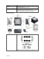
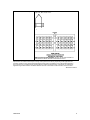
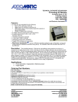
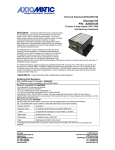
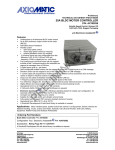
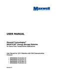
Technical Datasheet #TDAXTC20 Thermocouple Scanner 20 Thermocouple Channels CAN, SAE J1939 with Electronic Assistant® P/N: AXTC20 Description: The Thermocouple Scanner monitors up to 20 thermocouples and provides the temperature information to the engine control system over SAE J1939 CAN bus. The channels are independently configurable as Type J, K, B, E, N, R, S or T thermocouples. Temperature information can include exhaust temperature, winding temperature, and fluid temperature monitoring. All 20 channels of temperature data are automatically sent over the CAN bus when power is applied with no additional programming or configuration required. Integral diagnostics determine thermocouple integrity. All channels are fully isolated from the CAN line, and from the power supply. During set-up, using an USB-CAN converter and a PC, the operator can configure the controller via the Axiomatic Electronic Assistant® to suit a wide variety of applications. Settings are saved to non-volatile memory upon command. A CANopen® model is available. The Thermocouple Scanner features rugged packaging and watertight Deutsch IPD connectors for an IP65 rating. The module is UL recognized for UL508 (FTPM2) – Controls for Stationary Engine Driven Assemblies and has a cUL recognition as well. The control carries a CE mark for the EMC and RoHS Directives. The AXTC20 meets the environmental, EMC and vibration requirements of generator set applications in marine installations and has type approvals from several marine societies (LR, DNV, ABS, etc.). Applications: Control systems for industrial and marine power generator sets (stationary or portable) Ordering Part Numbers: 20 Channel Thermocouple Module, SAE J1939 P/N: AXTC20 A CANopen® model is available under ordering p/n: AXTC20CO. Electronic Assistant Service Tool P/N: AX070502 This Kit includes the following items. USB-CAN Converter P/N: AX070501 1 ft. (0.3 m) USB Cable P/N: CBL-USB-AB-MM-1.5 12 in. (30 cm) CAN Cable with female DB-9 P/N: CAB-AX070501 AX070502IN CD P/N: CD-AX070502, includes: Electronic Assistant® software; EA & USB-CAN User Manual UMAX07050X; USB-CAN drivers & documentation; CAN Assistant (Scope and Visual) software & documentation; and the SDK Software Development Kit. Mating Plug Kit P/N: AX070200 This kit includes the following items. These items are also available from a local Deutsch IPD distributor. NB. The sealing plugs are only needed in cases where less than 20 thermocouple channels are installed. A crimping tool from Deutsch IPD is required to connect wiring to the sockets, P/N: HDT 48-00 or equivalent (not supplied). Deutsch IPD P/N: Description: 0462-201-16141 48 16AWG SOCKETS SOLID 16-20AWG WIRE 6mm 114017 24 SEALING PLUGS SIZE 12-16 CAVITIES 12-18 AWG DRC16-40S 40-PIN PLUG, No Key DT06-08SA DT SERIES PLUG 8 CONTACT W8S WEDGELOCK FOR DT 8 PIN PLUG Axiomatic Technologies Corporation 5915 Wallace Street, Mississauga, Ontario Canada L4Z 1Z8 TEL: (905) 602-9270 FAX: (905) 602-9279 E-mail: [email protected] www.axiomatic.com Block Diagram TDAXTC20 2 Technical Specifications Inputs Power Supply Input Supply Current Protection Thermocouple Types Thermocouple Inputs 12V or 24VDC nominal (9…32 VDC power supply range) 200 mA at 12 V Typical 100 mA at 24 V Typical Reverse polarity protection is provided. Power supply input section protects against transient surges and short circuits and is isolated from thermocouple inputs Up to 20 channels, independently configurable for B, E, J, K, N, R, S or T The device reads mV signals from the supported Thermocouples. B = 0 to 13.82 mV E = -9.835 to 76.373 mV J = -8.095 to 69.553 mV K = -6.458 to 54.886 mV N = -4.345 to 47.513 mV R = -0.226 to 21.101 mV S = -0.236 to 18.693 mV T = -6.258 to 20.872 mV Temperatures are configured to indicate the SAE J1939 SPN to be transmitted by that temperature input. Scan Rate Common Mode Readings Thermal Drift Isolation SPNs and PGNs Accuracy: +/- 1°C typical with cold junction compensation at ambient temperature Resolution: 0.001°C 100ms per channel, total sweep time maximum 2.2 seconds Input range +/- 4V maximum Rejection is 100db at 5Vp-p (50-60Hz) 150 ppm/°C of span (maximum) Digital isolation is 500VDC from input to ground. Three way isolation is provided for the CAN line, inputs and power supply The SPN drop list includes all temperature SPNs from the J1939-71 standard published up to January of 2009. If an SPN is not supported by the drop list, the user can select a zero SPN, which then allows them to define the SPN and PGN per the application requirements. One byte parameters have a resolution of 1 C / bit and a range of -40 C to 210 C. Two byte parameters have resolution of 0.03125 C / bit and a range of -273 C to 1735 C (per SAE J1939). Averaging Protection The Parameter Group Number (PGN) that will be used to send a temperature to the J1939 network will be entirely dependent on the Suspect Parameter Number (SPN) that was selected for that channel. In all cases, the PGN is a PDU2 type. Each PGN has a predefined priority and repetition rate associate with it. The average temperature of all the active channels can be broadcasted to the network using the default “Engine Average Information” PGN, or on a Proprietary B message. Open circuit detection Frozen data detection Over or under temperature detection High temperature shutdown detection Communication CAN Network Termination RS-232 TDAXTC20 1 CAN 2.0B port, protocol SAE J1939 Digital isolation is provided for the CAN line. According to the CAN standard, it is necessary to terminate the network with external termination resistors. The resistors are 120 Ohm, 0.25W minimum, metal film or similar type. They should be placed between CAN_H and CAN_L terminals at both ends of the network. 1 RS-232 port is available for debugging purposes. ASCII Text Format, 115200 Baud Rate Data – 8 bit, Parity – None, Stop – 1 bit. Flow Control – Xon/Xoff. Short circuit protection to ground. 3 General Specifications Microprocessor Control Logic SAE J1939 Profile Diagnostics MC56F8366,16-bit, 512 kByte flash program memory User programmable functionality with the Electronic Assistant® Node address is auto configurable as per J1939-81 and/or via customer configuration. Monitored parameters and diagnostics are user selectable from a drop down list in the EA. Monitored parameters and diagnostics are read-only over the network Units are pre-configured with default values at the factory. Refer to the user manual. The bit-rate is 250 kbit/s. Other bit-rates (125 kbit/s, 500 kbit/s or 1 Mbit/s) can be factory programmed on request. Contact Axiomatic for an ordering p/n. All parameter locations have default values that do not conflict. Module is fully functional during configuration and communications. Parameter values and diagnostic error codes are retained when the modules are de-energized. Easily selectable SPNs from a drop down list of the temperature SPNs supported by SAE J1939. User defined SPN and PGN’s configurable with Electronic Assistant® to suit the application. Configurable ECU Instance in the NAME to allow for multiple ECU’s on the same network For J1939 compliance (SAE, Recommended Practice for a Serial Control and Communications Vehicle Network, October 2007) all modules comply with the applicable portions of the following: SAE J1939-21, December 2006, Data Link Layer SAE J1939-71, January 2009, Vehicle Application Layer SAE J1939-73, September 2006, Application Layer – Diagnostics SAE J1939-81, May 2003, Network Management Customer specific proprietary extensions can also be included in the SAE J1939 profile on request. Configurable Diagnostic Messaging parameters Diagnostic Log is maintained in non-volatile memory. Each thermocouple channel could be configured to send diagnostic messages to the network if the temperature goes out of range. User Interface UL and cUL Compliance CSA Approval ATEX Compliance CE Compliance Vibration Marine Type Approval Operating Temperature Range Storage Temperature Range TDAXTC20 When sending an “Active Diagnostic Trouble Code” (DM1) or a “Previously Active Diagnostic Trouble Codes” (DM2) message, the controller will use the appropriate Diagnostic Trouble Code (DTC). As defined by the standard, this is a combination of the Suspect Parameter Number (SPN), the Failure Mode Indicator (FMI), Occurrence Count (OC) and the SPN Conversion Method (CM). Electronic Assistant®, P/N: AX070502 Updates for the EA are found on www.axiomatic.com under the log-in tab. UL508 (April 2010) (FTPM2) – Controls for Stationary Engine Driven Assemblies cUL C22.2 No. 14-10 (2010) Class I, Division 2, Groups A, B, C, D T4 Ex nA IIC T4 Gc Unit must be mounted in an explosion proof enclosure. ATEX Certificate: Sira 15ATEX4138X II 3G Ex nA IIC T4 Gc Compliance to: EN60079-0:2012/A2013 and EN60079-15:2010 Unit must be mounted in an explosion proof enclosure. 2004/108/EC (EMC Directive) 2011/65/EU (RoHS Directive) 8 G for a rail mounted and vibration isolated device The marine type approval process tested to 4.0 G per IEC 60068-2-6, Test Fc. Lloyd’s Register, DNV, ABS, RINA, GL, BV, CCS, IRS, RS The AXTC20 meets the environmental, EMC and vibration requirements of generator set applications in marine installations. -40 to 85 ºC (-40 to 185 ºF) -50 to 120 ºC (-58 to 248 ºF) 4 Humidity Protection Weight Enclosure Protected against 95% humidity non-condensing, 30 ºC to 60 ºC IP67 Pollution Degree 3 per UL508 The marine type approval process tested to IP56. 2.2 lbs. (1.00 kg) Rugged aluminum housing, stainless steel end plates, neoprene gaskets 145.30 x 149.00 x 73.00 mm (5.72 x 5.86 x 2.87”) L x W x H Connectors, Deutsch IPD P/N: 1 8-pin DT13-08PA, 1 40-pin DRC13-40PA It can be mounted directly on the power generator set or remotely. Dimensional Drawing Electrical Pin Out – Power and CAN TDAXTC20 5 Electrical Pin Out - Thermocouples Type J, K, B, E, N, R, S or T + - Mating Connector Part Number: Deutsch IPD p/n DRC16-40SE-A or DRC18-40SA or DRC16-40S with sockets 0462-201-16141 Specifications are indicative and subject to change. Actual performance will vary depending on the application and operating conditions. Users should satisfy themselves that the product is suitable for use in the intended application. All our products carry a limited warranty against defects in material and workmanship. Please refer to our Warranty, Application Approvals/Limitations and Return Materials Process as described on www.axiomatic.com/service.html. TDAXTC20-10/22/15 TDAXTC20 6