Transcript
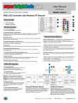
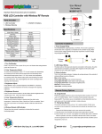
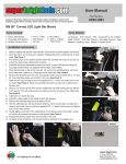
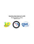
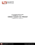
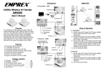
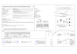
User Manual
Part Number:
MCBRF-RGB-5ALC4
WIFI-CON
Important: Read all instructions prior to installation.
RGB LED Controller with Wireless RF Remote
Model
Dynamic Mode
Static Color
PWM Grade
Brightness Grade
Speed Grade
Overload Protection
Overheat Protection
Working Voltage
Battery
Remote Frequency
Remote Distance
Working Temperature
Rated Output Current
PWM Frequency
IP Rating
FCC ID
Parts Included
1 - LED Controller
1 - Wireless Remote
1 - CR2025 3V Battery
Wireless Remote Functions
1. Turn On(|) / Standby(O)
Press ‘I’ key to turn on unit or press ‘O’ key to turn off. Retains last setting between
power off and power on.
2. Mode(+)/Mode(-) Dynamic Modes
Dynamic modes feature a variety of static color transitions and patterns, with 43 distinct modes.
These buttons initiate Dynamic Mode and cycle through the modes in ascending(+) or descending(-)
order.
4
6
5
7
8
12
11
1. Disconnect the power to the LED controller, wait 5 seconds, and reconnect.
2. Within 5 seconds of reconnecting the LED Controller, press the “Mode(-)”
and “Speed(-)” buttons simultaneously.
9 indicator on the LED controller will flash white 3 times indicating the
3. The LED
new wireless remote has been successfully assigned. This may be done for a
total of 3 wireless remotes.
3
7. Increase(+)/Decrease(-) Static Color Brightness Level
Increases(+) or decreases(-) the brightness of the currently active static color.
2 Initiates Static Color
Mode if Dynamic Mode is currently active.
Pairing Any Remote: Up to 3 wireless remotes can be assigned to operate the
4 The following steps show how to assign a new remote to the
LED controller.
LED Controller:
5
8. Direct Color Select
6 are also accessible
Activates the static color indicated by the button color. These individual colors
through the Color(+)/Color(-) Static Colors buttons.
1. Disconnect the power to the LED controller, wait 5 seconds, and reconnect.
7
2. Within 5 seconds of reconnecting the LED Controller, press the “On(I)” and
“Play/Pause (
=)” buttons simultaneously.
3. The LED indicator on the LED controller will flash yellow 3 times indicating
8
the LED controller will recognize any remote.
9. Wireless Remote LED Indicator
Flashes blue when remote is operating to indicate that remote is functioning properly.
12. LED Controller Status Indicator
A multi-color emitting LED located on the remote
controller indicates current operating status or
operating status changes as follows:
2
Power
6. Color(+)/Color(-) Static Colors
Initiates static Color Mode and cycle through the colors in ascending(+) or descending(-)
order.
1
Black(V+): Common anode which connects as the
positive (line) connection inside the controller.
Red(R): Wire connection for red LED color signals.
Green(G): Wire connection for green LED color signals.
Blue(B): Wire connection for blue LED color signals.
3
Supply Up to 3 wireless remotes can be assigned to operate
Pairing A New Remote:
the LED controller. Additionally, each individual wireless remote can be
assigned to an unlimited number of controllers. The following steps show how
to assign a new remote to the LED Controller:
5. Demo Mode
Initiates Demo Mode. Demo Mode cycles through 43 individual modes, repeating each mode 3 times.
11. LED Output Wiring (LC4 Connector)
The controller supports common anode-type LED RGB
strips. Output wires are indicated as follows:
1
10 13
4. Speed(+)/Speed(-) Speed Level
Increases(+) or decreases(-) the tempo of the currently active dynamic mode. Initiates Dynamic Mode if
Static Color Mode is currently active.
10. Power Supply Wiring
The controller/power supply operates at 5-24VDC. The
red wire is positive(+) and the black wire is negative(-)
as indicated on the controller housing. Make sure the
power voltage matches the LED strip requirement.
Incorrect voltage may damage the LED strip.
9
Remote Pairing
Options
To
3. Play ( =) / Pause
Toggles between run/pause when in Dynamic Mode or Demo Mode. Initiates Dynamic Mode if Static
Color Mode is currently active.
Controller Installation
MCBRF-RGB-5ALC4
43 Modes
30 Colors
256 Levels
5 Levels
10 Levels
Yes
Yes
DC 5-24V
3V CR2025
433.92MHz
Up to 15 Meters (Open Area)
-30° to 80° C
3 x 5.0A
1 KHz
IP68
2ACJPRM03
10 12
FCC Statement
11
This device complies with part 15 of the FCC Rules. Operation
is subject to the following two conditions: (1) This device may
not cause harmful interference, and (2) This device must accept
any interference received, including interference that may cause
undesired operation. Any changes or modifications in construction
of this device which are not expressly approved by the party
responsible for compliance could void the user’s authority to
operate the equipment.
To
Power
Supply
To
LED Strip
RGB LED Controller Status Indicator
Light Signal
Indicates
Blue
normal
function
Short single
white flash
Long single
white flash
mode change
Range limit has
been reached
when cycling
through Dynamic
or Static color
modes
Using the Wireless Remote
Prepare the wireless remote for use by removing the battery
insulator. The remote uses a 3V CR2025 battery. Note:
The wireless remote operates using radio frequency(RF).
The remote controller’s use is not restricted by normal
obstructions such as walls, doors, etc. Do not install
controller in metal enclosures.
Long single
yellow flash
Blue flash
Red flash
Range limit has
Overload/short
been reached
circuit has
when cycling
Dynamic mode is been detected,
through Tempo
paused
activating
Speed Level
protection mode
or Static color
Brightness Level
Yellow flash
Overheating has
been detected,
activating
protection mode
Additional Features
Waterproof LED Controller - The MCBRF-RGB-5ALC4 LED
controller is fully waterproof according to the IP68 standard
and can be installed and operated underwater up to a depth of
30 meters. Note: LED controller sensitivity to wireless remote
signals will decrease when operated in underwater conditions.
Make sure to perform all wiring connections and setup prior to
installing LED controller underwater.
4400 Earth City Expy, St. Louis, MO 63045 866-590-3533
superbrightleds.com