1
KGCoE MSD
Technical Review Agenda
Azamat Boranbayev
Nick Liotta
Mike Miranda
Sigitas Rimkus
Alex Usachev
P11543: Variable LED Hemispherical Imager
Meeting Purpose: Detailed design review of P11543 – Variable LED Hemispherical Imager. The objectives of this are to present and receive feedback from others about our final design and bill of materials.
Meeting Date: February 9, 2011
Meeting Location: 78-2150
Meeting Time: 3:00 - 5:00 PM
1
Project #
11543
Start Term
20102
1
Project Name
Variable LED Hemispherical Imager
Team Guide
Prof. Hanzlik
Project Track
Printing and Imaging
Systems
Project Sponsor
Dr. Wyble and Dr. Gu
Project Description
1.1
Project Background
1.2
Objectives and Scope
Project Family
N/A
Doc. Rev.
1.1
• Control system operating 14 LEDs independently for intensity and on-off time.
• Provide user friendly PC window type interface.
The many forms of LEDs are the emerging technol• Work with mechanical team to provide a harogy for illumination. Fundamental evaluation and
nessing solution from the hemisphere to the
quantification of image appearance as a function of
control electronics and the PC.
illumination spectrum, intensity, and incident angles
require a tunable light source. An illumination cav• Conduct testing of electrical subsystems.
ity consisting of a 1 meter diameter hemisphere is
required. The design of the hemisphere will enable Mechanical Engineering
repeatable positioning of LED clusters. The hemi• Design and development of a 1-meter hemisphere will be broken into 5 degree increments for
sphere that can mount and locate the LED clusboth latitude and longitude. The LED cluster will
ters.
consist of 1-7 LEDs mounted in a repeatable manner
to maximize additivity of output. Customer required
• Development, design, and delivery of a cluster
at least two (2) LED clusters to be operational at
module that holds LEDs in the required geoany point in time. Additionally, each of the seven
metrical relationship and enables easy moveLEDs within the cluster should be addressable for
ment to other positions of the cluster within
intensity and on-off time control. This means up to
the hemisphere.
14 independent addressable LED outputs. Customer
• Development, design, and delivery of reliable
interface should be some user friendly PC window for
electrical connections and quick disconnect and
initial setup and running.
removal.
1.4
This project consists of three main objectives:
• Azamat Boranbayev (ME)
• Design a hemisphere containing mounting
points for multiple LED clusters.
• Nick Liotta (EE)
• Mike Miranda (EE)
• Design clusters of LEDs in order to project light
in the visible spectrum, as well as in the IR and
UV spectrums.
• Sigitas Rimkus (ME)
• Alex Usachev (CE)
• Design a computer-based control system in order to selectively address each LED within a
particular cluster.
1.3
Core Team Members
2
Document Outline
This report contains the following items and documents in the order listed below.
Deliverables
A fully functional 1-meter hemispherical LED based
illumination system with user manual and all supporting documentation.
• Customer Needs
• Engineering Specifications
Deliverables by Discipline
• Project Timeline
Electrical and Computer Engineering
• Risk Assessment
1.3.1
2
3.2
• LED Cluster Assembly
– LED Cluster
– PCB Housing
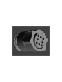
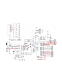
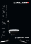
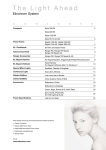
The microcontroller being used in the Arduino Duelminelove. It interfaces with MATLAB to control
each LED in the cluster with an 8-bit output allowing the user to alter the intensity of a desired LED as
needed. There is one microcontroller used per cluster, providing 6 PWM outputs and one digital output
to each cluster. The microcontrollers are stored in
a ”black-box” which will house communication and
power cables, as well as provide easy access to each
microcontroller if the need for troubleshooting arises.
• LED Control
• Hemisphere
3
3.1
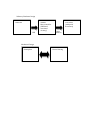
LED Control
Component Overview
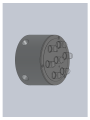
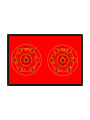
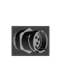
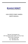
LED Cluster Assembly
The LED cluster will be constructed in order to provide a PCB mounting point for all the LEDs on top
of a cylindrical shell which will interface with the
geodesic hemisphere. The LEDs will be user replaceable through PCB through-hole connectors and all
wire strain relief will be provided by the internal geometry of the cluster housing. All control signal wires
will be routed through the housing out to a CPC connector. Cable will be used to provide an interface
between the LED control mechanism and the LED
cluster.
3.3
Hemisphere
The hemisphere is the interface point for the LED
cluster assembly. It is used to direct light from the
LED cluster onto a designated sample area from various locations. The LED cluster is attached to the
hemisphere through the use of magnets embedded
into the based of each cluster.
3
!"#$%&'()*&'+%&'(,-(./01,
,
,
,
267869,,
,
,
C!9,,
6'+:/1",
2/3'"3"1$'"55(',
;<=2,&1+,
&.."3/&$(+,
3/'3:/$'>?,
,
,
,
8(+,@5:.$(',
;%/$4,A:/3B,
+/.3"11(3$?, ,
,@&D5(,
*&'1(..,
,
,
,
,
,
,
2(34&1/3&5,-(./01,
*(E/.F4('(, ,
,
,
@5:.$(',*":./10,
3
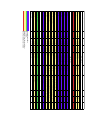
CN1
CN2
CN3
CN4
CN5
5
5
5
2
5
4
3
4
5
3
3
3
1
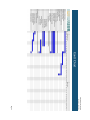
Importance
CN6
CN7
CN8
CN9
CN10
CN11
CN12
CN13
5
5
4
2
Revision #
Customer
Need #
CN14
CN15
CN16
CN17
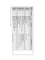
Description
LED Controls
Control individual intensities of LEDs
8-bit control
Serial commands for each LED
MATLAB software interface
No power constraints
LED Cluster
At least 2 clusters of 7 LEDs
Individually addressable LEDs
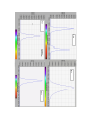
Cover entire visible light (possibly UV and IR as well)
Cluster housing
LED cluster must illuminate sample area
Individually replaceable LEDs
Quick, reliable disconnect
Cluster uniformly illuminates target area
Hemisphere
Dome geometry needs to be a hemisphere
Repeatable alignment of cluster mounting locations
Mounting locations identified and labeled
Minimal weight
Importance: Scale of 1-5 (1 = preference only, 5 = must have)
PWM
Comments/Status
Does not want GUI
Possibility of expansion
Adjustable brightness
Visible spectrum more important
Minimize potential damage to electronics
Avoid need of having to replace entire cluster
Ensure system portability
9
10
11
12
13
14
15
1
2
3
4
5
6
7
8
5
4
3
3
1
5
5
3
3
3
2
4
5
5
5
5
4
4
4
4
Importance
CN14
CN15/CN16
CN15/CN16
CN17
CN2
CN5
CN4
CN4
CN5
CN8
CN10
CN9
CN13
CN6
CN12
CN13
CN7
CN1/CN3
CN6
CN11
CN11
CN10
CN10
CN10
Customer
Need #
3
16
17
18
19
20
5
5
4
1
Revision #
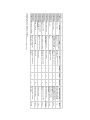
Engineering
Spec #
21
22
23
24
Specification (description)
LED
Individual addressability
Individual intensity control
Amount per cluster
Individual disconnect time
Individual replaceability
Cone angle
Casing
Individual drive current
LED Cluster
Spectral range covered
Illumination of sample area
Casing
Casing diameter
Amount
Disconnect time
Uniform illumination
Microprocessor
Separate PWM output for each LED
Input voltage
USB connection
MATLAB compatibility
Power constraints
Hemisphere
Diameter
Measurable location of each node
Number of cluster mounting locations
Weight
Unit of
Measure
Binary
bit
#
sec
Binary
deg
mm
mA
nm
Binary
Binary
cm
#
sec
Binary
Binary
V
Binary
Binary
Binary
m
Binary
#
kg
Yes
8
7
Marginal Value
Ideal Value
15-20
Yes
7 - 12
Yes
Yes
No
400-650
Yes
Yes
<5.1
>2
<30
Yes
Yes
8
7
<30
Yes
<18
5
20
15-25
415-690
2
Yes
6 - 20
Yes
Yes
1
Yes
324
<14
Using pulse-width modulation
Comments/Status
If using UV or IR cluster, 6 can be used since 7th output will be digital
T1-3/4
Gaps may appear, especially within the green spectrum
Methods still in debate
Center LED will be digital, most likely to be white
Arduino microprocessor comes with USB port
No GUI
~10 degree separation of nodes for longitude and latitude
Light enough to be hand portable
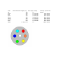
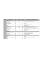
Color
UV
Violet
Blue
Aqua
Green
Yellow
Orange
Red
White
Dominant Wave Length (nm) Cone Angle Range
380
15
420
15 415-490
467
15 420-490
505
18 480-540
525
20 490-570
590
15 575-610
605
15 570-640
644
15 630-690
x=.29 y=.29
15
Intensity (mcd)
Current
30mW
1000 20mA
5500 20mA
9000 20mA
8000 20mA
5600 20mA
5000 20mA
5000 20mA
18000 20mA
Violet
($)%'
!"#$%&'
*+),'
-.%%/'
!"##$%&
'()*+"&
,"-&
./01"&
35235,(7$5<$1'&21),'(17,$/
7+(,1)250$7,21&217$,1(',17+,6
'5$:,1*,67+(62/(3523(57<2)
,16(57&203$1<1$0(+(5(!$1<
5(352'8&7,21,13$5725$6$:+2/(
:,7+2877+(:5,77(13(50,66,212)
,16(57&203$1<1$0(+(5(!,6
352+,%,7('
1(;7$66<
$33/,&$7,21
86('21
&200(176
4$
0)*$335
(1*$335
&+(&.('
'5$:1
7$33('
81/(6627+(5:,6(63(&,),('
',0(16,216$5(,1,1&+(6
72/(5$1&(6
)5$&7,21$/
$1*8/$50$&+ %(1'
7:23/$&('(&,0$/
7+5((3/$&('(&,0$/
,17(535(7*(20(75,&
72/(5$1&,1*3(5
1RQH
$OXPLQXP
0$7(5,$/
),1,6+
'21276&$/('5$:,1*
1$0(
'$7(
6&$/( :(,*+7
5(9
6+((72)
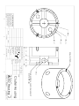
$/('B+RXVLQJ 6,=( ':*12
&OXVWHU+RXVLQJ
7,7/(
02817,1*+2/()250$*1(7
'((3[
6-5
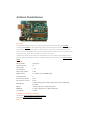
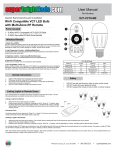
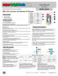
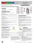
Arduino Duemilanove
Overview
The Arduino Duemilanove ("2009") is a microcontroller board based on the ATmega168 (datasheet)
or ATmega328(datasheet). It has 14 digital input/output pins (of which 6 can be used as PWM outputs), 6
analog inputs, a 16 MHz crystal oscillator, a USB connection, a power jack, an ICSP header, and a reset
button. It contains everything needed to support the microcontroller; simply connect it to a computer with a
USB cable or power it with a AC-to-DC adapter or battery to get started.
"Duemilanove" means 2009 in Italian and is named after the year of its release. The Duemilanove is the
latest in a series of USB Arduino boards; for a comparison with previous versions, see the index of Arduino
boards.
Summary
Microcontroller
ATmega168
Operating Voltage
5V
Input Voltage
(recommended)
7-12V
Input Voltage (limits)
6-20V
Digital I/O Pins
14 (of which 6 provide PWM output)
Analog Input Pins
6
DC Current per I/O Pin
40 mA
DC Current for 3.3V Pin
50 mA
Flash Memory
16 KB (ATmega168) or 32 KB (ATmega328) of which 2 KB used by
bootloader
SRAM
1 KB (ATmega168) or 2 KB (ATmega328)
EEPROM
512 bytes (ATmega168) or 1 KB (ATmega328)
Clock Speed
16 MHz
Schematic & Reference Design
EAGLE files: arduino-duemilanove-reference-design.zip
Schematic: arduino-duemilanove-schematic.pdf
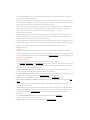
Power
The Arduino Duemilanove can be powered via the USB connection or with an external power supply. The
power source is selected automatically.
External (non-USB) power can come either from an AC-to-DC adapter (wall-wart) or battery. The adapter
can be connected by plugging a 2.1mm center-positive plug into the board's power jack. Leads from a battery
can be inserted in the Gnd and Vin pin headers of the POWER connector.
The board can operate on an external supply of 6 to 20 volts. If supplied with less than 7V, however, the 5V
pin may supply less than five volts and the board may be unstable. If using more than 12V, the voltage
regulator may overheat and damage the board. The recommended range is 7 to 12 volts.
The power pins are as follows:
•
VIN. The input voltage to the Arduino board when it's using an external power source (as opposed to 5 volts
from the USB connection or other regulated power source). You can supply voltage through this pin, or, if
supplying voltage via the power jack, access it through this pin.
•
5V. The regulated power supply used to power the microcontroller and other components on the board. This
can come either from VIN via an on-board regulator, or be supplied by USB or another regulated 5V supply.
•
3V3. A 3.3 volt supply generated by the on-board FTDI chip. Maximum current draw is 50 mA.
•
GND. Ground pins.
Memory
The ATmega168 has 16 KB of flash memory for storing code (of which 2 KB is used for the bootloader);
the ATmega328 has 32 KB, (also with 2 KB used for the bootloader). The ATmega168 has 1 KB of SRAM and
512 bytes of EEPROM (which can be read and written with the EEPROM library); the ATmega328 has 2 KB
of SRAM and 1 KB of EEPROM.
Input and Output
Each of the 14 digital pins on the Duemilanove can be used as an input or output,
using pinMode(), digitalWrite(), anddigitalRead() functions. They operate at 5 volts. Each pin can provide or
receive a maximum of 40 mA and has an internal pull-up resistor (disconnected by default) of 20-50 kOhms.
In addition, some pins have specialized functions:
•
Serial: 0 (RX) and 1 (TX). Used to receive (RX) and transmit (TX) TTL serial data. These pins are
connected to the corresponding pins of the FTDI USB-to-TTL Serial chip.
•
External Interrupts: 2 and 3. These pins can be configured to trigger an interrupt on a low value, a rising
or falling edge, or a change in value. See the attachInterrupt() function for details.
•
•
PWM: 3, 5, 6, 9, 10, and 11. Provide 8-bit PWM output with the analogWrite() function.
SPI: 10 (SS), 11 (MOSI), 12 (MISO), 13 (SCK). These pins support SPI communication using the SPI
library.
•
LED: 13. There is a built-in LED connected to digital pin 13. When the pin is HIGH value, the LED is on,
when the pin is LOW, it's off.
The Duemilanove has 6 analog inputs, each of which provide 10 bits of resolution (i.e. 1024 different values).
By default they measure from ground to 5 volts, though is it possible to change the upper end of their range
using the AREF pin and the analogReference() function. Additionally, some pins have specialized
functionality:
•
I2C: 4 (SDA) and 5 (SCL). Support I2C (TWI) communication using the Wire library.
There are a couple of other pins on the board:
•
AREF. Reference voltage for the analog inputs. Used with analogReference().
/public/
P11543: Variable LED Hemispherical Imager
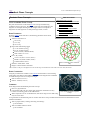
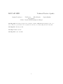
Geodesic Dome Concepts
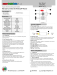
Geodesic Dome Concepts
2V/L2 Icosahedral Dome Concept
The plans for this dome can be found here. The concept was built using
toothpicks and a hot glue gun. The length of each strut was normalized to the
length of one toothpick, meaning that the longest strut was a toothpick in
length, the second longest was a certain percentage of that, et cetera.
Dome Parameters
From the website mentioned above, the following parameters for the dome
were found:
Vertices/connections: 26
10 x 4-way
6 x 5-way
10 x 6-way
Table of Contents
1 Geodesic Dome Concepts
1.1 2V/L2 Icosahedral Dome Concept
1.1.1 Dome Parameters
1.1.2 Dome Construction
1.1.3 Comments
1.2 3V Octahedral Dome Concept
1.2.1 Dome Parameters
1.2.2 Dome Construction
1.2.3 Comments
2 General Comments on Dome Concepts
Edges/struts and bending angles
A x 30: 0.54653 (15.86 o )
B x 35: 0.61803 (18.00 o )
Total: 65 struts (2 different kinds)
Strut variance of 13.1%1
Faces: 40 (3-sided)
A-A-A x 30 (55.57 o , 55.57 o , 68.86 o )
B-B-B x 10 (60.00 o , 60.00 o , 60.00 o )
2 different kinds of faces
Diameter: 2.000, radius: 1.000
Height: 1.000 or 50.00% of diameter
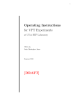
2V/L2 Icosahedral Dome Construction
Map
1 The variance is the percent difference between the longest and shortest struts. The lower the value, the better.
Dome Construction
Using the provided dome calculator at the website mentioned above, the following
strut lengths were obtained. It should be noted that the strut lengths were normalized
such that the longest strut is a toothpick in length.
Strut A: 0.8843 (2-3/16 in.)
Strut B : 1.0000 (2-9/16 in.)
Comments
Some things learned from building this dome concept:
Has a very rigid structure.
If expanded to full scale, the various strut orientations would allow for easy
location of mounting points for the LED clusters.
When compared to the 3V octahedral dome, this dome is larger in size while using
only five more struts.
2V/L2 Icosahedral Dome Completed
Concept
A rough estimate of manufacturing time to construct this dome concept would be between 80 and 105 minutes based on the
estimates listed below.
Time to prepare struts (counting, measuring, and cutting):
20-30 minutes
Time to assemble struts into dome:
60-75 minutes
Total time required:
80-105 minutes
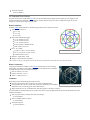
3V Octahedral Dome Concept
The plans for this dome can be found here. The concept was built using toothpicks and a hot glue gun. The length of each
strut was normalized to the length of one toothpick, meaning that the longest strut was a toothpick in length, the second
longest was a certain percentage of that, et cetera.
Dome Parameters
From the website mentioned above, the following parameters for the dome were found:
Vertices/connections: 25
4 x 3-way
9 x 4-way
12 x 6-way
Edges/struts and bending angles
A x 16: 0.45951 (13.28 o )
B x 20: 0.63246 (18.44 o )
C x 24: 0.67142 (19.62 o )
Total: 60 struts (3 different kinds)
Strut variance of 46.1%1
Faces: 36 (3-sided)
A-A-B x 12 (46.51 o , 46.51 o , 89.98 o )
B-C-C x 24 (56.20 o , 61.90 o , 61.90 o )
2 different kinds of faces
3V Octahedral Dome Construction Map
Diameter: 2.000, radius: 1.000
Height: 1.000 or 50.00% of diameter
1 The variance is the percent difference between the longest and shortest struts. The lower the value, the better.
Dome Construction
Using the provided dome calculator at the website mentioned above, the following
strut lengths were obtained. It should be noted that the strut lengths were normalized
such that the longest strut is a toothpick in length.
Strut A: 0.6844 (1-12/16 in.)
Strut B : 0.9420 (2-7/16 in.)
Strut C: 1.0000 (2-9/16 in.)
Comments
Some things learned from building this dome concept:
Has a less rigid structure when compare to the 2V/L2 icosahedral dome.
3V Octahedral Dome Completed Concept
If expanded to full scale, the various strut orientations would allow for somewhat
difficult location of mounting points for the LED clusters.
When compared to the 3V octahedral dome, this dome appears to be far less "elegant".
A rough estimate of manufacturing time to construct this dome concept would be between 100 and 120 minutes based on the
estimates listed below.
Time to prepare struts (counting, measuring, and cutting):
30-40 minutes
Time to assemble struts into dome:
70-80 minutes
Total time required:
100-120 minutes
35235,(7$5<$1'&21),'(17,$/
1(;7$66<
$33/,&$7,21
PP
7+(,1)250$7,21&217$,1(',17+,6
'5$:,1*,67+(62/(3523(57<2)
,16(57&203$1<1$0(+(5(!$1<
5(352'8&7,21,13$5725$6$:+2/(
:,7+2877+(:5,77(13(50,66,212)
,16(57&203$1<1$0(+(5(!,6
352+,%,7('
6WHHO
1RQH
&200(176
4$
0)*$335
(1*$335
&+(&.('
'5$:1
&/($5$1&(
+2/([
81/(6627+(5:,6(63(&,),('
),1,6+
0$7(5,$/
,17(535(7*(20(75,&
72/(5$1&,1*3(5
',0(16,216$5(,1,1&+(6
72/(5$1&(6
)5$&7,21$/
$1*8/$50$&+ %(1'
7:23/$&('(&,0$/
7+5((3/$&('(&,0$/
86('21
'21276&$/('5$:,1*
6-5
1$0(
'$7(
7,7/(
6+((72)
5(9
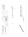
6WUXW7\SH$
$B6WUXW
6,=( ':*12
$
6&$/( :(,*+7
35235,(7$5<$1'&21),'(17,$/
1(;7$66<
PP
7+(,1)250$7,21&217$,1(',17+,6
'5$:,1*,67+(62/(3523(57<2)
,16(57&203$1<1$0(+(5(!$1<
5(352'8&7,21,13$5725$6$:+2/(
:,7+2877+(:5,77(13(50,66,212)
,16(57&203$1<1$0(+(5(!,6
352+,%,7('
$33/,&$7,21
),1,6+
&200(176
4$
0)*$335
(1*$335
&+(&.('
'5$:1
&/($5$1&(
+2/([
1RQH
6WHHO
0$7(5,$/
,17(535(7*(20(75,&
72/(5$1&,1*3(5
',0(16,216$5(,1,1&+(6
72/(5$1&(6
)5$&7,21$/
$1*8/$50$&+ %(1'
7:23/$&('(&,0$/
7+5((3/$&('(&,0$/
81/(6627+(5:,6(63(&,),('
86('21
'21276&$/('5$:,1*
6-5
1$0(
'$7(
7,7/(
6+((72)
5(9
6WUXW7\SH%
%B6WUXW
6,=( ':*12
$
6&$/( :(,*+7
8#
+
3
2
1
Nodes not being accurate
>75 mA LEDs
More than 2 clusters
Possibility of sphere
Redesign control circuit or black
Poor engineering
box
Need multiple microcontrollers
Cluster location unknown to
computer software
Budget
More than two clusters required
by customer
Poor manufacturing
Need to cover required
spectrum
Additional requirements from the
customer
Customer changes need (should
know by 12/17)
Cause
2
1
2
2
3
2
3
Likelihood
9
9
1
3
9
1
3
3
Severity
9
18
1
6
18
3
6
9
Importance
Confirm equipment availability
with customer
Simulate with prototype
Build a good prototype
Find a device with enough PWM
outputs.
Jig hemisphere accurately
Talk with customer and decide
on action as soon as possible
Action to Minimize Risk
Miranda
Usachev
Liotta
ALL
Owner
2
Risk Item
4
Not having enough PWM
outputs
Bugs in code
1
Revision #
ID
5
Need more components to
interface cluster with
microcontroller
Cannot control PWM
Unavailability of needed testing
equipment
Usachev
Rimkus,
Boranbayev
Miranda
Usachev
6
MATLAB functionality
Unable to characterize LEDs
and spectrum covered
Effect
Need to make two hemispheres
that are easily connected
together
Need larger microcontroller,
more LEDs, more housings, et
cetera
7
Testing equipment availability
Be able to build more clusters
and use a larger microcontroller
than needed
Understand what spectrum
range can be covered. Request
larger budget
8
Likelihood: Scale of 1-3 (1 = unlikely, 3 = very likely)
Severity: Scale of 1,3,9 (1 = not severe, 3 = somewhat severe, 9 = critically severe)
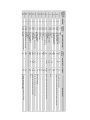
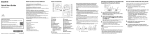
PN
.125"x.5"x6' Steel
Notes
None
Lead Tme
Item Total Ordered Vendor
8910K113
Unit Cost
Hemisphere
$89.32 McMastercarr
Qty
$6.38
Description
14
Neodymium-iron-boron
Struts
92865A540
93827A211
5902K48
Need 4 More
AC/DC adapter
Arrived
1.75"x12" round stock Al
Need to Find Out Lead Time
CONN Recept 11-8POS Free-Hanging, Tyco
CONN Plug Housing 11-8POS CPC, Tyco
CONN Pin 22-26 AWG Tin Crimp, Tyco
CONN Socket 22-26 AWG Tin Crimp, Tyco
CONN Socket PCB for 0.8mm Pin, Harwin
TBD
From Ken Snyder
From Ken Snyder
Arrived
Arrived
Arrived
Arrived
Arrived
Arrived
Arrived
None
None
$6.28 McMastercarr
$6.11 McMastercarr
$41.52 McMastercarr
A30020-nd
A30030-nd
A25675-nd
A25676-nd
952-1463-nd
RL5-W10015
RL5-B5515
RL5-G8020
RL5-A9018
RL5-R5015
RL5-Y5615
RL5-O5015
RL5-V1015
RL5-UV0315-380
8974K681
$0.06
$0.06
$1.73
Microcontroller
Bizoner.com
Bizoner.com
newegg.com
adafruit.com
LED Cluster
superbrightleds.com
superbrightleds.com
superbrightleds.com
superbrightleds.com
superbrightleds.com
superbrightleds.com
superbrightleds.com
superbrightleds.com
superbrightleds.com
McMastercarr
PCB Express
Digikey
Digikey
Digikey
Digikey
Digikey
100
100
24
$14.20
$11.80
$9.80
$9.80
$4.40
$4.40
$4.40
$25.00
$12.00
$14.67
$145.02
$68.16
$63.04
$13.26
$13.26
$47.25
$0.00
$0.00
$0.00
1/4-20 Bolts
1/4-20 Nuts
Attachment
Magnets
$192.00
$72.00
$29.99
$32.00
$929.68
$0.71
$0.59
$0.49
$0.49
$0.22
$0.22
$0.22
$1.25
$0.60
$14.67
$24.17
$4.26
$3.94
$0.09
$0.09
$0.32
$24.00
$9.00
$29.99
$4.00
20
20
20
20
20
20
20
20
20
1
6
16
16
150
150
150
8
8
1
8
White LED
Blue LED
Green LED
Aqua LED
Red LED
Yellow LED
Orange LED
Violet LED
UV LED
Housing
PCB Board-with Removable LED's
Plug Housing Connector
Socket Connector
22-26AWG Tin Crimp
Socket 22-26 AWG Ting Crimp
Socket PCB
Focusing Lens LED's
Wire
Resistors
Arduino Deumilanove
Power Cord
USB Hub
Bread Boards
Total
Ordered/Already HAve
Ok to Order
Waiting for Final Design to Order
Need More Information to Order