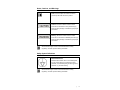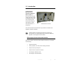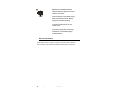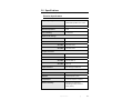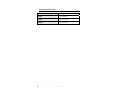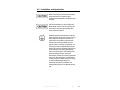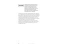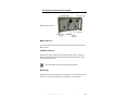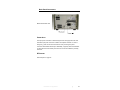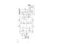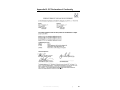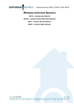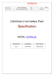
1
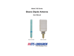
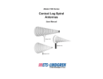
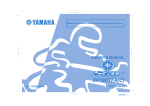
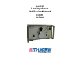
Model 3810/2
Line Impedance
Stabilization Network
(LISN)
User Manual
ETS-Lindgren L.P. reserves the right to make changes to any product described
herein in order to improve function, design, or for any other reason. Nothing
contained herein shall constitute ETS-Lindgren L.P. assuming any liability
whatsoever arising out of the application or use of any product or circuit
described herein. ETS-Lindgren L.P. does not convey any license under its
patent rights or the rights of others.
© Copyright 1996–2010 by ETS-Lindgren L.P. All Rights Reserved. No part
of this document may be copied by any means without written permission
from ETS-Lindgren L.P.
Trademarks used in this document: The ETS-Lindgren logo is a trademark of
ETS-Lindgren L.P.
Revision Record | MANUAL 3810/2 | Part #399197, Rev. D
Revision
Description
A–C
• Initial Release
Date
• Edits/updates
D
• Edits/updates
February, 1996
Rebrand; added EC Declaration of
July, 2010
Conformity
ii
|
Table of Contents
Notes, Cautions, and Warnings ................................................ v Safety Symbol Definitions......................................................... v 1.0 Introduction .......................................................................... 7 ETS-Lindgren Product Information Bulletin ................................................... 7 2.0 Maintenance ......................................................................... 9 Service Procedures ..................................................................................... 10 3.0 Specifications..................................................................... 11 Electrical Specifications ............................................................................... 11 Physical Specifications ................................................................................ 12 4.0 Installation and Application .............................................. 13 Front Panel Connectors and Controls ......................................................... 15 BNC Connector.................................................................................... 15 Line Select Switch ............................................................................... 15 RF Ground ........................................................................................... 15 Earth Line Choke Switch ..................................................................... 16 AC Receptacle ..................................................................................... 16 Artificial Hand....................................................................................... 16 Back Panel Connectors ............................................................................... 17 Power Input.......................................................................................... 17 RF Ground ........................................................................................... 17 5.0 Data ..................................................................................... 19 6.0 Schematic ........................................................................... 21 Appendix A: Warranty ............................................................. 23 Appendix B: EC Declaration of Conformity .......................... 25 |
iii
This page intentionally left blank.
iv
|
Notes, Cautions, and Warnings
Note: Denotes helpful information intended to
provide tips for better use of the product.
Caution: Denotes a hazard. Failure to follow
instructions could result in minor personal injury
and/or property damage. Included text gives proper
procedures.
Warning: Denotes a hazard. Failure to follow
instructions could result in SEVERE personal injury
and/or property damage. Included text gives proper
procedures.
See the ETS-Lindgren Product Information Bulletin for safety,
regulatory, and other product marking information.
Safety Symbol Definitions
EQUIPOTENTIALITY
Identifies the terminals, when connected together,
to bring various parts of a system to the same
potential, not necessarily being the earth (ground)
potential, e.g. for local bonding.
See the ETS-Lindgren Product Information Bulletin for safety,
regulatory, and other product marking information.
|
v
This page intentionally left blank.
vi
|
1.0 Introduction
The ETS-Lindgren
Model 3810/2 Line
Impedance Stabilization
Network (LISN) is a
two-channel low pass filter
network designed to isolate
the Equipment Under Test
from an external power
source while steering any
radio frequency signals
from the power line to a
Model 3810/2 Front View
50-ohm port.
The conducted emissions measurements may be made in accordance with
regulatory compliance standards
The Model 3810/2 was designed and tested in accordance with
IEC Publication 1010, Safety Requirements for Electronic Measuring
Apparatus, and is supplied in a safe condition.
ETS-Lindgren Product Information Bulletin
See the ETS-Lindgren Product Information Bulletin included with your shipment
for the following:
•
Warranty information
•
Safety, regulatory, and other product marking information
•
Steps to receive your shipment
•
Steps to return a component for service
•
ETS-Lindgren calibration service
•
ETS-Lindgren contact information
Introduction
|
7
This page intentionally left blank.
8
|
Introduction
2.0 Maintenance
Before performing any maintenance,
follow the safety information in the
ETS-Lindgren Product Information
Bulletin included with your shipment.
Only trained service personnel should
perform adjustments and/or service
procedures.
WARRANTY
Inside the Model 3810/2 are LETHAL
voltages with which you could come into
contact. Capacitors inside the unit may
still be CHARGED even when the unit is
disconnected from power.
Before Servicing contact ETS-Lindgren.
Servicing (or modifying) the unit yourself
may void your warranty. If you attempt to
service the unit yourself, disconnect all
electrical power before starting. There are
voltages at many points in the instrument
which could, if contacted, cause personal
injury. Only trained service personnel
should perform adjustments and/or
service procedures upon this instrument.
Maintenance
|
9
Maintenance of the Model 3810/2 is
limited to external components such as
cables or connectors.
Clean the exterior of the cabinet using a
damp cloth and mild cleaner. Always
unplug the unit before cleaning.
To prevent electrical shock, do not
remove cover.
If you have any questions concerning
maintenance, contact ETS-Lindgren
Customer Service.
Service Procedures
For the steps to return a system or system component to ETS-Lindgren for
service, see the Product Information Bulletin included with your shipment.
10
|
Maintenance
3.0 Specifications
Electrical Specifications
Frequency Range:
9 kHz–30 MHz
(VDE 0876 specified curve ± 20%
Network Inductance:
50 µH / 250 µH
Network Impedance:
50 Ω
Current Rating:
10 Amperes
Maximum AC Voltage
3810/2NM:
125 VAC 60 Hz
3810/2BR:
250 VAC 50 Hz
3810/2SH:
250 VAC 50 Hz
3810/2AS:
250 VAC 50 Hz
3810/2NM:
NEMA 5-15R
3810/2BR:
British BS1363
3810/2SH:
Schuko CEE 7/7
3810/2AS:
AS 3112
Output Connectors
Input Connector:
IEC-320 Type 3-wire Inlet
Environmental
Installation:
Indoor use only
Altitude:
15000 ft (4572 m) max
Temperature:
0°C to 40°C (32°F to 104°F)
Relative Humidity:
80% up to 31°C (87.8°F)
decreasing linearly to 50% at
40°C (104°F)
Specifications
|
11
Physical Specifications
12
Height:
124 mm (4.9 in)
Width:
218 mm (8.6 in)
Depth:
381 mm (15.0 in)
Weight:
5.4 kg (12.0 lb)
|
Specifications
4.0 Installation and Application
Before connecting any components, follow the
safety information in the ETS-Lindgren
Product Information Bulletin included with your
shipment.
Overcurrent protection is not provided in the
Model 3810/2. The unit must be connected to a
power mains which has appropriately rated
mains protection installed.
The Model 3810/2 is provided with a protective
earthing ground integral to the power cord. The
mains plug should only be connected to an
outlet which incorporates a protective earth
contact. Due to the high leakage current to
ground inherent in this type of equipment, it is
necessary to install a supplemental protective
earthing wire from the protective earth terminal
on the rear panel to an appropriate earthing
point on the power mains. This earthing point
should be determined by an electrician
authorized to perform such work by appropriate
code or law. Any interruption of the protective
conductor inside or outside of the unit is likely
to make the Model 3810/2 dangerous.
Intentional interruption is prohibited. The
supplemental ground wire is supplied with the
unit.
Installation and Application
|
13
The Model 3810/2 is provided with resistors to
help bleed off high voltage transients, but it is
advisable to connect the input and output
connectors to their proper power lines and
loads before connecting the monitor port to the
measurement instrumentation; otherwise,
power surges or transients can damage the test
instrumentation mixers or attenuators.
The Model 3810/2 Line Impedance Stabilization Network (LISN) is designed for
use in Installation Category II and Pollution Degree II per lEC-1010 and IEC-664.
When installing in a cabinet, make sure that the convection around the product is
not restricted. The ambient temperature outside the cabinet must be less than
the maximum operating temperature of the Model 3810/2 by 4°C for every
100 watts dissipated in the cabinet. If the total power dissipated in the cabinet is
greater than 800 watts, then forced convection must be used.
The Model 3810/2 is nominally designed for a 10 ampere current capacity.
Maximum line-to-line voltage must not exceed the voltage rating of the power
outlet provided on the front panel. See Specifications on page 11 for the
applicable maximum value.
14
|
Installation and Application
Front Panel Connectors and Controls
Model 3810/2 Front View
BNC CONNECTOR
Connect the Model 3810/2 to the spectrum analyzer or EMI receiver through the
BNC connector.
LINE SELECT SWITCH
Select the line to be monitored by the two-position selector switch. The line not
selected is internally terminated into 50 ohms. Switching between the two lines
will not generate transients.
Remove the BNC connection before disconnecting power.
RF GROUND
The Model 3810/2 is provided with an RF bonding stud on both the front and rear
panels. The unit should be bonded to a ground plane in normal operation.
Installation and Application
|
15
EARTH LINE CHOKE SWITCH
The safety ground isolation choke selector switch switches the 1.6 mH earth line
choke IN and OUT of the safety ground circuit. The ground choke is designed
and manufactured with sufficient capacity to conduct the maximum current rating
of the Model 3810/2 and at no time is the safety ground of the unit compromised.
The earth line choke avoids a double RF ground connection (safety ground and
measurement ground) in the conducted emissions test setup.
AC RECEPTACLE
Connect the Equipment Under Test (EUT) to the panel-mounted AC receptacle.
The style of receptacle is determined by the model specified. Following are the
standard output receptacle types:
•
NEMA (Type 5-15R)
•
Schuko (Type CEE 7/7)
•
British Standard (BS 1363)
•
Australian (AS 3112)
ARTIFICIAL HAND
In conformance with EN55014 and BS800, the artificial hand connection is used
to test handheld equipment that is provided without earth connections.
16
|
Installation and Application
Back Panel Connectors
Model 3810/2 Back View
POWER INPUT
The input power connection is made through the IEC-320 type power inlet. This
three-wire input power connector is rated at 10 amperes maximum. In case of
emergency, power can be removed from the unit by removing the power
connection at the Model 3810/2 input. Alternately, a properly rated circuit breaker
or switch which removes mains power from the unit can be installed in proximity
to the unit.
RF GROUND
See description on page 15.
Installation and Application
|
17
This page intentionally left blank.
18
|
Installation and Application
5.0 Data
Graphs of the calibration data for each measurement port of the Model 3810/2
Line Impedance Stabilization Network (LISN) are included with the unit. The
graphs provide individual plots of both impedance and insertion loss data.
Impedance is plotted in a semi-log format where frequency is displayed on the
horizontal from 9 kHz to 30 MHz. The vertical has a range of 0 ohms to
100 ohms and represents the measured impedance of the unit. The insertion loss
is also plotted with frequency on the horizontal from 9 kHz to 30 MHz. The
vertical of the graph has a range of -9 dB to 1 dB and represents the measured
insertion loss of the Model 3810/2.
A Certificate of Calibration Conformance is provided with each Model 3810/2.
Data
|
19
This page intentionally left blank.
20
|
Data
6.0 Schematic
• Resistance values shown in ohms.
• Ground choke select switch (S1) shown in the IN position.
• Line monitor select switch (S2) shown in the L2 (NTL) position.
• NEMA type output connector shown.
Schematic
|
21
22
|
Schematic
Appendix A: Warranty
See the Product Information Bulletin included with your shipment for
the complete ETS-Lindgren warranty for your Model 3810/2.
DURATION OF WARRANTIES FOR MODEL 3810/2
All product warranties, except the warranty of title, and all remedies for warranty
failures are limited to two years.
Product Warranted
Duration of Warranty Period
Model 3810/2 Line Impedance
2 Years
Stabilization Network (LISN)
Warranty
|
23
This page intentionally left blank.
24
|
Warranty
Appendix B: EC Declaration of Conformity
EC Declaration of Conformity
|
25