1
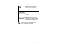
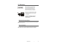
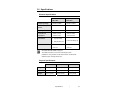
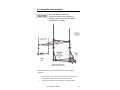
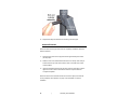
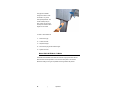
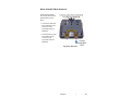
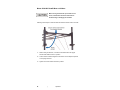
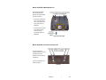
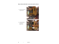
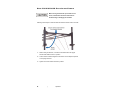
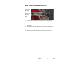
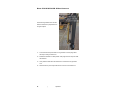
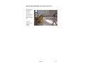
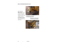
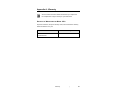
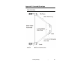
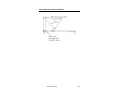
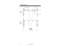
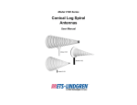
Model 5503 Series
E & H Field Generator
2-Meter, 3-Meter, 5-Meter
User Manual
Model 5503-5M shown
ETS-Lindgren L.P. reserves the right to make changes to any product described
herein in order to improve function, design, or for any other reason. Nothing
contained herein shall constitute ETS-Lindgren L.P. assuming any liability
whatsoever arising out of the application or use of any product or circuit
described herein. ETS-Lindgren L.P. does not convey any license under its
patent rights or the rights of others.
© Copyright 2005–2008 by ETS-Lindgren L.P. All Rights Reserved. No part
of this document may be copied by any means without written permission
from ETS-Lindgren L.P.
Trademarks used in this document: The ETS-Lindgren logo is a trademark of
ETS-Lindgren L.P.
Revision Record
MANUAL,5503 EH FIELD GENERATOR | Part #399773, Rev. B
Revision
Description
Date
A
Initial Release
November, 2005
B
Added 5503-2M & 5503-3M;
December, 2008
rebrand
ii
|
Table of Contents
Notes, Cautions, and Warnings ................................................ v 1.0 Introduction .......................................................................... 7 ETS-Lindgren Product Information Bulletin ................................................... 7 2.0 Maintenance ......................................................................... 9 Maintenance Recommendations ................................................................... 9 Service Procedures ....................................................................................... 9 3.0 Specifications..................................................................... 11 Electrical Specifications ............................................................................... 11 Physical Specifications ................................................................................ 11 4.0 Assembly and Installation ................................................ 13 Support Structure ......................................................................................... 14 Antenna Elements ....................................................................................... 16 Cables .......................................................................................................... 17 5.0 Operation ............................................................................ 19 Antenna Elements ....................................................................................... 19 Model 5503-5M E-Mode / H-Mode .............................................................. 20 Model 5503-5M: E-Mode Operation .................................................... 21 Model 5503-5M: From E-Mode to H-Mode .......................................... 22 Model 5503-5M: H-Mode Operation .................................................... 23 Model 5503-5M: Load Cable Connections .......................................... 23 Model 5503-5M: Grounding ................................................................. 24 Model 5503-2M & 5503-3M: E-Mode / H-Mode ........................................... 25 Model 5503-2m & 5503-3M: Change Low Power Balun Boxes .......... 26 Model 5503-2M & 5503-3M: Rotate Antenna Elements ...................... 28 Model 5503-2M & 5503-3M: E-Mode Operation .................................. 29 Model 5503-2M & 5503-3M: H-Mode Operation ................................. 30 Model 5503-2M & 5503-3M: Load Cable Connections ........................ 31 Model 5503-2M & 5503-3M: Grounding .............................................. 32 Typical Test Setup ....................................................................................... 33 Model 5503-5M VSWR ........................................................................ 33 Model 5503-5M Power Requirements, 100 V/M .................................. 34 Storage ........................................................................................................ 34 |
iii
Appendix A: Warranty ............................................................. 35 Appendix B: Assembly Drawings .......................................... 37 Frame Assembly .......................................................................................... 37 Element Installation ..................................................................................... 38 Framing Element (Strut) Installation ............................................................ 39 Antenna Orientation ..................................................................................... 40 iv
|
Notes, Cautions, and Warnings
Note: Denotes helpful information intended to
provide tips for better use of the product.
Caution: Denotes a hazard. Failure to follow
instructions could result in minor personal injury
and/or property damage. Included text gives proper
procedures.
Warning: Denotes a hazard. Failure to follow
instructions could result in SEVERE personal injury
and/or property damage. Included text gives proper
procedures.
See the ETS-Lindgren Product Information Bulletin for safety,
regulatory, and other product marking information.
|
v
This page intentionally left blank.
vi
|
1.0 Introduction
The ETS-Lindgren Model 5503 Series E&H Field Generator creates a vertical
or horizontal electric field. This two-conductor transmission line system consists
of parallel radiating elements attached to a non-conductive, non-metallic frame,
as well as a load and balun boxes that are mounted on the frame and attached to
the ground plane. The Model 5503 is available in three sizes: 2-meter, 3-meter,
and 5-meter.
The two operating modes of the field generator are:
•
E-Mode (Common)—When the current on the two radiating elements
flows in the same direction, a vertical E-field is the dominant field
component. Field distribution simulates that of a quasi-static
parallel-plate transverse electromagnetic mode (TEM).
•
H-Mode (Differential)—When the current on the two radiating
elements flows in the opposite direction, a vertical H-field or a
horizontally polarized E-field is the dominant field component. Field
distribution is approximately that of a quasi-static two-wire transmission
line. A balun is used to isolate the elements from the ground plane.
The Model 5503-2M and Model 5503-3M include two plug-in low power
balun boxes, one for E-field operation and one for H-field operation. The
Model 5503-5M includes one high power balun box for either E-field operation or
H-field operation.
ETS-Lindgren Product Information Bulletin
See the ETS-Lindgren Product Information Bulletin included with your shipment
for the following:
•
Warranty information
•
Safety, regulatory, and other product marking information
•
Steps to receive your shipment
•
Steps to return a component for service
•
ETS-Lindgren calibration service
•
ETS-Lindgren contact information
Introduction
|
7
This page intentionally left blank.
8
|
Introduction
2.0 Maintenance
Before performing any maintenance,
follow the safety information in the
ETS-Lindgren Product Information
Bulletin included with your shipment.
WARRANTY
Maintenance of the Model 5503 is limited
to external components such as cables
or connectors.
If you have any questions concerning
maintenance, contact ETS-Lindgren
Customer Service.
Maintenance Recommendations
Periodically check for wear on the cables that extend from the antenna elements
to the load and balun boxes.
Service Procedures
For the steps to return a system or system component to ETS-Lindgren for
service, see the Product Information Bulletin included with your shipment.
Maintenance
|
9
This page intentionally left blank.
10
|
Maintenance
3.0 Specifications
Electrical Specifications
Low Power
High Power
Balun Box
Balun Box
Frequency Range:
100 kHz–30 MHz
100 kHz–30 MHz
Continuous Input
1 kW
3 kW
Input Impedance:
50 Ω
50 Ω
Transmit Line
~200 Ω H-mode
~200 Ω H-mode
Impedance:
~100 Ω E-mode
~100 Ω E-mode
Connectors:
• Type N, female
Power:
• One per balun box
VSWR:
1 5/8-in EIA flange (2)
<3.25:1 H
<3.25:1 H
<4.25:1 E
<4.25:1 E
See Model 5503-5M VSWR on page 33.
The VSWR is less than 2.5 for most of the range for both
polarizations. The generator can be used as low as 10 kHz but the
VSWR is higher, reaching values of 9:1.
Physical Specifications
2-Meter
3-Meter
5-Meter
Length:
4.65 m (15.25 ft)
5.64 m (18.5 ft)
7.65 m (25.0 ft)
Width:
1.79 m (5.9 ft)
1.79 m (5.9 ft)
1.79 m (5.9 ft)
Height:
2.75 m (9.0 ft)
2.75 m (9.0 ft)
2.75 m (9.0 ft)
Specifications
|
11
This page intentionally left blank.
12
|
Specifications
4.0 Assembly and Installation
Before assembling or installing any
components, follow the safety information in
the ETS-Lindgren Product Information Bulletin
included with your shipment.
Model 5503-5M shown
with high power balun box
The Model 5503 Series E & H Field Generator consists of the following
components:
•
Non-conductive, non-metallic support structure, including four masts
that enable the vertical movement of the element carriers.
•
Two antenna elements, each consisting of a rectangular frame.
Assembly and Installation
|
13
•
Elements connect to a load box and a balun box through radiating
element wire bundles. Each radiating element wire bundle assembly
consists of two pieces of conductive braid over rope and a spring
retraction system housed in an aluminum tube assembly.
A metal ground plane with minimum dimensions of 8 m x 3 m x 1/16 in
(not included) must be centered under the Model 5503.
Support Structure
A minimum of four people are required to safely
assemble and operate the Model 5503.
See Assembly Drawings on page 37 for additional assembly and
installation illustrations.
The support structure is shipped partially assembled. To complete assembly, set
the vertical supports upright and secure with framing elements (struts).
1. Unfold the support structure
so that the masts and
element supports are
straight and at 90 degrees to
the base.
14
|
Assembly and Installation
2. Rotate the two framing
elements and insert them
into the receiving brackets
on the upright elements.
3. Insert the bolt assembly into
each framing element: Insert
the cylinder or bushing
through the hole and then
insert the bolt and fasten it
on both sides with the nuts.
Assembly and Installation
|
15
4. Repeat these steps to assemble the remaining vertical support.
Antenna Elements
When both sides of the support structure are completely assembled, attach the
antenna elements:
1. Space the two pieces of the support structure approximately five meters
(16 feet) apart.
2. Slide the ends of the antenna elements into the two clamps. One clamp is
located near the top of the carrier and the other on the side of the carrier
near the bottom.
3. Insert the threaded knobs through the holes near the outer edge, and then
tighten the knobs. These knobs hold the elements in place inside the
U-shaped receptacle.
When both ends of each antenna element are secured in place, the antennas
can be positioned. See Operation on page 19 for information on antenna
orientation.
16
|
Assembly and Installation
Cables
To protect your hands, use gloves when extending
or retracting the cables.
Four cables extend down to the load box and balun box from the ends of
each radiating element. These cables must be disconnected and
reconnected each time the radiating elements are moved up and down,
when changing from E-field mode to H-field mode.
The cables extend from and
retract into the antenna
elements. The knob clamp
at each end of the element
ensures good contact.
Assembly and Installation
|
17
Each cable is terminated at a post on the load box or balun box. Only one cable
may be connected to each post. Secure the cable into place with a wing nut.
To connect the cables:
1. Loosen the knob clamp on the antenna element around the cable.
2. Pull the connecting loop out from the element and over to the
corresponding connection post on the load box or balun box.
3. Remove the nut and the top washer from the post and slide the
connecting loop into place on the post then replace the washer and nut.
Securely tighten the nut for good contact.
4. Tighten the knob clamp on the antenna element around the cable.
18
|
Assembly and Installation
5.0 Operation
Before connecting any components or
operating the Model 5503, follow the safety
information in the ETS-Lindgren
Product Information Bulletin included with your
shipment.
Testing with the Model 5503 should not be
conducted in an area where the field generated
could cause disruption to other equipment. This
unit must be used in a screen or shielded
enclosure.
The operator should limit exposure to the field
generated by this device.
Antenna Elements
Two conductor cables on each of the elements extend downward to connect the
elements to the load box and balun box. The conductive cables extend and
retract out of the elements depending on the distance to the connection point on
the load box and balun box. For more information, see Cables on page 17.
Four masts extend upward to allow the carriers to slide up and down. The masts,
in conjunction with the carriers and phenolic pins (pegs), allow vertical
adjustment to 1.5 m, 2 m, and 2.5 m.
Operation
|
19
The pegs are installed
through the masts to hold
the carrier in any of the
three preset positions. The
carrier handle (knob) on
each carrier can be turned
to clamp the carrier at other
heights on the masts.
To raise or lower elements:
1. Remove the peg.
2. Loosen the knob.
3. Adjust the height.
4. Re-insert the peg for the desired height.
5. Tighten the knob.
Model 5503-5M E-Mode / H-Mode
The Model 5503-5M E&H Field Generator includes a high power balun box for
either E-field or H-field operation. The connectors and posts on the box are
labeled according to the type of operation that the generator will perform.
20
|
Operation
MODEL 5503-5M: E-MODE OPERATION
The E-field is generated
when the two elements are
parallel with the ground
plane.
• Connect the cables from
the two elements to the
center post on the
high power balun box
labeled E.
• Connect the RF or power
input cable to the RF
connector on the
high power balun box
labeled E.
High Power Balun Box
Operation
|
21
MODEL 5503-5M: FROM E-MODE TO H-MODE
When moving the elements up and down on the
carrier, maintain the same level at all times to
avoid bending or damaging the elements.
Following are the steps to rotate the antenna elements from E-mode to H-mode:
1. While holding the element, unscrew the bolt farthest from the upright
element that holds the frame in position.
2. Let the element rotate 90 degrees until it rests in the U-shaped receptacle
on the upright element.
3. Tighten the bolt to hold the element in position.
22
|
Operation
MODEL 5503-5M: H-MODE OPERATION
The H-field is generated
when the two antenna
elements are perpendicular
to the ground plane.
• Connect the cables from
each of the elements to
each of the posts on the
high power balun box
labeled H.
• Connect the RF or power
input cable to the RF
connector on the
high power balun box
labeled H.
High Power Balun Box
MODEL 5503-5M: LOAD CABLE CONNECTIONS
For both E-mode and
H-mode operations, connect
the cables from each
element to the two posts on
the load box.
For more information, see
Cables on page 17.
Load Box
Operation
|
23
MODEL 5503-5M: GROUNDING
Before operating the
Model 5503-5M, verify that
the ground contact foot on
the load box and balun box
is attached to ground, and is
grounded. This can be
accomplished by using bolts
(not included) that screw
onto the ground plane in the
shielded room.
24
|
Operation
Model 5503-2M & 5503-3M: E-Mode / H-Mode
The Model 5503-2M and
Model 5503-3M include one
low power balun box for
E-field operation and one
low power balun box for
H-field operation. Each box
is labeled accordingly.
Operation
|
25
MODEL 5503-2M & 5503-3M: CHANGE LOW POWER BALUN BOXES
1. Open clip on each side
of generator unit.
2. Carefully slide balun
box away from
generator unit.
26
|
Operation
3. Slide other balun box
toward generator unit
so that it is flush with
the unit.
4. Close clips on both sides to secure the balun box into place.
Operation
|
27
MODEL 5503-2M & 5503-3M: ROTATE ANTENNA ELEMENTS
When moving the elements up and down on the
carrier, maintain the same level at all times to
avoid bending or damaging the elements.
Following are the steps to rotate the antenna elements from E-mode to H-mode:
1. While holding the element, unscrew the bolt farthest from the upright
element that holds the frame in position.
2. Let the element rotate 90 degrees until it rests in the U-shaped receptacle
on the upright element.
3. Tighten the bolt to hold the element in position.
28
|
Operation
MODEL 5503-2M & 5503-3M: E-MODE OPERATION
The E-field is
generated
when the two
elements are
parallel with
the ground
plane.
1. Connect E-field low power balun box to generator unit. See page 26 for
the steps to change a balun box.
2. Rotate the elements to E-field position. See page 28 for the steps to rotate
the elements.
3. Verify that the cables from the elements are connected to the generator
unit.
4. Attach the RF or power input cable to the connector on the balun box.
Operation
|
29
MODEL 5503-2M & 5503-3M: H-MODE OPERATION
The H-field is generated when the two
antenna elements are perpendicular to
the ground plane.
1. Connect H-field low power balun box to generator unit. See page 26 for
the steps to change a balun box.
2. Rotate the elements to H-field position. See page 28 for the steps to rotate
the elements.
3. Verify that the cables from the elements are connected to the generator
unit.
4. Attach the RF or power input cable to the connector on the balun box.
30
|
Operation
MODEL 5503-2M & 5503-3M: LOAD CABLE CONNECTIONS
For both E-mode
and H-mode
operations,
connect the
cables from each
element to the
posts on the load
box.
For more
information, see
Cables on
page 17.
Operation
|
31
MODEL 5503-2M & 5503-3M: GROUNDING
Before operating the
Model 5503-2M or
Model 5503-3M, verify that
the ground contact foot on
the load box and balun box
is attached to ground, and is
grounded. This can be
accomplished by using bolts
(not included) that screw
onto the ground plane in the
shielded room.
32
|
Operation
Typical Test Setup
MODEL 5503-5M VSWR
Operation
|
33
MODEL 5503-5M POWER REQUIREMENTS, 100 V/M
Storage
The Model 5503 provides convenient storage when testing is complete.
1.
Disconnect all cables, including those that attach the antenna elements
to the load box and balun box.
2.
Remove the bolts that connect the elements to the U-shaped brackets.
3.
Disconnect the grounding plates.
4.
Roll the two sections of the support structure and carry the elements to
the storage location.
34
|
Operation
Appendix A: Warranty
See the Product Information Bulletin included with your shipment for
the complete ETS-Lindgren warranty for your Model 5503.
DURATION OF WARRANTIES FOR MODEL 5503
All product warranties, except the warranty of title, and all remedies for warranty
failures are limited to one year.
Product Warranted
Duration of Warranty Period
Model 5503 Series E&H
1 Year
Field Generator
Warranty
|
35
This page intentionally left blank.
36
|
Warranty
Appendix B: Assembly Drawings
Frame Assembly
Assembly Drawings
|
37
Element Installation
38
|
Assembly Drawings
Framing Element (Strut) Installation
Assembly Drawings
|
39
Antenna Orientation
40
|
Assembly Drawings