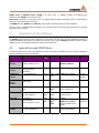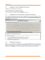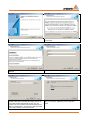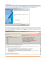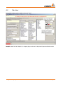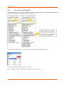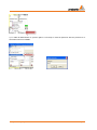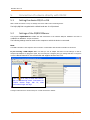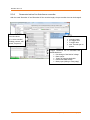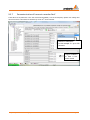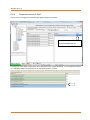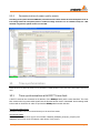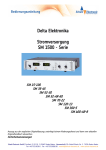
1
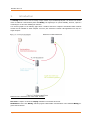
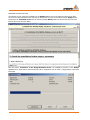
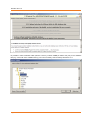
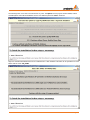
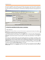
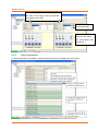
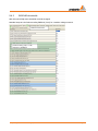
Commissioning Instructions WinPQ Evaluation Software and PQI-D/PQIDA Measuring Systems WinPQ Para Express (only chapter 9) Software WinPQ We take care of it Notes on the commissioning instructions: After installing the WinPQ software and the MySQL database in sections 2 and 3 of the instructions, select one of the chapters highlighted in colour for data communication between the software and the measuring devices. The selected section (e.g. 6. Device Connection via TCP/IP) describes the required operating steps for the software and hardware. Any other, alternative chapters for connecting a device can be skipped. If different communication paths are to be operated in parallel, work through all points of the respective data connections used (e.g. MODEM and TCP/IP). WinPQ Para Express Additional to WinPQ there is a small software WinPQ Para Express available only for setup the parameters in PQI-D and PQI-DA. This software is free of charge and available on www.a-eberle.de. All settings for the hardware could be made with this software. It is possible to check with online data the correct connection of the device. It is possible to start this SW directly from an USB-stick. Please use all information from chapter 9. A. Eberle GmbH & Co. KG Aalener Straße 30/32 D-90441 Nuremberg Tel.: 0911 / 62 81 08 0 Fax: 0911 / 62 81 08 96 E-Mail: [email protected] Internet: www.a-eberle.de A.-Eberle GmbH & Co. KG cannot be held liable for any damage or losses resulting from printing errors or changes to this operating manual. Furthermore, A. Eberle GmbH & Co. KG does not assume responsibility for any damage or losses resulting from defective devices or from devices altered by the user. Copyright 2010 by A. Eberle GmbH & Co. KG All rights reserved. Page 2 Content 1. Introduction ..................................................................................................................... 6 2. Installation of the Software .............................................................................................. 7 2.1 Index of the used TCP/IP-Ports .................................................................................................7 2.2 Installation of the Database (File Server)..................................................................................8 2.3 Installation of a Client (Further Evaluation Computer) ............................................................8 2.4 Installation Procedure ...............................................................................................................8 3. The WinPQ Control Center: The Program PQStart ........................................................... 15 3.1 Representation of PQI-D Devices in PQStart ..........................................................................15 3.1.1 Create new stations, groups and tabs ....................................................................................15 3.1.2 Changing the device name and ID number.............................................................................17 3.1.3 Alerting – Optically, Acoustically, or by E-Mail .......................................................................17 3.1.4 Hiding of Program Functions ..................................................................................................18 3.2 Connecting an additional evaluation computer to the database ...........................................19 3.2.1 Connection of a client to the database ...................................................................................19 3.2.2 Connection of an additional evaluation computer for online data and parameterization ....21 4. Settings in WinPQ – PQ Admin ........................................................................................ 21 4.1 Tab: SQL ..................................................................................................................................22 4.2 Tab: User .................................................................................................................................23 4.3 User with limited rights...........................................................................................................24 5. Connection of a device directly with RS232 ..................................................................... 26 5.1 Setting the device PQI-D or DA ...............................................................................................26 5.2 Settings of the PQRS232Server ...............................................................................................26 5.3 Settings in the “PQManager” ..................................................................................................27 6. Device Connection via TCP/IP ......................................................................................... 29 6.1 Setting the interface of the device .........................................................................................29 6.1.1 TCP/IP Connection through W&T COM-Server.......................................................................31 6.2 Settings of the “PQRS232Server”............................................................................................32 6.3 Settings in the “PQManager” ..................................................................................................33 7. Device Connection via Dial-Up MODEM .......................................................................... 35 7.1 Setting the device ...................................................................................................................35 7.1.1 Setting the interface of the PQI-D ..........................................................................................35 7.2 Setting the MODEM on the PQI-D side ...................................................................................37 7.3 Setting the Remote MODEM ..................................................................................................38 7.4 Settings of the “RS232Server” ................................................................................................38 Content Page 3 We take care of it 7.5 Configuration of the WinPQ Software .................................................................................... 39 8. The WinPQ Management Programs in Continuous Operation ......................................... 40 8.1 Windows Task Scheduler ........................................................................................................ 40 8.2 The Management Programs in Continuous Operation........................................................... 41 8.3 Setting PQManager to Continuous Operation:....................................................................... 41 8.4 Setting the PQRS232Server to Continuous Operation ........................................................... 42 8.5 Setting PQRvReport to Continuous Operation: ...................................................................... 42 9. Setup and parameterization – PQI-D/DA ......................................................................... 42 9.1 Setup with PQ Para Express .................................................................................................... 42 9.2 Setup with WinPQ ................................................................................................................... 43 9.3 ID, LAN, Time .......................................................................................................................... 45 9.3.1 Time synchronization .............................................................................................................. 45 9.3.2 ECL commands ........................................................................................................................ 46 9.3.3 ELAN structure ........................................................................................................................ 47 9.4 Thresholds, connection, IO ..................................................................................................... 47 9.4.1 Special parameter ................................................................................................................... 48 9.4.2 EN50160 thresholds................................................................................................................ 49 9.4.3 Transnostic .............................................................................................................................. 50 9.4.4 Option M94/M95 – analogue output ..................................................................................... 51 9.4.5 Option M97/M98 analogue inputs ......................................................................................... 52 9.4.6 Binary inputs ........................................................................................................................... 53 9.4.7 Messages on Relays and LED´s ............................................................................................... 54 9.5 Measuring parameter / trigger ............................................................................................... 55 9.5.1 Status of LED´s, relays and binary inputs ................................................................................ 56 9.5.2 Online panel ............................................................................................................................ 56 9.5.3 Vector diagram ....................................................................................................................... 56 9.5.4 Parameterization of continues classes ................................................................................... 57 9.5.5 Parameterisation of disturbance recorder ............................................................................. 59 9.5.6 Parameterisation for disturbance recorder ............................................................................ 60 9.5.7 Parameterization of harmonic recorder RecC ........................................................................ 61 9.5.8 Parameterisation of RecS........................................................................................................ 62 9.5.9 Parameterization of power quality events ............................................................................. 63 10. Time synchronization ...................................................................................................... 63 10.1 Time synchronisation with DCF77 time clock ......................................................................... 63 10.2 Time synchronisation with GPS time clock ............................................................................. 64 10.3 Interface settings for time clock connected to RS232 ............................................................ 64 Page 4 Content 10.4 Interface settings for the GPS clock connected at the time bus.............................................65 10.5 Setting up the synchronization with E-LAN connection .........................................................65 11. Firmware update PQI-D and PQI-DA ............................................................................... 67 12. Setting of the PQ-Mail .................................................................................................... 71 13. Automatically print or e-mail order................................................................................. 72 13.1 Automatically generated disturbance reports ........................................................................72 13.2 Automatic power quality reports............................................................................................73 13.3 Mail order automatic reports .................................................................................................74 Content Page 5 We take care of it 1. Introduction The WinPQ software can be used to manage a large number of pre-installed PQI-Ds/DAs. The devices can communicate via different communication paths with WinPQ. The high degree of system flexibility, however, requires a certain degree of care when installing the software. The overview graphic on the following page shows a situation with three computers and indicates which software module must be installed on which computer. Of course, the overhead is reduced if the application runs only on a single computer. Remark on the excessive use of the word “Server”: File server: Computer on which the “MySQL” database runs and data are stored. RS232Server: Part of the “WinPQ” software program which handles communication of the individual WinPQ programs with the devices. Page 6 Introduction MySQL server or database server: MySQL is an “SQL server”, i.e. database software for managing large amounts of data. MySQL runs on the file server. COM server: Hardware, e.g. from W&T. This is an adaptor between RS232 and TCP/IP, which is used whenever PQI-Ds are to be connected via a network. The REGSys devices “REG-PE” and “REG-P” (control system connection) also have this functionality. The term “server” is avoided in these instructions. The respective term from this list is used instead. Thus it is always clear which server is meant. 2. Installation of the Software The WinPQ software package manly comprises two components: the SQL server and the visualisation software. A complete installation only needs to be carried out on the file server. Only the WinPQ visualisation software without database needs to be installed on the control station and connection PC. 2.1 Index of the used TCP/IP-Ports The following table shows a list of all TCP/IP-Ports used in this System. Depending from your system configuration and the hardware the ports can be different. Programm Zweck Server/ Vorschlag Kommunikation mit … Änderung Client Communication with MySQL- database server Server 3306 PQManager, PQVisu, PQStart, PQReport Remote Parametrization (Changing RS232Parameter) Server 8000 Telnet INI-File (service) RS232Server Access RS232-Ports Server 1701, usw. PQManager, PQPara INI-File, MySQL (service) RS232Server (service) PQReport, PQVisu, PQStart PQPara PQManager WuT-COM Remote Desktop RDP 1702 PQStart Read and visualize of MySQL-data Client 3306 MySQL-service Read and change of PQI-D setup Client 1701 usw. RS232Server 8000 … WuT-COM-Server Transfers data from E-LAN Client 1700 … RS232-/COM-Server Into SQL-database Client 3306 MySQL-service COM-Serverparametrization Client 1111 Telnet Fix Client COM-SVR 8000 PQManager, PQPara Communication to E-LAN 8888 Software-COM-ServerReset Access via „Remote Desktop“ (MS- Windows ©) 3389 Remote access via operating system abilities INI-File INI-File Overview of program components Installation of the Software Page 7 We take care of it 2.2 Installation of the Database (File Server) Installation of the complete package on the file server. Proceed as described in section 2.3 of these instructions. Note down the IP address or the BIOS name of the file server. In some circumstances, the Windows command “IPCONFIG” may be useful. 2.3 Installation of a Client (Further Evaluation Computer) When installing an additional evaluation computer without a database, the client accesses the database on the file server (alternatively it's possible to transfer the '..\winpq' directory by Copy & Paste to the next computer). Proceed as described in the next section of these instructions. Activate the option ,Continue without installation of MySQL-Database' in the dialog below. Main menu of the installation screen 2.4 Installation Procedure The file WinPQ.exe is supplied on the installation CD. It is a self-extracting installation file, which is unzipped and started by double-clicking on it (or by selecting it and pressing ENTER). First, the usual start screen form is displayed. If no license number or an invalid license number is entered three times in a row, the software can be installed and used as a DEMO version. This version is restricted, access to real PQI-D stations is not possible. Page 8 Installation of the Software First you find the usual welcome dialog. You should then read the license agreement carefully and accept it. Then a few notes on carrying out the installation are displayed. Now the software can be registered under your name. Select a different directory if it's necessary. Less than 300 MB of disk space (including the setting data or device profiles created subsequently by the user) are required. The save location of the actual measurement data is not defined here. The amount of data generated by the PQI-D stations can be ignored here. The installation process is now in progress. This can take 1 to 5 minutes, depending on the computer’s speed. Installation of the Software Page 9 We take care of it Once all of the data have been copied, a tool from the WinPQ environment is automatically started. This can be used to set up the future program behaviour. Therefore do never change the check box 'Run WiPQ now'. Before further steps can be taken, the license number must first be entered. This can be found on the license certificate in the folder containing the documentation. If no license number or an invalid license number is entered three times in a row, the software can be installed and used as a DEMO version. This version is restricted, access to real PQI-D stations is not possible. Page 10 Installation of the Software Installation screen license code The following screens support the installation of the MySQL-database-server and important options of the basic setup can be selected. But before the next step can be launched, you have to read and accept the MySQL license agreement as an embedded version into the software package WinPQ. Notice the buttons have the same numbers like the text in the memo below. With the button „Installation of the MySQL-Dateabase-server“ the installation procedure of the MySQLDatabase-server will be started. All necessary files will be unzipped into the sub folder '..\winpq\MySQL' of the installation path. Installation of the Software Page 11 We take care of it It's possible to select a different folder (assume a memory of about 500MB per Station and year) for the database data (e.g. a drive with more available memory). If this isn't necessary continue directly with button 2.2.2. Page 12 Installation of the Software The following button 2.2.2 have to be executed in any case. The MySQL-service program will be installed, started and PQ-MySQL-users will be established. For the user 'root' the password 'admin' will be set. Right now the delivered DEMO-Data can be transferred into a SQL database. This data can be operated from a database with the name 'PQ_DEMO'. Installation of the Software Page 13 We take care of it Afterwards the installations routine changes to the page 'Basic-setup'. Mostly you can left the selection unchanged. If you want to operate in a an multi user environment (e.g. Citrix) with different setup of each user or several user at the same time the selection %UserProfile% is recommended. By confirming the selection the third page will be activated. Several important settings can be made via the following screen form. To differentiate between the station data, the ID of the PQI-D stations is usually used. When parameterising the stations, ensure that IDs are not used twice, even if stations are not to be interconnected via the E-LAN. “Extended ID” means that this restriction is removed insofar as the station name (8 characters) is used in addition to the ID. In the centre area, important settings can be made regarding data access to the stations. An interface for direct access via RS232, a second one for communication using a MODEM, and a TCP/IP interface can be stored and parameterised. Based on these examples, further ports can subsequently be added directly in the INI file of the “PQRS232Server” by means of copy and paste. With the checkbox “Time syn. via PC”, it is defined that the PQID stations are synchronised daily with the PC time. The behaviour of the program is adapted to the preferred mode of operation by selecting “Access to PQI-D stations” (on the right). Finally, your company name can be entered. An image file with your logo can be assigned (the formats “jpg” and “bmp” are supported) later in the PQAdmin program (Tab: User setup). These settings are used for protocol printouts and similar. Page 14 Installation of the Software 3. The WinPQ Control Center: The Program PQStart This program represents the communication centre of WinPQ. Each individual PQI-D/DA is represented by a field which permits you to access the station directly. The most important functions of this program are: 3.1 Display of the identifier and any text that describes the associated station Via the menu (in the figure “SS1”, the text can be set as required), direct access to the station-related data in the database or the station itself Setting for access via MODEM It alerts the user when new PQ events/errors occur It reports PQ events and changes at the binary inputs Representation of PQI-D Devices in PQStart You can create a box for each device from which you can access the device directly. The station properties and labelling must be adapted to make it as easy as possible for subsequent users to assign the station. Right-click on the required station. Select “Properties: station” in the menu that appears. The central dialogue box for the link between this display and the devices is then displayed. 3.1.1 Create new stations, groups and tabs By clicking the right mouse button you have the following options: Station: Activate Station: Properties Station: Copy setup Station: Insert setup Station: New Station: Delete Group: Properties A station can be activated You can change the properties of each station You can copy the setup into clipboard You can insert properties from clipboard One can create a new station A station can be deleted here The properties of a group (sub station) can be changed The WinPQ Control Center: The Program PQStart Page 15 We take care of it Group: New Page: Change text Search for a station A new group can be generated The text of the page tab can be changed One can input a station name and the program searches for the item An example of station overview Page 16 The WinPQ Control Center: The Program PQStart 3.1.2 Changing the device name and ID number The most important points: The designations which you can enter in the field do not change your device settings. It is therefore not absolutely essential for the designation and the device name to be identical. The ID (e.g. “Q1”) must be entered correctly, because this ID is used as a filter when a program is started. In the field “Connections (SQL + TCP/IP)”, the connection to the RS232Server is generated by means of “Network-ID” and “Network port”, i.e. the direct access to the device for parameterisation and online data. The link to the database in the same field is created with “SQL connection” and “IP…”. “SQL connection” indicates which data are to be used. PQVisu Standard directory for PQI-D measurement data PQDemo Demo data for exemplifying and testing PQBox Data of the PQ-Box 1000 measuring devices 3.1.3 Select the SQL connection “PQVisu” as the default setting. The standard network ID is called “LocalHost” if the program PQRS232Server runs on the same PC. Alerting – Optically, Acoustically, or by E-Mail This permits alerting (optically and acoustically) when fault messages or binary signals (binary inputs of the PQI-D) are received. If alerting is activated, the status indicator colour changes from green to red when an event occurs In the dialogue box “Alert/Mail” you can set different alerting options for events on the PC. The WinPQ Control Center: The Program PQStart Page 17 We take care of it Windows sound will be heard from the PC, during an event. Quit = permanent sound till the event will be confirmed Recommendation: Recorder B – Optical alert 3.1.4 Hiding of Program Functions The scope of the menu functions can be limited. As with all other selection boxes, if no selection has been made, all functions and data can be accessed. Page 18 The WinPQ Control Center: The Program PQStart 3.2 Connecting an additional evaluation computer to the database 3.2.1 Connection of a client to the database Option 1: Open the station properties of any device. If no database is found, the button “IP” is activated. When this is clicked, an input window appears, into which the BIOS name or IP address of the server on which the database is installed can be entered. A connection has been established as soon as the status box on the bottom left is green. If it remains red, either the address is incorrect or there is a problem with the network. (For instance Firewall! Refer to the network checklist) In the Network-ID field, enter the address of the computer on which the program PQRS232Server is running. (Default setting “LocalHost”) The WinPQ Control Center: The Program PQStart Page 19 We take care of it Option 2: Open the file ..\WinPQ\dbxconnections.ini After each “HostName=”, enter the IP or the BIOS name of the file server. For example, HostName=StWX_Server1 or HostName= 192.168.1.1 If the PQStart program finds the database, the colour of status box on the bottom left is green and displays: “SQL: PQID@Servername” Information for the administrator: To contact the SQLServer, the clients use Port 3306. If you set the “SQL connection” to PQDemo, demo data are displayed which will help you become accustomed in the beginning when actual data is not available yet. Page 20 The WinPQ Control Center: The Program PQStart 3.2.2 Connection of an additional evaluation computer for online data and parameterization These settings are only required if you want to access devices (PQI-D/-DA) online from this client. A functional access to the database is sufficient for visualising data. Open the station properties. In the Network-ID field, enter the IP address or the BIOS name of the computer on which the PQRS232Server is running. Select the device you want to address via the port number (in the field on the right) in accordance with the specifications made in the program PQRS232Server. 4. Settings in WinPQ – PQ Admin Settings in WinPQ – PQ Admin Page 21 We take care of it Using the “PQAdmin” part of the program, it is possible to implement changes in the communication settings, program language, etc. even after installation. 4.1 Tab: SQL In the menu “Tab: SQL”, it is possible to change settings in the database as well as to save measurement data of the database on another drive. Backup data Copy the measurement data of the database to another drive Restore data Restore the measurement data in the database Archive data Measurement data are copied to another folder and deleted in the source file Page 22 Settings in WinPQ – PQ Admin 4.2 Tab: User User-specific settings can be made in the menu “User”. General: The language and company name, as well as the selection of authorisations, can be set here. Graphic: Under the tab “Graphic”, a company logo can be set for all printed reports and fault records. Settings in WinPQ – PQ Admin Page 23 We take care of it 4.3 User with limited rights In “WinPQ / PQ Admin” it is possible to setup two user groups with limited rights. If one user should not have access to the setup of the devices, the adjustments can be made here 1) The access to “WinPQ Admin” is not allowed for the user with limited administration rights. 2) Only the icons with user rights are shown in WinPQ In this example no parameters or thresholds of the hardware can be changed Page 24 Settings in WinPQ – PQ Admin 3) To enable all administration or operator rights it is necessary to insert the password. After the password is inserted all functions are available. Settings in WinPQ – PQ Admin Page 25 We take care of it 5. Connection of a device directly with RS232 5.1 Setting the device PQI-D or DA With a serial connection to a PC, no settings need to be made on the measuring device. The PQI-D/PQI-DA is supplied with a default baud rate of 115,200 baud. 5.2 Settings of the PQRS232Server The program “PQRS232Server” handles the data connections to the network analysers installed in the field. It establishes the MODEM or TCP/IP connections. The following settings must be made on the computer to which the device is connected. Note: The COM 2 interface of the computer does not need to communicate with the COM 2 interface of the device. If you are using a USB adapter: Make sure that you use an adapter that stores its last settings. If older or cheaper USB adapters are plugged in again, any free COM port is assigned, and your settings will thus no longer be correct. A.Eberle GmbH & Co. KG recommends and supplies devices from FTDI. Here there is an entry for each data connection to a measuring device. Connections to TCP/IP devices begin with IP; COM connections begin with PQI. The figure above shows a common entry for a serial connection to COM11. Page 26 Connection of a device directly with RS232 The entry comprises the following: PQI11 Use the COM 11 interface of the computer. 115200 Baud rate for communication (default setting in the device) 8 8 data bit (default setting in the device) 1 1 stop bit (default setting in the device) NONE No parity (default setting in the device) RTSCTS The handshake procedure (default setting in the device) 1711 Port number with which the WinPQ programs access this connection later. 600 Time interval in seconds for synchronising the device with the PC time. No value must be entered in case of external time synchronisation. Usually, only the following three variables must be adapted: 1. 2. 3. 4. The COM port: Right after “PQI”, enter the COM port of the PC to which the device is connected. For COM 2, you should enter PQI2, for COM 27 you should enter PQI27, etc. The port number of the client: This port number is the distinguishing feature for the WinPQ programs to address the required device. (See figure Overview in chapter 1). It should therefore be ensured that there is a different port number for each connection entered. We suggest 1701 as the first port number. Time synchronisation: This number (600 in the example) is the interval in seconds for synchronising the PC time/PQI-D time. You can deactivate the time synchronisation via PC by deleting this number. This is especially required if a DCF clock sets the time for the device. Never delete one of the semicolons. 5.3 Settings in the “PQManager” The PQManager archives the measurement data of the network analysers in the database. Each communication from PQRS232Server will be automatically copied to PQManager. For standard installations no work has to be done here. Connection of a device directly with RS232 Page 27 We take care of it Open „PQManager.ini“ Here there is an entry for each data connection to a measuring device. Entries in the PQManager: Offline=0 “PQManager” operates continuously and reads measurement data from the PQI devices. Offline=1 PQManager is automatically closed following data transmission from the devices. CLOSEENDOFDAY=3 In cases of continuous operation, we recommend that you exit the “PQManager” once per day and reopen it via Windows “Scheduled task”. The number 3 here represents the time in minutes before midnight at which the program will be closed. PASSWORD= A password can be set up here if unintentional closing of the program “PQManager” is to be prevented. Page 28 Connection of a device directly with RS232 6. Device Connection via TCP/IP 6.1 Setting the interface of the device Agree with the network administrator on a free IP address which can be permanently assigned to the device. Also make a note of the subnet mask of your network. Make an additional note of the MAC of the device. This can be found on the name plate. If the connection to your office network is via a router (gateway, bridge), also make a note of the IP address of the router. If you connect the device direct to your laptop computer, use a crossover cable, not a patch cable. TCP/IP Connection with PQI-DA (also Reg-P) Connect your laptop computer and the device with a crossover cable. Start the program “Reg-P-Loader”. The following dialogue box is displayed 1. Set the MAC address which is specified on the name plate of the device. 2. Select the network connection to which the device is connected. This is usually an “LAN connection”. Then switch to the second tab. Device Connection via TCP/IP Page 29 We take care of it 3. Read out the COM-Server parameters. 4. Enter the required IP address. 5. After entering the values, click the button “Transfer new parameters”. If the message “Transfer successful” appears, the device has been parameterised. Note: IP address: The IP address of the measuring device (PQI-DA) which you agreed on with the system administrator. Subnet mask: Subnet mask of your network. The IP address of the default gateway: If the device is connected via a gateway (router, bridge), then enter its address here. If no gateway is required, enter the address 0.0.0.0. TCP port (data transfer): The port via which communication takes place. The default setting is 1023. T-O: For the first character = 240 T-O: Between the characters = 36 Page 30 Device Connection via TCP/IP 6.1.1 TCP/IP Connection through W&T COM-Server Connect your laptop computer to the COM-Server (REG-COM) by means of a crossover cable. Start the program “WuTility.exe”. Click on the icon “Scan”. Your COM-Server with the currently set IP address is displayed. To set the IP address, select the entry and click the icon “IP address”. The following dialogue box is displayed: IP address: The first three fields of the IP address are deactivated by default. If you need to access one of these three fields, select “No restrictions” in the drop-down list “Address range” to gain access. Subnet mask: Enter the value specified by the system administrator. 255.255.255.0 is the default value. Standard gateway: Enter the value specified by the system administrator here. If no gateway is used, enter 0.0.0.0. After clicking on “Next”, BootP is requested; this should be deactivated. After clicking on “Next” again, a message is displayed indicating that the COM-Server can now be used and that the new IP address has been adopted. Device Connection via TCP/IP Page 31 We take care of it 6.2 Settings of the “PQRS232Server” The “PQRS232Server” handles the data connections to the network analysers installed in the field. It establishes the MODEM or TCP/IP connections. Here there is an entry for each data connection to a group of devices (ELAN). Connections to TCP/IP devices begin with IP; COM connections begin with PQI. The figure above shows a common entry for two TCP/IP network connections. The entry comprises the following: IP1 The connection name. It must begin with “IP”, followed by any number for differentiation 192.168.0.20 The IP address of the device to be addressed (i.e. PQI-DA or REG-PE or COM Server) 8000 Port number W&T for communication between WinPQ and device -------------1023 Port number PQI-DA (REG-P) for communication between WinPQ and device 1701 Port number for communication between the client and PQRS232Server. 600 Time interval in seconds for synchronising the device with the PC time. Page 32 Device Connection via TCP/IP Information: settings interface COM2 of the device: PQI-DA (REG-P) 6.3 W&T Com-Server Settings in the “PQManager” The PQManager archives the measurement data of the network analysers in the database. Each communication from PQRS232Server will be automatically copied to PQManager. For standard installations no work has to be done here. Here there is an entry for each data connection to a measuring device. Device Connection via TCP/IP Page 33 We take care of it Entries in the PQManager: Offline=0 “PQManager” operates continuously and reads measurement data from the PQI devices. Offline=1 PQManager is automatically closed following data transmission from the devices. CLOSEENDOFDAY=3 In cases of continuous operation, we recommend that you exit the “PQManager” once per day and reopen it via Windows “Scheduled task”. The number 3 here represents the time in minutes before midnight at which the program will be closed. PASSWORD= A password can be set up here if unintentional closing of the program “PQManager” is to be prevented. Page 34 Device Connection via TCP/IP 7. Device Connection via Dial-Up MODEM When using a MODEM, there are two options: 1. The MODEM is only used for collecting data. This means that the connection is always established from the control centre and not by the MODEM on the PQI-D side. 2. In case of an automatic disturbance record quickly after the event, the MODEM on the PQI-D side should establish a connection autonomously and transfer the disturbance recordings and EN messages. 7.1 Setting the device 7.1.1 Setting the interface of the PQI-D In “PQStart”, start the program “ID, LAN, Time”. Under the first tab, “Configuration”, you can see the required settings for the two serial interfaces of the device. Set the corresponding variables for the interface to which the MODEM is connected. Example COM 2: ECL, 38 400 baud, P- and XON(XOFF) Click the "Set" button in the dialogue box of the respective port (COM-Port1; COM-Port2). Activating the automatic call If you only use your MODEM to collect data without automatic call-back, you can skip the following sections and go directly to section “Settings MODEM on PQI-D side” The automatic call by the MODEM when an event occurs is implemented as a background program. There are two types of connection possible: 1. The MODEM is connected to a PQI-D (standard scenario): Device Connection via Dial-Up MODEM Page 35 We take care of it Case 1: the MODEM is connected to a PQI-D Time for the daily automatic data transfer from the device to the database String and phone number of the modem connected to the PC „Function disabled“, switch off the modem function Page 36 With „Set“, the settings will be transferred to the device Device Connection via Dial-Up MODEM Case 2: the MODEM is connected to another REGSys device The MODEM is not connected directly to a PQI-D device in the E-LAN. It is connected to a voltage or Petersen coil regulator. ID number of the device (f.e. REG-D) where the modem is connected 7.2 Setting the MODEM on the PQI-D side The MODEM on the PQI-D side must be set in such a way that it can receive calls. The settings required for this purpose are (the AT commands for the MODEM Devolo Microlink 56 k i are used as examples): Begin with default settings &F Deactivate the result codes Ignore DTR Q1 &D0 Echo Off E0 Answer call after ringing three times S0=3 End of the command line := esc s3=27 Silent operation L0 Save settings as Profile 0 &W0 Load Profile 0 &Y0 The whole command is thus as follows: AT&F Q1 &D0 E0 S0=3 S3=27 L0 &W0 &Y0 Note: It is common practice to use only upper case or lower case letters when setting up the MODEM. The use of both upper and lower case letters sometimes leads to undesired results. If you have a different MODEM, the settings should be carried out by an expert, as even one single incorrect character could result in faulty operation of the MODEM. Device Connection via Dial-Up MODEM Page 37 We take care of it 7.3 Setting the Remote MODEM Without MODEM Call-Back Without MODEM call-back, the MODEM can remain in standard mode. With MODEM Call-Back If the MODEM on the PQI-D side calls back, this MODEM must also be set in such a way that it can receive calls. The same settings as described in section apply. 7.4 Settings of the “RS232Server” In the file “RS232Server.ini”, “TELLIST” must be the specified connection to the MODEM next to the handshake procedure Two PQI-Ds are connected in the example. The first PQI-D is connected via a TCP/IP connection. The second one to COM 1, with MODEM; this is indicated by the entry “TELLIST” after the handshake entry RTSCTS. In the section [TELLIST] further down in the file, you do not need to change anything. The baud rate and COM interface can be easily set via the Interface tab. Without MODEM Call-Back If no MODEM call-back is required, the process is complete. Page 38 Device Connection via Dial-Up MODEM With MODEM Call-Back With MODEM call-back, the RS232Server must be in continuous operation to recognise incoming calls from the MODEM. (See also the overview of continuous operation in section 7.2.2. Here, the setting “Autoclose=0” must be made). 7.5 Configuration of the WinPQ Software In PQStart, click “Properties: station” and select the “MODEM” tab. Select the checkbox “Use MODEM” and enter the number with which the MODEM is to be called. If you use a telephone system and need to pre-dial 0, enter “0” before the number. The comma stands for a break of 0.5 seconds. This is required by some telephone systems. In addition, you should enter X3 as a pre-dial command. X3 causes the MODEM to dial immediately, and it does not wait for a dial tone. Start one of the WinPQ programs to ensure that the settings are correct. We recommend the program “ID, LAN, Time”, since the smallest amount of data is transferred in this case. Device Connection via Dial-Up MODEM Page 39 We take care of it 8. The WinPQ Management Programs in Continuous Operation The programs “PQManager”, “PQRS232Server”, and “PQRvReport” (if error messages are printed out automatically) run in the background. Usually, the program “PQManager” must run continuously to ensure that the database is updated continuously. In some use cases, the programs “PQRS232Server” and “PQRvReport” must also run continuously. The programs come with a self-shutdown mechanism, since experience has shown that the system is more stable if the programs are shut down once per day in order to clear the databases interface. They must therefore be re-started again once per day via the Windows Task Scheduler. 8.1 Windows Task Scheduler The Task Scheduler can be found under Start / Settings / Control Panel. Page 40 The WinPQ Management Programs in Continuous Operation 8.2 The Management Programs in Continuous Operation Standard MODEM call-back PQManager Continuous operation Can shut itself down PQRS232Server Can shut itself down Continuous operation If error messages are to be printed out immediately: With immediate printout of error Without immediate printout of ermessage ror message PQRvReport 8.3 Continuous operation No continuous operation Setting PQManager to Continuous Operation: Under the tab “PQManager” in the “PQAdmin” part of the program, set the following parameters: RS232Start =1 CloseEndOfDay =3 Offline =0 Enter the program into the Task Scheduler with a start time of 00:03. In MODEM mode, the entry “Offline=1” should be displayed in the PQManager. The WinPQ Management Programs in Continuous Operation Page 41 We take care of it 8.4 Setting the PQRS232Server to Continuous Operation Under the tab “RS232” in the “PQAdmin” part of the program, set the following parameters: CloseEndOfDay =3 Autoclose =0 Enter the program into the Task Scheduler with a start time of 00:04. 8.5 Setting PQRvReport to Continuous Operation: PQRvReport has the same automatic shutdown mechanisms, and thus the files have to be changed in the same way. You only need to enter the program into the Task Scheduler with a start time of 00:05. 9. Setup and parameterization – PQI-D/DA 9.1 Setup with PQ Para Express WinPQ-ParaExpress is a small software only for changing the setup and parameters in PQI-D and PQIDA. This software is free of charge and available on www.a-eberle.de. All settings for the hardware could be made with this software. With online data you can check the correct connection of the device. It is possible to start this SW directly from an USB-stick. An installation on PC is not necessary. Please use all information from chapter 9 if you work with PQ Para Express Page 42 Setup and parameterization – PQI-D/DA Com port you are using on your PC 9.2 Setup with WinPQ Parameterization of the hardware PQI-D and PQI-DA ID, LAN, Time Change device name and com port settings. Each device must have a different ID in the PQ-system. The standard ID name after delivery is always “Q1” Thresholds, connection, IO Here the transformer factors (VT and CT ratio), the PQ event thre- Setup and parameterization – PQI-D/DA Page 43 We take care of it (relais, binary inputs) sholds and the IO settings can be changed. Measuring parameter / trigger Thresholds for disturbance recorder and all measurement values for the permanent recorder can be changed here. All together All settings of ID, LAN, Time + Threshold connections + Measuring parameters can be read out or sent in one step Recommendation: setup for different voltage levels and different hardware configurations. In this folder you will find for each hardware version and for each voltage level a recommended setup. 0 U3 = device with 8 voltage inputs 0 I3 = device with 4 voltage + 4 current inputs All setups are prepared according the latest version EN50160 (2010). Page 44 0 The factory setup for a new device with 100V voltage inputs is the setup for a typical medium voltage network “EN50160 – 1kV-35kV”. 0 The factory setup for a new device with 400V voltage inputs is the setup for a typical low voltage network “EN50160 – 400V”. Setup and parameterization – PQI-D/DA All parameters and thresholds can be changed at any time. With the icon “Save” different customized setups can be stored and used for all other PQI-D´s in the network. 9.3 ID, LAN, Time In this menu basic settings like device name and communication parameters can be changed. Device name possible are „A1“ to „Z4“ Each device must have a different name in the network! Change date and time of the hard- Each device has two RS232 interfaces. The current used interface is yellow accentuated. (In this example COM-Port1) 9.3.1 With „E-LAN“, different devices from A. Eberle can be connected and communicate with a cooper line (2 lines or 4 lines possible) Time synchronization With the card “Time synchronization”, special settings according the time synchronization of each device can be made. The time signal is connected with time and trigger bus (in this way there is no background pro- gram necessary) Setup and parameterization – PQI-D/DA Page 45 We take care of it Possibility to change date and time of the switch over from summer to winter and visa versa. 2. 3. 4. 5. 6. 7. 8. 9. 10. 11. 9.3.2 Quality of the time signal (only read) Summer - winter time switch (1= yes / 0= no time change from summer to winter time) If the synchronizations bus is used between PQI-D´s the setting is “Master” or “Slave” Setting of the time zone (Germany = GMT+1) Time zone of GPS signal (f. e. GMT = 0) Permitted maximum time difference. Show time impulse on status LED (0=no/1=yes) Time change local or external (0=local – own internal time change) If a time change larger than this threshold is made, the system will generate one event. In this time period (in this example 10 min) the device will not react to an external time signal. ECL commands In “ECL commands” it is possible to send short commands or small programs to the PQI-D. These programs will work parallel to the firmware of the device. Page 46 Setup and parameterization – PQI-D/DA 9.3.3 ELAN structure With “ELAN structure”, it is possible to see all with “E-LAN” connected devices in the network in one diagram. In this example different “REG-D” and “PQI-D” devices are connected. 9.4 Thresholds, connection, IO In “thresholds, connection, IO” the transformer factors (VT and CT ratio), the PQ event thresholds and the IO settings can be changed. Example of PQI-DA (8x voltage inputs): Setup and parameterization – PQI-D/DA Page 47 We take care of it Nominal voltage (phase – phase voltage) The most of the trigger and PQ thresholds are related to this value Transformer factors: Primary/Secondary Picture of circuit to connect to the mains (f.e. V-connection, aron connection…) 9.4.1 Special parameter In special parameter it is possible to change wrong connections of voltage and current inputs. Page 48 Setup and parameterization – PQI-D/DA 9.4.2 EN50160 thresholds With this card all PQ event thresholds could be changed. Standard setup are the limits according EN50160 (2010) for a medium voltage network. Setup and parameterization – PQI-D/DA Page 49 We take care of it 9.4.3 Transnostic The function “Transnostic” can be used to analyze the kind and direction of disturbances. A detailed description of this function you will find in the user manual WinPQ. Possible messages from the system: Page 50 Setup and parameterization – PQI-D/DA 9.4.4 Option M94/M95 – analogue output If the hardware option M94 or M95 is installed in the PQI-D it is possible to deliver any measurement value with an 0 – 20mA output signal. Allocation of ment values measure- Example: P L1 = cannel 1 P L2 = channel 2 X0 = Lower value (e. -200 000 = -200kW) Y0 = Lower output signal PQI-D (f.e. -1 = -20mA) X1; Y1 = Central value (input necessary f.e. X1=0 / Y1=0) X2 = Upper value (f.e. 200 000 = +200kW) Y2 = Upper output value PQI-D (f.e. 1 = 20mA) Setup and parameterization – PQI-D/DA Page 51 We take care of it 9.4.5 Option M97/M98 analogue inputs The options M97 and M98, provides four additional analogue inputs. Is is possible to connect voltage signals from 0 to 10V or current signals from -20mA…0…+20mA. Example: Channel 2: radiation (W/qm) – input 4 – 20mA = output in WinPQ: 0 – 1600 W/qm The value = 1 is equivalent to 20mA (or 10V) The analogue inputs can be recorded in these data classes: 200ms; 3 sec; 10 min; 2 h interval. Additional there are 200ms extreme values available in 3 sec; 10 min; 2 h interval Page 52 Setup and parameterization – PQI-D/DA 9.4.6 Binary inputs On this card it is possible to change the name and the status of all binary inputs. The binary inputs could be inverted (no signal = 1 / signal = 0) or set permanent high or low. If the hardware option M96 is installed the sampling frequency of all binary inputs is 10.24 kHz, we suggest to use the debouncing filter. With M00 the sampling interval of binary inputs is 4 milliseconds. To display the binary channels together with the recorders the option “record binary inputs” must be activated. Setup and parameterization – PQI-D/DA Page 53 We take care of it 9.4.7 Messages on Relays and LED´s Alarms or messages could be reported on any relay or LED. The status relay is always used for the “watch dog function” of the PQI-D. The function of the status relay is inverted. Relay is always on and opened if the PQI-D has an error. With a pull down menu in “conditions1 …”, it is possible to select from 142 trigger signals. Up to 32 conditions could be “or linked” Page 54 Setup and parameterization – PQI-D/DA 9.5 Measuring parameter / trigger In this menu the highest number of parameters are available. All recorders (oscilloscope, 10ms rms, ripple control) and all parameters for permanent measurement can be changed in this menu. We suggest to use one of our standard setup files for parameterization of PQI-D´s RecA/B disturbance recorder: The mode “Linear” (use of 48MB additional memory on DSP processor) has to be selected (hatched bar background in memory overview) It is not possible to see the background memory (48MB) in this overview picture. Permanent data (3 sec; 10min, 2h) and events: These recorder data classes are working with an circular memory (first in first out) Setup and parameterization – PQI-D/DA Page 55 We take care of it 9.5.1 Status of LED´s, relays and binary inputs This display shows the status of all LED´s, relays and binary inputs. These variants are possible: 9.5.2 Channel is not active Channel is active Channel is fixed to not active Channel is fixed to active Online panel With the online panel it's possible to check the correct connection of voltage and current inputs. 9.5.3 Page 56 Vector diagram Setup and parameterization – PQI-D/DA 9.5.4 Parametterization of continu ues classes On the card “10min averrage/extreme””, up to 2000 0 different parameters available for permanent recorrding. The umber of param meters is limitted to 1024 pa arameters. The recorder tim me in the circular memory de epends on maximum nu the number of o different me easurement va alues. Setup and parameterizatio p on – PQI-D/DA A Page 57 We take care of it Page 58 Setup and parameterization – PQI-D/DA 9.5.5 Parameterisation of disturbance recorder All thresholds for the disturbance recorder (oscilloscope & 10ms rms recorder) can be changed on card “Trigger thresholds”. Thresholds: Setup and parameterization – PQI-D/DA Frequency Voltage line-to-earth (lower + upper) Voltage line-to-line (lower + upper) RMS jump NE voltage Phase jump Wave shape trigger Balanced components Trigger by Current thresholds Fast current RMS change Ripple control voltage Page 59 We take care of it 9.5.6 Parameterisation for disturbance recorder With the cards “Recorder A” and “Recorder B” the recorder length, the pre recorder time can be changed. Direct selection of recorder values: Recorder parameters: (f.e. 10ms recorder) Voltage, current, real power, frequency... recorder length pre trigger time re trigger time max. recorder per sequence Trigger conditions can be activated and deactivated here: Page 60 Fast change of the RMS of voltage Phase jumps Trigger by Current thresholds Fast current RMS change Binary input (falling or rising edge) Setup and parameterization – PQI-D/DA 9.5.7 Parameterization of harmonic recorder RecC If the values of any harmonic or the THD exceed the thresholds, a list of the frequency spectra from voltage and current are stored. The number of harmonics up to the 50th can be selected. Number of harmonics: In this example: 2nd up to 25th harmonic Trigger conditions to start a harmonic record Setup and parameterization – PQI-D/DA Page 61 We take care of it 9.5.8 Parameterisation of RecS The “recoder S” is designed to record the ripple signal voltage in the network. Recorder length in seconds In this example: 600 sec. The frequency of the ripple voltage signal can be changed on card “Trigger thresholds”. In our example the frequency is adjusted to 168Hz. The frequency can be selected from 5Hz to 2.500Hz. Page 62 Setup and parameterization – PQI-D/DA 9.5.9 Parameterization of power quality events According to European Standard EN50160, all measurement values should be evaluated phase-earth in low-voltage networks and phase-phase in medium-voltage networks. In our standard setup for a MV network only phase to phase events are recorded. 10. Time synchronization Select the device to which the clock is to be connected. A COM2 interface on the rear side of the module rack can be used. 10.1 Time synchronisation with DCF77 time clock A DCF-77 clock can be connected to all devices of the REGSys family with a serial interface. The clock then receives the long-wave radio signal from the German atomic clock in Darmstadt. Some settings need to be made on the device in order to synchronise REGSys devices with this time. Connection COM1 (front): The DCF77 modul can be connected directly to the interface COM1 Connection COM2 At the terminal COM2 these signals are available: TXD[b20], RXD[b22], RTS[z20], CTS[z22] and GND[b24]. Connection with the adapter cable shown in the picture Time synchronization Page 63 We take care of it TXD b20 RXD b22 GND b24 RTS z20 CTS z22 TXD:RD RXD:YE GND:BK COM2 RTS:BN CTS:GN SHIELD:OG 10.2 Time synchronisation with GPS time clock The GPS time cock (NIS GPS clock) can be connect with the RS232 interface or directly to the time bus (RS485). The connection to the time bus is more precise and recommended. The clock delivered a converted DCF77 signal to the output: At the terminals DCF-EA+ and DCF-EA- a DCF- signal with RS485 levels will be delivered. GPS NIS clock PQI-DA DCF-EA+ „A“ at terminal X6, no. 47 DCF-EA- „B“ at terminal X6, no. 48 GND „GND“ at terminal X6, no. 50 Please install the termination of the bus like it is suggested in the PQI-D or PQI-DA manual. For the GPS time clock there is also a manual available 10.3 Interface settings for time clock connected to RS232 Start the program “ID, LAN, Time”. Make sure that you have loaded the correct device (to which the clock is to be connected). Set the selected interface (COM2 in the figure above) to mode “DCF77”. Page 64 Time synchronization All other fields on this COM interface are ignored. Click on the "Set" button under this setting. The interface is now set to receive a DCF-77 signal. The connection of the time clock to the RS232 is much slower than the connection directly to the time bus (RS485) of the analyzer. 10.4 Interface settings for the GPS clock connected at the time bus If the GPS time clock is connected directly to the time bus (RS485), this clock will be the time master and all other devices connected to the bus are time slaves. The time difference between different devices is < 10ms. You have to change the setting “Slave” in WinPQ under ID/LAN/time 10.5 Setting up the synchronization with E-LAN connection If several measuring devices are connected with E-LAN communication and have to be synchronised, a background program must be installed on the device connected to the time clock. (Time synchronisation could be also a PC or GPS clock) The fastest way to synchronise different power quality devices is the connection with the time & trigger bus. With E-LAN there could be a time difference of 200ms between different devices. Time synchronization Page 65 We take care of it In the same program “ID, LAN, Time”, switch to the tab “ECL commands”. Initiate the program “PQDcfTime.ecl” by clicking “Load”. In the figure, this has already been done. The first two rows (starting with the character #) are comments. The first command is in line 3: “DCFSTATUS”. 1. Check to ensure that the clock emits a signal. Click line 3 with the command DCFSTATUS. Then click the button "Step". If the signal from the clock is received without errors, a text of this type will appear: DCF-Time : 13:46:15 [1m]“ Check to see if the time of day is indicated correctly. If a text of this type is displayed: DCF-Time : ??:??:00 [5579m] Adaption : --:--:-The clock does not emit a correct signal. Page 66 Time synchronization Possible reasons might range from a clock that is not switched on to cable problems or weak reception. The signal is emitted from Darmstadt, the antenna should therefore point in this direction. Continue only when the time is displayed correctly. Note: It can take up to 5 minutes until the initial synchronisation takes place. 2. 3. 4. Displaying of the clock times of all REGSys devices in the ELAN. The command all,time//& can be skipped here. It shows a list of all devices with the respective time. This will be useful later, when you want to check whether all devices indicate the same time. Check to see if row 30 of the background program is free. Click the cell with the entry HList* and then “Step”. A list with the H-program rows pops up. Scroll down until you can see the entry “H30 = …”. If it is empty, i.e. H 30 = ‘ ‘, you can use H30 and continue with the next step. If it is not empty, you should contact eberle to obtain a solution. Setting up the background program to permit time synchronisation. Click the cell with the entry H 30='IF 3:0:15,all-,zeit//=xhx:x x.x.x' and then “Step”. The command is repeated in response. Time synchronisation has now been set up. Every day, all REGSys devices in the ELAN are set to the DCF time at 03:00:15. 11. Firmware update PQI-D and PQI-DA It is possible to see the actual version of the hardware PQI-D or PQI-DA and the suitable firmware using the software WinPQ / PQ Para With “device information”, you will see all the information about the hardware and firmware version of the connected device. Firmware update PQI-D and PQI-DA Page 67 We take care of it Current Firmware Firmware versions suitable for this device A firmware update can only be done if the device is running in “urloader mode”. Please press the reset button of the PQI-D /-DA for more than 5 seconds. If the device is running in “urloader mode” you can see this in the following indication: PQI-DA: Service LED = green Fault LED = red PQI-D: Page 68 Service LED & notification LED = green Fault-LED = red Firmware update PQI-D and PQI-DA The notification LED shows the transfer rate (bit/s) of the PQI-D: 1 – 115.000 2 – 57600 3 – 19200 4 – 9600 To send the firmware update to the device, use the program “Comm.exe” in WinPQ. Change the parameter of your COM settings suitable to your PC. Example of the COM settings: Interface of the PC = COM 11 Flow control Bautrade = 115.000 If the device is not in “urloader mode”, and if the settings of the interface are correct the devices will answer with its name (i. e. Q4) Firmware update PQI-D and PQI-DA Page 69 We take care of it If the device is in “urloader mode”, you can ask with the command “ver”, the firmware version of the device. If the version of the PQI-D/DA is old, it's necessary to update the file “Boot loader” also. For the firmware 4.xx and 5.xx a boot loader 2.xx is necessary. With the command “Firmware senden mit Reset”, you can send the new firmware to the device. The device will make a reset after the file transfer is finished. Select the new firmware file. The data transfer starts automatically The blue bar graph shows the status of the firmware transfer. Page 70 Firmware update PQI-D and PQI-DA 12. Setting of the PQ-Mail With the program „PQMail.exe“ it is possible to send messages or PDF-documents automatically to different emailgroups. This function only works if the program „PQRvReport“, works permanently. Open the „Setup mail-Program“. 1. 2. 3. 4. The settings can be checked Via „Test Mail“. A test- mail will be sent. Via „Attachment“, the mail gets an addition. (PDF) If only one group of e-mail receiver is used, this group can later be selected as „Default“. The settings have to be saved before. (Save setup) „Additional receiver“, gives the alternatives to add more Email receivers (groups). The storage place for PDF files can be selected (Red circle). Setting of the PQ-Mail Page 71 We take care of it 13. Automatically print or e-mail order To generate PDF documents and email reports automatically, it is necessary the PQRvReport-Programm is operating permanent. This program should not be closed. (Continuous operation is described in chapter 8) To use the automatically operation, this program must be opened in Windows Explorer and not by PQ Start surface. If some settings would be changed, the „Auto-Report“, must be disabled. After that the function must be enabled. For this moment the report function operates automatically 13.1 Automatically generated disturbance reports To generate self acting disturbance reports, choose the template “RECORDER ABC” With it is possible to generate PDF- documents, email-reports or reports via printer automatically. This reports will be activated by new disturbances. Page 72 Automatically print or e-mail order The list in with the program „PQRvReport“ saves PDF documents could be changed in the menu point „PDF output folder“ It's possible t generate a new folder 13.2 Automatic power quality reports In contradiction to disturbance- reports, norm- reports will be generated by adjusted time-period and not after an event. Norm- reports can be generated per day, week or year. The example below shows: The „EN50160“, report will be started every Monday on 8:00 o´clock and sends it to the selected printer. The stations must be enabled. If the automatic report function should be disabled, the time has to be 0:00 o´clock. Automatically print or e-mail order Page 73 We take care of it 13.3 Mail dispatch of automatic reports Is there only one E-Mail group existing, these group will called „Default“. The example bellow shows the settings of automatic generation from the Recorder-B. The device Q1 is selected and the mail receiver are those under Default setting. To send disturbance or norm- reports to different groups of mail receivers, it is necessary use the „Mail- Setup“. The task „other parameter“ Page 74 Automatically print or e-mail order Notes Notes Page 75 A. Eberle GmbH & Co. KG Aalener Str. 30/32 D-90441 Nuremberg Tel.: +49 (0) 911 / 62 81 08-0 Fax: +49 (0) 911 / 62 81 08 96 E-Mail: [email protected] http://www.a-eberle.de Software - Version: _______________________________ Commision instructions WinPQ – 03/05/2011