1
2 Basic terms
To avoid problems in operation of device the user should be able to manage its operation, setting parameters, ...
2.1 Operation and description of controller
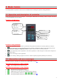
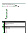
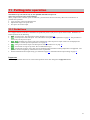
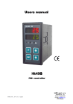
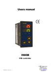
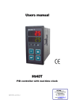
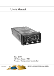
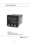
On the front panel board you can see 2 displays, 3 control lights (LED diodes) for indicating a status of outputs. The device
is set and configured via 4 key-buttons.
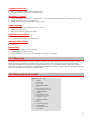
Function of indicators
Upper display:
• Indicates procees value in
Basic mode
• When you set, it shows
parameter value
Lower display:
• Indicates stp value in
Basic mode.
• When you set, it shows the
type of parameter
LED diode „Al“
Indicates the state of alarm output
LED diode „2“
Indicates the state of output 2
LED diode „1“
Indicates the state of output 1
Function of key-buttons
The setting of parameters of the controller is performed via key-board. The function of each key-button is as follows:
•
, key for setting and viewing of parameters of user, operation, configuration and user level. By pressing this key
you confirm the change in configured parameter and the controller comes to another parameter.
•
, key for decreasing a value of parameter. The value of parameter is either the figure or abbreviation composed of
maximum 4 letters.
•
, key for increasing a value of parameter.
•
, key for starting / ending a program. You start or end the requested program by double press of this key.
2.2 Information and error messages
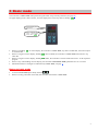
Information and error messages are indicated only in basic mode, see page 5.
Information messages, upper display
•
----
… error of input sensor or input is not set.
Information messages, lower display
•
•
•
•
•
… the indication of the program running.
tdEL … indication of time-delayed start of program.
Gsd … GSD function, process value is beyond the defined soak band.
Aut1 … starting autotunning of PID set 1, Pb1A ,It1A ,dE1A see page 9.
Aut2 … starting autotunning of PID set 2, Pb1b ,It1b ,dE1b see page 9.
ProG
3