1
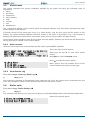
User’s
manualEN
0051-CPD-0225
0051-CPD-0226
0051-CPD-0227
0051-CPD-0228
0051-CPD-0231
0051-CPD-0232
SmartLoop
Analogue fire alarm control panel
User's manual
User’s manual
Copyright
The information contained in this document is the sole property of INIM Electronics s.r.l. No part may be
copied without written authorization from INIM Electronics s.r.l.
All rights reserved
European directive compliance
This Control panel has been designed and developed to the highest standards of quality and performance
implemented by Inim Electronics.
This control panel must be installed in accordance with the instructions described in this manual and in
compliance with the laws in force.
All control panels from the SmartLoop series are EN54-2 and EN54-4 compliant.
All control panels from the SmartLoop series, and all accessory items and special functions have IMQ
Security Systems certification, unless otherwise stated.
2
Copyright
User’s manual
Table of contents
Copyright ........................................................................... 2
European directive compliance .............................................. 2
Table of contents ................................................................. 3
Chapter 1
1.1
1.2
1.3
1.4
1.5
Chapter 2
2.1
2.2
2.3
2.4
2.5
2.6
2.7
2.8
Table of contents
Description of the Control panel ............................................. 4
Manufacturer's name and address 4
Device identification details 4
Documentation supplied 4
Manual details 4
Control panel user interface 5
Using the control panel ........................................................ 8
Note to Security Personnel 8
Danger signaling 8
Fault signaling 9
Informative signaling 9
View Events 10
Dialler calls 10
Operating on the control panel network 11
View detector status 11
3
User’s manual
Chapter 1
Description of the Control panel
1.1
Manufacturer's name and address
INIM Electronics s.r.l.
Via Fosso Antico, Centobuchi
63076 Grottammare (AP) - Italy
Tel: +39 0735 70 50 07
Fax: +39 0735 70 49 12
[email protected] - www.inim.biz
1.2
Device identification details
• Denomination: Fire alarm control panel
• Model: SmartLoop
1.3
Documentation supplied
• User's Manual (this manual)
• Installation Manual
• Programming Manual
1.4
•
•
•
•
4
Manual details
Title: SmartLoop user's manual
Version: 3.01
Month and year: February 2012
Code: DCMUINE0SLOOP
Description of the Control panel
User’s manual
1.5
Control panel user interface
The SmartLoop control panel manages up 15 consoles, the main console is located on the control panel
frontplate (“/G” and “/P” models only), and up to 14 optional consoles (SmartLetUSee/LCD repeaters
connectable to RS485 BUS).
1
2
3
D
J
P
S
E
K
Q
T
F
L
R
U
G
M
H
N
I
O
5
V
4
6
7
A
8
B
9
C
10
11
Figure 1 - Control panel frontplate
1.5.1
Commands
Note:
For further details refer to the programming manual, Chapter 3 - The SmartLoop control panel.
[1]
40 character x 4 line alphanumeric display. Indicates the system status, signals critical events (priority given to
the most serious events), and allows you to navigate through of the main menu and screens.
[2]
STWX
These keys allow you to navigate through menu screens and change the values in the
programming fields.
[3]
Esc
This key allows you to quit an operation and exit the screen without saving, or step back to
higher-level menu options.
This key allows you to confirm an operation and exit a screen, or go to the options of a
lower-level menu.
[4]
Alphanumeric keypad for data entries.
Key 1 allows you to view the specifics of events which provide detailed information (“info”).
If an event relating to a loop device is shown on the display, key 2 will allow you to access the bypass/
unbypass loop device menu.
[5]
Keyswitch: allows level 2 users (Users, Authorized Users) to access the system. Can be used instead of code
entry.
[6]
TEST
This button (active at level 1: no key or code entry required) activates all the console LEDs
in order to allow the operator to check functionality.
[7]
BUZZER
This button (active at level 1) silences the panel beeper.
Description of the Control panel
5
User’s manual
[8]
INVESTIGATE
If this button (active at level 2 only: this level requires key in keyswitch or code entry) is
pressed during active pre-alarm conditions, the system will add the preset investigation
time to the running pre-alarm time (this operation can be done once only).
[9]
SILENCE
This button (active at level 2 only) silences (switches Off) any active outputs with the
silenceable attribute. The silenceable outputs will hold silenced status until a new event
occurs that releases the outputs automatically. The SILENCE button operates as a toggle
switch, therefore, silenced outputs can be unsilenced by pushing the button again.
[10] RESET
This button (active at level 2 only) clears any active events, deletes the memory and
restores standby conditions.
[11] EVACUATE
If this button is pressed during active pre-alarm conditions (level 1), the system will
generate an alarm. If this key is pressed during standby status when the key is in the
keyswitch (level 2), the system will generate an instant alarm.
1.5.2
The LEDs
LED
ON Solid:
ON Blinking:
[A]
INVESTIGATE
Indicates that investigation time has been
requested.
[B]
SILENCE
Indicates that the system has been
silenced.
[C]
RESET
In the event of pre-alarm/alarm, indicates
that reset commands are not allowed.
Reset will be allowed when all outputs have
been silenced and this LED goes Off.
[D]
ALARM
Indicates an alarm condition, that is, an
input point (detector, callpoint, input
module, etc.) set to generate alarms has
detected alarm conditions.
[E]
PRE-ALARM
Indicates a pre-alarm condition, that is, an
input point (detector, callpoint, input
module, etc.) set with a pre-alarm time
has activated.
[F]
DISABLED
Indicates that one or more of the system
components (loop point, zone or output)
have been bypassed.
[G]
TEST
Indicates that one or more components
(points or zones) are undergoing tests.
[H]
NIGHT MODE
Indicates that the panel is operating in
night mode.
[I]
ON
Indicates the control panel is working.
[J]
FAULT
Indicates an active system fault condition.
The display will provide the fault details.
Indicates memory of a cleared fault event.
To view the restored fault condition details,
consult the events log using the main
menu (level 1).
[K]
LOGIC UNIT
Indicates trouble with the panel CPU; the
panel must be sent back immediately to
the manufacturer for repair.
Indicates that the CPU has re-initialized
(due to control panel shutdown or fault
condition). If this occurs, it will be
necessary to check the functionality of the
entire system.
[L]
BATTERY
Indicates that a battery fault has been
detected, the display will provide the fault
details (low battery, battery disconnected).
Indicates that the battery fault has been
cleared. The event details can be viewed
on the display via the main menu (level 1).
6
Description of the Control panel
User’s manual
LED
ON Solid:
ON Blinking:
[M]
EARTH
Indicates voltage dispersion to earth.
Indicates that the dialler fault has been
cleared. The event details can be viewed
on the display via the main menu (level 1).
[N]
FUSE
Indicates a short-circuit on one or more
system devices (e.g. detectors).
Call your installer for immediate
assistance.
Indicates that the dialler fault has been
cleared. The event details can be viewed
on the display via the main menu (level 1).
[O]
MAINS
Indicates electrical mains failure (primary
power source failure).
Indicates that the mains failure has been
cleared. The event details can be viewed
on the display via the main menu (level 1).
[P]
BELLS - ACTIVE
Indicates that the bell output is active.
[Q]
BELLS - FAULT
Indicates that an alarm-signaling device is
not operating properly (e.g. bell out-otorder).
[R]
BELLS DISABLED
Indicates that one or more signaling
outputs have been disabled.
S
DIALLER ACTIVE
Indicates that the SmartLoop/PSTN board
is sending an Alarm or Fault related report
call.
Indicates that the SmartLoop/PSTN board
is sending a technical communication,
monitoring communication, etc.
[T]
DIALLER FAULT
Indicates a dialler fault.
Indicates that the dialler fault has been
cleared. The event details can be viewed
on the display via the main menu (level 1).
[U]
DIALLER DISABLED
Indicates that one or more of the dialler
functions have been bypassed.
[V]
Programmable
LEDs
The cause of activation of this LED can be
defined during the programming phase.
Description of the Control panel
Indicates that the dialler fault has been
cleared. The event details can be viewed
on the display via the main menu (level 1).
7
User’s manual
Chapter 2
Using the control panel
2.1
Note to Security Personnel
Persons responsible for the safety of the building and its occupants (security personnel, etc.) can: put the
control panel in day/night; bypass zones, devices and NAC outputs; clear the call queue; disable alarm and
fault report calls; request system event printouts (refer to the programming manual, Chapter 10 Maintenance operations).
Attention:
2.2
Insert and turn the key. The panel will enable access level 2. The panel will hold level 2
status until the keyswitch is turned Off (key in vertical position).
Danger signaling
In the event of fire hazard, always follow the fire department approved fire drill.
2.2.1
Note to building occupants
All building occupants may view the events log (refer to paragraph 2.5.2 - View Events Log) and the status
of the detectors (refer to paragraph 2.8 - View detector status) and operate remote Repeater (refer to
paragraph 2.7 - Operating on the control panel network).
ALARM LED On
Evacuate the building immediately.
PRE-ALARM LED
On
In the event of real danger, press the EVACUATE button and ensure that all building
occupants evacuate the building immediately. Inform the person/s in charge of the safety
of the building and its occupants immediately. To silence the beeper, press BUZZER.
2.2.2
Note to Security Personnel
To force the panel into alarm status, regardless of its status, press EVACUATE.
8
ALARM/PREALARM/RESET
LEDs On
At least one zone is alarm/pre-alarm status:
- If there is no intervention during a pre-alarm, the panel will generate an alarm
when the pre-set pre-alarm time expires.
- To request INVESTIGATION time, press INVESTIGATE and check the building. The
INVESTIGATION time cannot be refreshed.
- In the event of a false alarm, press SILENCE. The panel beeper and the silenceable
outputs will be silenced until a new event occurs. If the panel is operating in Night
mode, the panel beeper and the silenceable outputs will be unsilenced automatically
after the pre-set time, and the panel will generate pre-alarm status.
- If you wish to re-activate pre-alarm/alarm status after pressing the SILENCE
button, press it again; pre-alarm/alarm signaling and the outputs will re-activate.
- To clear all alarm/fault signaling (active and in memory), press RESET. If the
conditions persist, the panel will generate another alarm.
SILENCE LED On
Indicates that the control panel has been silenced.
RESET LED On
The control panel is in alarm or pre-alarm status. To reset the control panel, you must
press SILENCE before pressing RESET.
Using the control panel
User’s manual
2.3
Fault signaling
2.3.1
Note to building occupants
FAULT LED On or
blinking
2.3.2
Inform the person/s in charge of the safety of the building and its occupants
immediately.
Note to Security Personnel
You must always ensure that faults are dealt with and cleared as soon as possible. However, if you wish to
stop the fault signaling, you can bypass the zone/point/output concerned.
FAULT LED On
Indicates that at least one system fault has been detected. View the fault details on
the display and ensure that it is dealt with and cleared.
On LED Off
Primary and secondary power failure (no mains or battery power). The system is
not working, ensure that power is restored as soon as possible.
CPU LED On
The control panel must be sent back to the manufacturer for repair.
BATTERY LED On
Indicates that the panel batteries are low or inefficient, and must be either charged
or changed.
EARTH LED On
Indicates voltage dispersion to earth. You must find the part of the system
concerned, and that cleared the fault as soon as possible.
FUSE LED On
Indicates short-circuit on one of the AUX or AUX-R terminals.
MAINS LED On
Indicates Mains failure.
BELLS-FAULT LED On
Indicates an alarm-signaling device connection fault (e.g. bell fault) has been
detected.
DIALLER-FAULT LED
On
Indicates a dialler fault or telephone line-down condition.
Blinking on any of the above mentioned LEDs indicates that the respective fault was detected and has since
cleared. In this case, view the fault details on the display via the log in the main menu.
2.4
Informative signaling
Signaling that does not require specific action.
DISABLED LED On
A zone, point or output has been bypassed.
View specifics on display.
TEST LED On
A zone or point is undergoing testing. View specifics on display.
NIGHT MODE LED On
Control panel in Night mode.
Attention:
The panel may have been programmed to generate instant
alarms. During Night mode, SILENCE will be held for the preset silence time only.
ON LED On
The control panel is working.
BELLS-ACTIVE LED
On
The alarm signaling devices are "In Service" (i.e. monitoring the protected area).
BELLS-DISABLED
LED On
Indicates that one or more alarm signaling devices have been bypassed.
DIALLER-ACTIVE
LED On
Indicates that the dialler is sending a control-panel-generated call.
DIALLER-DISABLED
LED On
Indicates that one or more of the dialler functions have been bypassed.
Using the control panel
9
User’s manual
2.5
View Events
The events represent the various conditions signaled by the panel and have the following order of
importance:
1. alarm
2. pre-alarm
3. supervision
4. early-warning
5. fault
6. monitor
7. test
8. disablement
The events that appear on the control panel and repeater displays may have been generated by other
control panels in the network.
If several events of the same type occur (e.g. three faults), only the first event will be shown on the
display. The system displays different real-time events in the order of importance (e.g. if the system is
dealing with three fault events when a pre-alarm event occurs, the pre-alarm will take priority).
Control panel reset operations clear all the events from the display, however, all events are will be saved to
the log and can be viewed on the control panel.
2.5.1
Active events
These are the events that occurred after the last control panel RESET operation.
Event 001of 003 01/01/07 14:34 PM Fri
PRE-ALARM
WAREHOUSE
NORTH EAST SECTOR
CORRIDOR
Point 147
Panel 22 L
Loop n. 4
J1 Main Menu
2 View Log
3 View Pre-alarms
4 View Disablements
2.5.2
This is the first of three events.
Press keys S and T to view other active
events.
Press Esc to view the Events menu:
Press to select the menu option.
Menu options from 3 onwards show all the
events related to the active event type.
View Events Log
From panel: <key>, View Log / Read Log, or:
<key>, 2 / 1
The events are recorded in chronological order. Once the log is full, old events will be overwritten by new
ones. The navigation method is the same as that used for the active events.
2.6
Dialler calls
From panel: <key>, Dialler Settings, or:
<key>, 5
This command will allow you to clear the call queue, and enable/disable Alarm and Fault associated calls.
1 Clear telephone queue
2 Bypass Alarm phone calls
3 Bypass Fault phone calls
10
Select the required option.
Using the control panel
User’s manual
2.7
Operating on the control panel network
From panel: <key>, Remote Console, or:
<key>, 9
This command will allow you to access temporarily one of the control panels in the network from the
console you are working on. During this operating mode, the screens on the display will allow you to
monitor and command the remote control panel.
J001 Control panel 01
002 Control panel 02
003 NOT In Configuration
004 NOT In Configuration
ALARM
001 of 003
FIRE ALARM
SMARTLoop nnn
< Zone Description >
< Device Type >
01/01/11 17:44
Last Alarm Zone yyy Panel zzz
Press S and T to view the control panels in
the network.
Press in correspondence to the remote
control panel you wish to connect to. The
screen of the remote control panel will appear
after a few seconds.
The icon
on the bottom right of the display
confirms that you are communicating with the
selected remote panel, and that any
commands entered at the panel you are
working on will be implemented on the
remote panel you are communicating with.
Press TEST to go back to the local control panel.
Note:
2.8
If the local control panel goes into alarm status while you are working on the remote console, the
remote connection will be interrupted and the screen of the local control panel will be reinstated.
View detector status
From panel: <key>, Check Detectors state, x Loop x, yyy Device, or:
<key>, 2, x, yyy
This option will allow you to view the detector status and some parameter values.
Note:
You must wait several seconds for the control panel to retrieve the detector data.
Refer to the detector instructions for details.
Point
x/yyy <Point Description>
< Device Type> Smoke : 0.004 dB/m
Sensitivity :
0.08dB/m
Contamination : 01%
Using the control panel
Press keys S and T to view the previous and
next detectors.
11
via Fosso Antico Loc. Centobuchi
63076 Monteprandone (AP) ITALY
Tel. +39 0735 705007 _ Fax +39 0735 704912
[email protected] _ www.inim.biz
DCMUINE0SLOOP-R301-20120209