1
3.4 Existing constructions must be in a good state of repair with no evidence of rain penetration or damp. Defects
must be made good prior to installation.
3.5 If present, mould or fungal growth must be treated prior to the application of the product.
3.6 The product must not come into direct contact with flue pipes, chimneys or other heat producing appliances (see
section 8).
3.7 It is essential that construction elements are designed and constructed to incorporate normal precautions against
moisture ingress before the application of the product.
3.8 The product forms a strong bond with clean and dry substrates. This should be taken into account when specifying
the product or anticipating future alterations.
3.9 The product can contribute to the airtightness of the building envelope.
3.10 To satisfy the requirements of NHBC, a vapour control layer (VCL) of a type specified in their Standards must be
applied behind the plasterboard lining in roof and wall applications, and the product must only be applied to a roof
construction incorporating a breathable roof tile underlay.
Pitched roofs, including hybrid roofs tiled or slated to BS 5534 : 2003
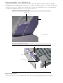
3.11 The product can be applied directly to breathable roof tile underlays, or to the BASF rafter slides and BASF
ventilators which create a ventilation gap between the insulation and the bitumen felt/sarking board. Additionally, the
product is applied to plasterboard, between ceiling joists to create a hybrid roof.
3.12 Care must be taken to ensure the integrity of the roof tile underlay drape when spraying the product (see section 15.4).
3.13 Pitched roofs are defined for the purpose of this Certificate as those roofs having a pitch in excess of 15°.
Concrete ground floor constructions
3.14 The product must not be used where it may come into contact with moisture from the ground.
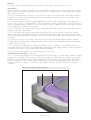
3.15 Ground-supported concrete floors incorporating the product must include a suitable damp-proof membrane (dpm)
laid in accordance with the relevant clauses of CP 102 : 1973, BS 8102 : 1990 and/or BS 8215 : 1991.
3.16 Concrete ground floors incorporating the product must include a dpm or suitable ventilation of the sub-floor as
appropriate.
3.17 The overlay should be:
• a cement-based floor screed, laid in accordance with the relevant clauses of BS 8204-1 : 2003 and/or BS 8204-2 :
2003, and BS 8000-9 : 2003, or
• a concrete slab in accordance with BS 8204-1 : 2003 and BS 8204-2 : 2003.
External masonry walls (insulated dry lining)
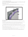
3.18 Insulated dry lining systems require careful detailing during installation around doors and windows to achieve
a satisfactory surface for finishing. In addition, every attempt should be made to minimise the risk of thermal bridging
at reveals and where heavy separating walls are attached to the external wall. New work must be designed to
accommodate the thickness of the dry lining, particularly at reveals, heads, sills and in relation to ceiling height. Where
the dimensions of fixtures are critical (eg bathrooms) these should be checked before installation.
3.19 It is recommended that services which penetrate the dry lining, eg, light switches, power outlets, are kept to a
minimum to limit damage to vapour checks.
External walls (timber-frame)
3.20 Constructions incorporating a masonry outer leaf (such as masonry units and natural stone blocks) should be
in accordance with BS EN 1996-1-1 : 2005, BS EN 1996-1-2 : 2005, BS EN 1996-2 : 2006, BS EN 1996-3 :
2006, BS 5628-3 : 2005 and BS 8000-3 : 2001. The designed residual cavity width should be 50 mm wide.
3.21 It is recommended that services which penetrate the dry lining, eg, light switches, power outlets, are kept to a
minimum to limit damage to vapour checks. In addition, any penetrations should be either enclosed in plasterboard or
stone mineral wool or suitably tested proprietary fire-rated systems in order to preserve the fire resistance of the wall.
3.22 Installation must not be carried out until the moisture content of the timber frame is less than 20%.
4 Practicability of installation
The product must only be installed by contractors trained and approved by the Certificate holder in accordance with
the Certificate holder’s Installation Manual.
5 Thermal performance
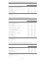
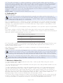
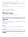
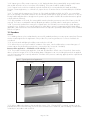
5.1 Calculations of the thermal transmittance (U value) should be carried out in accordance with
BS EN ISO 6946 : 2007 and BRE Report (BR 443 : 2006) Conventions for U-value calculations using the
thermal conductivity values in Table 1. Example U values for pitched roofs, flat roofs, floors and walls are given
in Tables 2 to 4 and typical design roof, floor and wall U values in Tables 5 to 7. Fortuitous air infiltration in hybrid
roofs increases the heat loss from the loft void and should be accounted for by adding a 10% correction factor to the
calculated roof U value (see Table 3).
Page 4 of 16