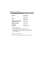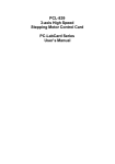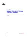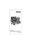
1
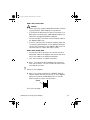
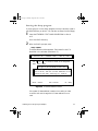
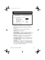
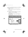
EtherPaC 2000 Front Cover Page 1 Monday, August 26, 1996 11:07 AM
Asanté
EtherPaC 2000+ Series
ISA Ethernet Adapter Cards
Installation Guide
ASANTÉ
inside front cover Page 1 Monday, August 26, 1996 11:10 AM
EtherPaC 2000+ Series
Installation Guide
For ISA Ethernet Adapter Cards
Asanté Technologies, Inc.
821 Fox Lane
San Jose, CA 95131
December 1994
Part Number 06-00112-01 Rev. C
Printed in Taiwan
inside front cover Page 2 Monday, August 26, 1996 11:10 AM
Copyright Notice
Copyright 1994 by Asanté Technologies, Inc.
Printed in Taiwan.
Manual Reorder # 06-00112-01 Rev. C
All rights reserved. No part of this manual, or any associated artwork, software, product design or
design concept, may be copied, reproduced or stored, in whole or in part, in any form or by any
means mechanical, electronic, optical, photocopying, recording or otherwise, including translation
to another language or format, without the express written consent of Asanté Technologies, Inc.
Trademarks
Asanté Technologies, EtherPaC 2000+, and the Connectivity Solution are trademarks of Asanté
Technologies, Inc.
Apple, AppleTalk, EtherTalk, AppleShare, and Macintosh are registered trademarks of Apple
Computer, Inc.
Ethernet is a registered trademark of the Xerox Corporation, Inc.
All brand names and products are trademarks or registered trademarks of their respective holders.
FCC Information
This device complies with part 15 of the FCC Rules. Operation is subject to the following two
conditions: (1) this device may not cause harmful interference and (2) this device must accept any
interference received, including interference that may cause undesired operation.
Operation of this equipment in a residential area is likely to cause interference, in which case, the
user at his own risk and expense will be required to correct the interference.
Asanté Warranty
Asanté Technologies, Inc. warrants that its Asanté EtherPac 2000+ Adapters will be free from defects
in title, materials and manufacturing workmanship for as long as you own the product. If an EtherPac
2000+ Adapter is found to be defective, then, as your sole remedy and as the manufacturer’s only
obligation, Asanté Technologies, Inc. will repair or replace the product (see “Asking for Assistance”
for information on how to contact us). This warranty is exclusive and is limited to Asanté FriendlyNet
Adapters.
This warranty shall not apply to EtherPac 2000+ Adapters that have been subjected to abuse, misuse,
abnormal electrical or environmental conditions, or any condition other than what can be
considered normal use.
Warranty Disclaimers
Asanté Technologies, Inc. makes no other warranties, express, implied or otherwise, regarding
Asanté EtherPaC 2000+ Adapters, and specifically disclaims any warranty for merchantability or
fitness for a particular purpose.
The exclusion of implied warranties is not permitted in some States and the exclusions specified
herein may not apply to you. This warranty provides you with specific legal rights. There may be
other rights that you have which vary from State to State.
Limitation of Liability
The liability of Asanté Technologies, Inc. arising from this warranty and sale shall be limited to a
refund of the purchase price. In no event shall Asanté Technologies, Inc. be liable for costs of
procurement of substitute products or services, or for any lost profits, or for any consequential,
incidental, direct or indirect damages, however caused and on any theory of liability, arising from
this warranty and sale. These limitations shall apply notwithstanding any failure of essential purpose
of any limited remedy.
List of Figures
Figure 2-1
Figure 2-3
Figure 2-4
Figure 2-5
Figure 2-6
Figure 2-7
Figure 2-8
Figure 3-1
Figure 3-2
Removing the cover . . . . . . . . . . . . . . . . . . . . . . . . . . . . . . 2-3
Inserting the adapter in an expansion slot . . . . . . . . . . . . 2-4
The Board Selection Menu . . . . . . . . . . . . . . . . . . . . . . . . . 2-7
The Main Menu . . . . . . . . . . . . . . . . . . . . . . . . . . . . . . . . . 2-8
The default values in the card configuration . . . . . . . . . . . 2-9
The Set Configuration Menu . . . . . . . . . . . . . . . . . . . . . . 2-10
The Set Configuration Menu . . . . . . . . . . . . . . . . . . . . . . 2-12
The Boot ROM socket on the adapter . . . . . . . . . . . . . . . . 3-2
The Set Configuration Menu . . . . . . . . . . . . . . . . . . . . . . . 3-3
iii
Table of Contents
Asking for assistance . . . . . . . . . . . . . . . . . . . . . . . . . . . . . . . . . . .v
Technical support hours . . . . . . . . . . . . . . . . . . . . . . . . . . . . .v
Tell us what you think . . . . . . . . . . . . . . . . . . . . . . . . . . . . . . . . vi
Introducing the EtherPaC 2000+ Adapters
EtherPaC 2000+ Adapter features . . . . . . . . . . . . . . . . . . . . . . .
Easy installation . . . . . . . . . . . . . . . . . . . . . . . . . . . . . . . . . .
Support for 8-bit and 16-bit expansion slots . . . . . . . . . . . .
Diagnostic program . . . . . . . . . . . . . . . . . . . . . . . . . . . . . . .
Remote boot function . . . . . . . . . . . . . . . . . . . . . . . . . . . . .
Support for wide variety of networking software . . . . . . . .
1-2
1-2
1-2
1-2
1-2
1-3
Installing and Configuring the Adapter
Preparing for the installation . . . . . . . . . . . . . . . . . . . . . . . . . . 2-2
Installing an EtherPaC 2000+ Adapter . . . . . . . . . . . . . . . . . . . 2-3
Configuring the EtherPaC 2000+ Adapter. . . . . . . . . . . . . . . . . 2-6
Automatic configuration . . . . . . . . . . . . . . . . . . . . . . . . . . . 2-6
With two or three cards in the PC . . . . . . . . . . . . . . . . . . . 2-6
Starting the Setup program . . . . . . . . . . . . . . . . . . . . . . . . . 2-7
Configuring the adapter automatically . . . . . . . . . . . . . . . . 2-8
Configuring individual parameters on the adapter . . . . . . 2-10
Testing the EtherPaC 2000+ Adapter . . . . . . . . . . . . . . . . 2-12
Booting up the PC from a Server
Installing the EtherPaC Boot ROM . . . . . . . . . . . . . . . . . . . . . . 3-2
Preparing the network server . . . . . . . . . . . . . . . . . . . . . . . . . . 3-4
Preparing the Workstation PC. . . . . . . . . . . . . . . . . . . . . . . . . . 3-5
Specifications
EtherPaC Adapter specifications . . . . . . . . . . . . . . . . . . . . . . . . A-1
Ethernet specifications . . . . . . . . . . . . . . . . . . . . . . . . . . . . . . . A-3
i
Asking for assistance
To contact Asanté Technical Support:
Telephone
(800) 622-7464
(408) 435-0706
Fax
(408) 432-6018
Fax-Backa
(800) 741-8607
(408) 954-8607
Bulletin Board Service (BBS)b
(408) 432-1416
ARA BBS (guest log in)b
(408) 894-0765
Applelink mailc/BBSb
ASANTE.TECH
FTP Archive
b
Internet mail
ftp.asante.com
c
[email protected]
a. Request Master Catalog.
b. Download INDEX.TXT file for catalog of contents.
c. When sending email, please include your full name, US mailing address, phone number, the product name and a description of the problem.
Technical support hours
6:00 AM to 6:00 PM Pacific Standard Time USA, Monday—Friday
v
Tell us what you think
There’s always room for improvement and Asanté Technologies is interested in your comments and suggestions about our product user manuals. If you take the time to make suggestions, we will take the time to
read and consider your suggestions for new manual releases.
Please read through this manual and think about these questions:
•
What do you like best about this manual?
•
What do you think is the least valuable or weakest part of
this manual?
•
What is the most needed improvement you would make to
this manual?
Fax your comments and suggestions to:
Asanté Technical Publications at (408) 894-0363
or
E-mail them through Internet:
[email protected]
vi
Chapter 1
Chapter 2
Introducing the EtherPaC 2000+
Adapters
The Asanté EtherPaC 2000+ Adapters are16-bit ISA Ethernet adapters
that enable you to connect a PC to the Ethernet. You can use the
adapter with an IBM PC, PC XT, PC AT, or their compatibles.
The EtherPaC 2000+ series offers three adapter models. You should
have the adapter that’s appropriate for your network cabling.
EtherPaC 2000+ Adapters Series
Cable Type
Adapter
10BaseT
EtherPaC 2000+ 10T
RJ45 connector with
green link status LED
Thin
EtherPaC 2000+ Thin
BNC connector
10BaseT, Thin
or Thick
EtherPaC 2000+ 3-in-1
RJ45 (with link status
LED), BNC and AUI connectors.
You can install a 16 Kb Boot ROM on each model if you want to load
the operating system on the PC from a server on the network.
1-1
EtherPaC 2000+ Adapter features
The features of the EtherPaC 2000+ Adapter series are
•
•
•
•
•
•
•
Full compliance with IEEE 802.3 Ethernet standards
Easy installation
Support for 8-bit and 16-bit expansion slots
Use of NE2000 drivers
Diagnostic program
Remote boot function for diskless PCs
Support for a wide variety of networking software
Easy installation
You configure the EtherPaC 2000+ Adapter quickly and easily using the
Setup program; you do not need to set any jumpers. The program can
configure your adapter automatically or you can change the default settings if you have a conflict with another card settings.
Support for 8-bit and 16-bit expansion slots
The EtherPaC 2000+ Adapter can be used on an 8-bit or 16-bit expansion slot, enabling you to install the card in any available slot. The system automatically detects which slot the card is using.
Diagnostic program
The diagnostic program included in the software package helps you
identify any problems you may have during the installation.
Remote boot function
The EtherPaC 2000+ Adapter lets you reboot your PC from a remote
server on a NetWare network. For this you need to install a remote boot
ROM (purchased separately from Asanté) on the card. Chapter 3 gives
the installation procedure for this ROM.
1-2
Introducing the EtherPaC 2000+ Adapters
Support for wide variety of networking software
The EtherPaC 2000+ cards support various popular networking software. Appendix A gives a list of the supported software.
1-3
Introducing the EtherPaC 2000+ Adapters
ch 2 Page 1 Monday, August 26, 1996 11:06 AM
Chapter 2
Chapter 2
Installing and Configuring the
Adapter
This chapter provides instructions for installing an EtherPaC 2000+
Adapter.
Before you install the adapter, you need to prepare by:
•
Checking the package contents
•
Becoming aware of the safety rules
To install the adapter, you will:
•
Install the adapter in an empty 8-bit or 16-bit slot
•
Configure the adapter
•
Test the adapter if you encounter promblems
This chapter describes how to prepare and install the adapter.
2-1
ch 2 Page 2 Monday, August 26, 1996 11:06 AM
Preparing for the installation
Check the package contents of your Asanté EtherPaC 2000+ Adapter
package for:
•
The appropriate Asanté EtherPaC 2000+ Adapter for your network cabling. a BNC connector is included with the EtherPaC
2000+ Thin and EtherPac 2000+ 3-in-1.
•
The ETHERPAC AND DRIVERS disk
•
The Installation Guide (this manual)
During the installation you must observe the following safety rules:
2-2
•
Consult your network administrator about the card installation and its effect on the network; other users must be
warned of the possible interruption of network operations.
•
Turn off the PC and all connected peripherals.
•
When you handle the EtherPaC 2000+ Adapter or touch any
component inside the system, use an anti-static strap or
other Electro-Static Discharge (ESD) equipment. If you use
a wrist strap, attach the strap to the chassis after opening
the PC.
•
Handle the EtherPaC 2000+ Adapter by the edges and avoid
touching the connectors and chips.
•
Keep the EtherPaC Adapter in the anti-static bag until you
are ready to install it.
❖
Note: A network interface card is sensitive to static electricity and must be handled very carefully. If you do not handle
the card properly you can damage it and/or you system. The
limited warranty offered by Asanté does not cover any damage you may cause to the card or system.
Installing and Configuring the Adapter
ch 2 Page 3 Monday, August 26, 1996 11:06 AM
Installing an EtherPaC 2000+ Adapter
To install an EtherPaC 2000+ adapter:
1
Turn off the computer and disconnect and remove the
power cable.
2
Remove the computer cover.
screws for
mounting cover
Figure 2-1 Removing the cover
3
Insert the card into an empty 8-bit or 16-bit expansion slot.
For faster performance, use the 16-bit slot.
You do not need to set any jumpers or switches on the
adapter.
∆ Important: With the 3-in-1 EtherPaC 2000+ Adapter,
if you’re using Thick Ethernet cable, set the JP5 trans-
ceiver jumper to AUI. The default is BNC.
NC
JP5
AUI BNC
Figure 2-2 Setting JP5 jumper for AUI on 3-in-1 Adapter
Installing and Configuring the Adapter
2-3
ch 2 Page 4 Monday, August 26, 1996 11:06 AM
4
Gently press the card into the expansion slot until it is fully
seated.
Fasten the holding screw to ground the card to the chassis.
See Figure 2-3.
Figure 2-3 Inserting the adapter in an expansion slot
5
6
Replace the computer’s cover.
Connect the Ethernet cable to the adapter.
Make sure the PC is turned off and the cable’s metal connectors do not touch any metal objects in the computer.
Follow the guidelines given below for your cable type:
With a 10BaseT cabling
Plug the cable’s RJ45 connector into the RJ45 jack on the
adapter and plug the other cable end into a 10BaseT network hub. Be sure the cable between your computer and
the hub is not longer than 328 feet or 100 meters.
2-4
Installing and Configuring the Adapter
ch 2 Page 5 Monday, August 26, 1996 11:06 AM
With a Thin coaxial cable
!
•
•
•
•
Caution!
Check with your network administrator before connecting the EtherPaC 2000+ Adapter to the network.
If the Ethernet cable does not have a T-connector or a
BNC barrel connecting two cable segments, splice the
cable with the appropriate BNC hardware.
Connect the BNC T-connector on the Ethernet cable to
the adapter’s BNC port.
If the PC is at the end of a network segment, keep the
T-connector and terminator on the segment cable and
connect the T-connector to the adapter’s BNC port. The
connector slips on, twists, and locks in place.
With a Thick coaxial cable
•
•
Connect the DB-15 connector on one end of a thick
transceiver cable to the adapter and connect the other
end of the cable to the external transceiver.
Lock the connector or tighten the screws.
❖ Note: Your EtherPac 2000+ Adapter may have more
than one connector. You can connect the card to only
one cable at one time.
7
Power on the computer.
❖ Note: If you have connected to a 10BaseT Ethernet
cable, the green link LED (on the 10T or 3-in-1 Adapter)
lights up to indicate a valid10BaseT link. If the LED
does not light up, check the connection.
Link LED
Go to the next page.
Installing and Configuring the Adapter
2-5
ch 2 Page 6 Monday, August 26, 1996 11:06 AM
Configuring the EtherPaC 2000+ Adapter
You use the Setup program to configure the adapter. The program is
on the ETHERPAC UTILITY AND DRIVERS disk.
You can copy the program to a new DIAG directory on the hard disk
C: drive or you can run it from the floppy.
Automatic configuration
To configure the adapter, you run Auto Configuration and let the Setup
program automatically set the adapter’s parameters to default values.
With two or three cards in the PC
If you have one or two additional cards in the PC with parameters that
conflict with the EtherPaC’s default parameters, you run Set Configuration which lets you change the values in the adapter’s configuration
to non-default values.
2-6
Installing and Configuring the Adapter
ch 2 Page 7 Monday, August 26, 1996 11:06 AM
Starting the Setup program
If you’re going to run the Setup program from the hard disk, create a
new DIAG directory on drive C. You can also run Setup from the floppy.
1
Insert the ETHERPAC UTILITY AND DRIVERS disk in drive A
or B.
Go to the DIAG directory.
2
After the DIAG> prompt, enter:
setup <Enter>
The Board Selection Menu appears. Each board in the PC is
identified in the window (maximum—3).
LAN
Version 2.01
Adapter Setup Program
Release Date:
June 11, 1993
BOARD
Use
Then
or
press
SELECTION
MENU
to select a board to be diagnosed.
Enter.
Board Type: 16: BIT ISA ADAPTER I/O Base: 0300
Board Type: 16: BIT ISA ADAPTER I/O Base: 0280
If only one board appears above and two or more
are in the PC, then the I/O base addresses on two
boards are the same, resulting in a conflict.
Enter = Select
ESC = Cancel
F1 = Help
Figure 2-4 The Board Selection Menu
If the same I/O base address is used on two cards, you have
a conflict and must change the I/O base address on one
card.
Installing and Configuring the Adapter
2-7
ch 2 Page 8 Monday, August 26, 1996 11:06 AM
Configuring the adapter automatically
1
Select the Asanté EtherPaC 2000+ Adapter in the Board
Selection Menu and press <Enter>.
The Main Menu appears with Auto Configuration selected:
LAN
Version 2.01
Adapter Setup
Release Date:
MAIN
Program
June 11, 1993
MENU
Use
or
to select one of the following.
Then press Enter.
Auto
Set
Test
Exit
Enter = Select
Configuration
Configuration
the Adapter
to Operating System
ESC = Cancel
F1 = Help
Figure 2-5 The Main Menu
2
Press <Enter>.
The Setup program automatically configures the EtherPaC
adapter.
The Set Configuration Menu appears displaying the board’s
set default values as shown in Figure 2-6.
2-8
Installing and Configuring the Adapter
ch 2 Page 9 Monday, August 26, 1996 11:06 AM
LAN
Version 2.01
SET
Adapter Setup
Release Date:
Program
June 11, 1993
CONFIGURATION
LAN Type: Ethernet
Network Address:
00
00
MENU
E6
Slot:
16-BIT
C0 FD 7D
The card configuration is as follows:
Adapter Mode
Base I/O Address
IRQ Interrupt
Transceiver
Boot ROM Base Address
Turbo Mode
:
:
:
:
:
:
NE2000
0300
3
T.P.
D8000
DISABLE
Press any key to continue.
Figure 2-6 The default values in the card configuration
The supported settings for each parameter are listed in
Appendix A.
The board parameters and their default value are
Adapter Mode—Selects NE2000.
I/O Base Address—7 addresses are available ranging from
0240 to 0360; 300H is the default setting. IRQ Interrupt—8
values are available values for a unique IRQ channel.
Transceiver—configures the unit to the correct cable type.
The default setting depends on your adapter type.
Boot ROM Base Address—8 options are available ranging
from C0000H to DFFFFH, excluding the Disable selection.
The default is Disable.
Turbo Mode—set to Enabled only if the adapter fails when
the NE2000 mode is used due to incompatibility between
the PC’s AT-bus and the adapter’s I/O Channel Ready signal
(I/O CHRDY). The default is Disabled.
Installing and Configuring the Adapter
2-9
ch 2 Page 10 Monday, August 26, 1996 11:06 AM
Configuring individual parameters on the adapter
1
Select Set Configuration from the Main Menu and press
<Enter>.
The Set Configuration Menu appears with the Adapter Mode
value highlighted.
2
To change a parameter value, first select it by using the UP
or DOWN arrow key, then press <Enter>.
A pop-up menu appears showing the available values for the
selected parameter.
The example in Figure 2-7 shows the options available for
the Base I/O address.
LAN Adapter Setup Program
Release Date:
June 11, 1993
Version 2.01
SET
CONFIGURATION
LAN Type: Ethernet
Network Address:
00
00
MENU
E6
Slot:
C0 FD
16-BIT
7D
Use
or
to select one of the following.
0240
Then press Enter.
0280
Adapter Mode
: NE2000
0300
Base I/O Address
: 0300
02C0
IRQ
Interrupt
: 3
0320
Transceiver
: T.P.
0340
Boot ROM Base Address : D8000
0360
Turbo Mode
: DISABLE
Enter = Select
ESC = Cancel
F1 = Help
F3 = Save
Figure 2-7 The Set Configuration Menu
2-10
Installing and Configuring the Adapter
ch 2 Page 11 Monday, August 26, 1996 11:06 AM
3
Set the Turbo Mode to Enabled only if the adapter fails when
using the NE2000 mode due to an incompatibility between
the PC’s AT-bus and the adapter’s I/O Channel Ready signal
(I/O CHRDY).
This system message appears:
*** CAUTION ***
The Turbo Mode should be set to DISABLE (factory default
setting) for normal operation.You may ENABLE it only if the
adapter fails the Memory or RAM Test. Improper use of the
Turbo Mode may result in unpredictable system operation.
4
5
To save your changes, press <F3> and to return to the Main
Menu, press <ESC>.
To exit the Setup program, select Exit to Operating System.
Installing and Configuring the Adapter
2-11
ch 2 Page 12 Monday, August 26, 1996 11:06 AM
Testing the EtherPaC 2000+ Adapter
The Setup program provides a diagnostic program for testing the EtherPaC 2000+ Adapter. The best way to run the test is to run it simultaneously on two or more PCs on the network. You can run the test on
a single PC.
To test one or more adapters:
1
Select Test the Adapter in the Main Menu of Setup.
The program runs a number of tests and indicates the
results with PASS or FAIL in the Test the Adapter Menu.
When a test fails, an error is reported and suggested action
for solving the problem is given.
LAN
Version 2.01
Adapter Setup Program
Release Date:
June 11, 1993
TEST
THE
LAN Type: Ethernet
Network Address:
Use
Then
or
press
ADAPTER
00
00
Node ID:
:
:
E6
Slot:
16-BIT
C0 FD 7D
to select one of the following.
Enter.
Configuration
Test
I/O Test
ID Test
RAM Test
Internal Loopback Test
External Loopback Test
Interrupt Test
Network Function Test
Tx Count
Time
MENU
:
:
:
:
:
:
:
:
PASS
PASS
PASS
PASS
PASS
PASS
PASS
PASS
[00 00 E8 C0
FD 8D]
0 Packets
0 Seconds
Press <F1> to Reset Counter.
<F2> to Toggle ON/OFF,
<ESC> to Exit
Figure 2-8 The Set Configuration Menu
2-12
Installing and Configuring the Adapter
ch 2 Page 13 Monday, August 26, 1996 11:06 AM
Also displayed are the number of transmit (TX Count) and
receive (RX Count) packets over a transmission period
(Time). The adapter’s performance, in bytes per second
(BPS), is calculated automatically.
The diagnostics tests are
Configuration Test—identifies the host PC’s type.
I/O Test—checks the accessibility of the I/O port.
ID Test—verifies the adapter’s ID.
RAM Test—checks the on-board RAM’s condition.
Internal Loopback Test—checks the controller.
External Loopback Test—checks the network link.
Interrupt Test—checks the Interrupt Generation.
Network Function Test—checks the adapter’s ability to receive
and transmit network packets.
2
To select an option in the menu, press the UP or DOWN
arrow key and then press <Enter>.
To reset all counters to zero, press <F1>.
To turn packet transmission on or off, use the <F2> key as a
toggle switch.
To exit the diagnostics program and return to the Main
Menu, press <ESC>.
To exit Setup, select Exit to Operating System.
Installing and Configuring the Adapter
2-13
Chapter 3
Chapter 2
Booting up the PC from a Server
You may want to boot up your PC from a remote server on the network. Or you may have a PC without a boot diskette or a disk drive
and need to boot it up from a remote server.
In each case, to boot up the PC, you need to:
•
Install an Asanté EtherPaC remote Boot ROM on the EtherPaC 2000+ Adapter
•
Have Novell’s Netware software on the network
•
Prepare the PC and the server
•
Boot up the PC by rebooting the server
The 16 Kb Asanté ISA Boot ROM allows you to load the operating system to a PC over the network.
This chapter provides instructions for each of the above steps
required.
3-1
Installing the EtherPaC Boot ROM
You install the Boot ROM in the ROM socket of the Asanté EtherPaC
Adapter.
1
If the EtherPaC 2000+ is installed in the PC and connected
to the network, turn off the PC and disconnect and remove
the adapter.
❖ Note: Follow the safety instructions described on
page 2-2.
2
3
4
Take the Boot ROM out of its protective packaging.
Check all pins on the ROM to make sure none are bent.
Locate the socket for the Boot ROM on the adapter.
Align the Boot ROM’s notch and pins with the socket’s
notch and pins and gently press the ROM into the socket.
See Figure 3-1.
Be careful not to bend the pins.
notch
Boot ROM
socket
Figure 3-1 The Boot ROM socket on the adapter
3-2
Booting up the PC from a Server
5
6
Install the EtherPaC 2000+ Adapter in the PC and turn on
the PC.
To enable the PC’s remote boot function:
Start the Setup program. (See "Starting the Setup program"
on page 2-7)
In the Set Configuration Menu, select the appropriate
address from the Boot ROM base address options.
Press <F3> to save the configuration.
LAN
Version 2.01
SET
Adapter Setup Program
Releas e Date:
June 11, 1993
CONFIGURATION
MENU
LAN Type: Ethernet
Network Address:
00
00
E6
The
is
as
follows:
card
configuration
Adapter Mode
Base I/O Address
IRQ Interrupt
Transceiver
Boot ROM Base Address
Turbo Mode
Press
any
key
to
:
:
:
:
:
:
Slot:
16-BIT
C0 FD 7D
NE2000
0300
3
T.P.
D8000
DISABLE
continue.
Figure 3-2 The Set Configuration Menu
7
The system restarts after you save the configuration.
Booting up the PC from a Server
3-3
Preparing the network server
1
Create an AUTOEXEC.NCF file on the server.
The file below is an example of an AUTOEXEC.NCF file.
file server name
FILE SERVER NAME SERVER_GREEN
network number
server interrupt
IPX INTERNAL NET 10
LOAD NE2000 PORT=300 INT=3 FRAME=ETHERNET_802.3 NAME=DOT3
LOAD NE2000 PORT=300 INT=3 FRAME=ETHERNET_802.3 NAME=DOT2
LOAD RPL
BIND IPX TO DOT3 NET=100
network number
BIND IPX TO DOT2 NET=200
BIND RPL TO DOT2
port on NE2000
The values in this file are examples only. Use the values that
apply to your network.
2
The \LOGIN directory must have:
NET$DOS.SYS
generated by DOSGEN.EXE,
“patched” by RPLFIX.EXE
RBOOT.RPL
Novell file
The \SYSTEM directory must have:
3-4
RPL.NLM
Novell Netware loadable module for
remote program load
DOSGEN.EXE
used to generate NET$DOS.SYS
RPLFIX.EXE
used to “patch” NET$DOS.SYS
Booting up the PC from a Server
Preparing the Workstation PC
1
Create a DOS IMAGE bootable floppy disk:
C:/>format a:/s
2
Create the following files on the DOS IMAGE floppy disk:
CONFIG.SYS file:
FILES=20
BUFFERS=10
DEVICE=SETVER.EXE
AUTOEXEC.BAT file:
LSL
NWMLID
IPXODI
NETX
NET.CFG file containing:
LINK DRIVER NWMLID
FRAME ETHERNET_802.3
FRAME ETHERNET_802.2
PROTOCOL IPX 0 ETHERNET_802.3
3
Copy the following files to the DOS IMAGE floppy disk:
LSL.COM
NWMLID.COM
IPXODI.COM
NETX.EXE
SETVER.EXE
Booting up the PC from a Server
3-5
4
Create the NET$DOS.SYS image file:
Login as SUPERVISOR on the server.
In the LOGIN directory, type:
\system\dosgen a:
This creates the NET$DOS.SYS file.
Enter:
\system\rplflix NET$DOS.SYS
5
3-6
Reboot the server and the PC.
The PC should execute the remote program automatically
from its boot ROM.
Booting up the PC from a Server
a. Refer to the READ.ME file located in the subdirectory of your selected driver for installation instructions.
The settings supported for the adapter are
Adapter Mode
I/O base address
IRQ
Transceiver
Boot ROM address
Turbo Mode
NE2000
0240, 0300, 0280, 02C0, 0320, 0340, 0360
3, 4, 5, 9, 10, 11, 12, 15
3-in-1-—TP, BNC, AUI: 2-in-1—TP, BNC;
10BaseT—TP; Thin—BNC
For 3-in-1, 2-in1, 10BaseT, default is TP;
for Thin, default is Thin
C0000, C4000, C8000, CC000, D0000, D4000, D8000,
DC000, Disable (default)
Enable, Disable (default)
The power requirements are
3-in-1 Adapter
UTP Transceiver: 0.49A
(Stand-by), 0.55A (Transmit)
BNC Transceiver: 0.38A
(Stand-by), 0.49A (Transmit)
AUI External Transceiver:
+12V/0.5A (Max.)
A-2
10T
Thin
0.25A
(Stand-by),
0.33A
(Transmit)
0.38A
(Stand-by),
0.47A
(Transmit)
Specifications
Ethernet specifications
The Ethernet specifications are given below.
Parameter
10Base2
10Base5
10BaseT
Cable
Thin
Thick
UTP
Impedance
50 ohms
50 ohms
100 ohms
Connector on cable
BNC
DB-15
RJ45
Data transfer rate
10 Mbps
10 Mbps
10 Mbps
Topology
Bus
Bus
Star
Segment length
(maximum)
185 meters
500 meters
100 meters
Distance between nodes
(minimum)
0.5 meter
1 meter
n/a
Nodes per segment
(maximum)
30
500
n/a
Specifications
A-3
EtherPaC Back Cover Page 2 Monday, August 26, 1996 11:08 AM
Asanté Technologies, Inc.
821 Fox Lane
San Jose, CA 95131
December1994
Part Number 06-00112-01 Rev. C
Printed in Taiwan