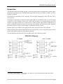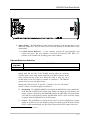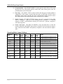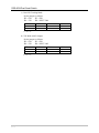
1
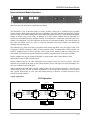
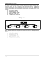
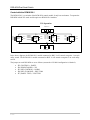
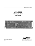
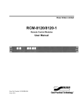
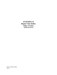
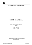
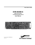
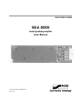
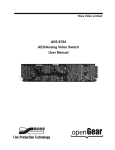
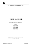
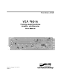
DSS-8024 Dual Serial Switch USER MANUAL 8024-DSS-02 Issue 2 DSS-8024 • Dual Serial Switch – User Manual • • • Ross Part Number: 8024-DSS-02 Document Issue: 2 Printing Date: March 15, 2000. Printed in Canada. The information contained in this guide is subject to change without notice or obligation. Copyright © 2000 Ross Video Limited. All rights reserved. Contents of this publication may not be reproduced in any form without the written permission of Ross Video Limited. Reproduction or reverse engineering of copyrighted software is prohibited. Notice The material in this guide is furnished for informational use only. It is subject to change without notice and should not be construed as commitment by Ross Video Limited. Ross Video Limited assumes no responsibility or liability for errors or inaccuracies that may appear in this manual. Trademarks • • • is a registered trademark of Ross Video Limited. and RossGear are registered trademarks of Ross ROSS Ross, ROSS, Video Limited. All other product names and any registered and unregistered trademarks mentioned in this guide are used for identification purposes only and remain the exclusive property of their respective owners. Company Address Ross Video Limited 8 John Street Iroquois, Ontario, K0E 1K0 Canada Ross Video Incorporated P.O. Box 880 Ogdensburg, New York USA 13669-0880 General Business Office: (+1) 613 • 652 • 4886 Fax: (+1) 613 • 652 • 4425 Customer Service: (+1) 613 • 652 • 4886 E-mail (Customer Support): [email protected] E-mail (General Information): [email protected] Website: http://www.rossvideo.com After hours emergency: (+1) 613 • 652 • 4886, ext. 333 DSS-8024 Dual Serial Switch Introduction The DSS-8024 Dual Serial Switch provides a convenient and economical solution when systems require switching of serial digital video. The DSS-8024 supports data rates up to 360 Mb/s (143Mb/s, 177 Mb/s, 270 Mb/s, 360 Mb/s). Each card has 4 inputs and two 4X1 crosspoints. The card can be configured for 4X2, 4X1, dual 2X1 or 2X1 operation. Each switch is controlled by an optional control module (RMC-8120 OR RMC-8120-1) or by GPI contact or logic level.‡ All switching is done in the vertical interval, timed to an external analog color black reference. Ross digital frames have a connection for a master reference input, which is distributed to all cards. An additional reference connector for each card is provided for use with Leitch* frames. When the Ross frame reference is used, a second output is available from the first switch. Indicator lights are provided for input signal presence and to show the status of each crosspoint. When used with option control module (RCM-8120 or RCM-8120-1), the last crosspoint selected will be saved to non-volatile memory for power failure protection. The DSS-8024 Dual Serial Switch is also compatible with Leitch* 6800-series frames. 8024 Block Diagram ‡ * The Terms “Control Module”, “Control Panel”, and “Panel” are used interchangeably throughout this manual. Leitch is a trademark of Leitch Technology Corporation. 1-2 DSS-8024 Dual Serial Switch Features • • • • • • • • • • • • Switches all standards of serial digital video (to 360 Mb/s) 4 inputs 2 outputs (1 per switch) Can be configured as a 4X2 or dual 2X1 Controllable by the RMC-8120 module or GPIs When controlled by remote module, last crosspoint selected is saved to non-volatile RAM. All switching done in the vertical interval (external analog REF) Economical cost per switch Indicators for input signal presence Indicators for status of each crosspoint Fits Ross and Leitch* digital frames 5 year transferable warranty Installation To install: 1) Cables - Connect the input and output cables. Each input is internally terminated in 75 ohms. The BNC connectors on the rear of the frame are marked for distribution amplifiers having eight outputs. However, the DSS-8024 has four inputs, one REF input, two outputs, and two GPI/Remote Module inputs. It is not necessary to terminate unused outputs. Cable Connections Diagram IN 1 IN IN 2 2 1 GPI/PNL 1 4 OUT 1A OUT 1B/REF** 3 GPI/PNL 2 6 5 IN 3 8 10 7 OUT 2 IN 4 ** Note: Used to connect a color black input. Connector 3 is only used with Leitch* frames. Ross Frames use a master frame REF BNC connector that feeds the reference signal to all modules in the frame. * Leitch is a trademark of Leitch Technology Corporation 1-3 DSS-8024 Dual Serial Switch 2) Jumper Setting - The DSS-8024 has many modes of operation. Take the time now to learn what each jumper does. This will allow you to tailor the function of the DSS-8024 to your requirements. a) Vertical Interval Reference - A sync separator provides the microcontroller with vertical rate pulses. The sync separator is fed from JP4 and JP5 (EXT REF). If a reference is not available, the switching point will be random. External Reference Selection JP4 and JP5 POSITION FRAME O/P 3 FUNCTION The external reference comes from the frame reference. The external reference comes from output 3. Putting both JP4 and JP5 in the FRAME position takes the switching reference from a color black signal connected to the REF connector on the frame, located near the power cord. When this mode is used, out 1B, a second output of the first switch is available on connector 3. The FRAME position is for use only with Ross Frames. Putting both JP10 and JP11 in the O/P 3 position is for use with Leitch* frames. Connect a color black signal to connector 3. * b) Board Mode – JP1 (BOARD MODE) is used when the DSS-8024 is being controlled by an RCM-8120 or RCM-8120-1 module. One module can control up to 10 switches (one master, 9 slaves). With JP1 in the MASTER position, the DSS-8024 will be the master card. With JP1 in the SLAVE position, the DSS-8024 will be a slave card. This jumper is ignored when the DSS-8024 is set for GPI control. c) Control – JP2 (CONTROL) is used to tell the card if it will be controlled by a remote module or by GPI. Set it to the PANEL position for control by an RCM-8120 or RCM8120-1 remote control module. Set JP2 to the GPI position for GPI control of the card. Leitch is a trademark of Leitch Technology Corporation. 1-4 DSS-8024 Dual Serial Switch d) Crosspoint Mode – JP6 (XPOINT MODE) is used to put the card in 4X1 or 2X1 mode. Moving JP6 to the 4X1 position puts the card in 4X1 mode. Moving JP6 to the 2X1 position puts the card in 2X1 mode. e) Panel Type – JP7 (PANEL TYPE) is used to tell the card what type of control module is connected to it. This jumper is ignored when the card is in GPI mode. Put JP7 in the 4 BUTTON position when connecting the card to an RCM-8120 module. Put JP7 in the 2 BUTTON position when connecting the card to an RCM-8120-1 module. f) Switch 2 Control – JP3 (SW2 CONTROL) allows you to slave crosspoint 2 on the DSS8024 to crosspoint 1. With JP3 in the NORM position, crosspoint 2 is controlled normally via BNC 6 (GPI/PANEL2). Moving JP3 to the FW 1 position, crosspoint 2 will track crosspoint 1. g) Switch 2 2X1 mode – JP8 (SW2 2X1 MODE) is only used when JP6 is in the 2X1 position. With JP8 in the INPUT 3&4 position, crosspoint 2 will select between inputs 3 and 4. With JP8 in the INPUT 1&2 position, crosspoint 2 will select between inputs 1 and 2. Operating Mode Jumper Settings OPERATING MODE JP 2 CONTROL JP 6 XPOINT MODE JP 3 SW2 CONTROL JP 8 SW2 2X1 MODE JP 7 PANEL TYPE NOTES DUAL 2X1 GPI GPI 2X1 NORM INPUT 3&4 N/A GPI 1 (BNC 4) controls OUT 1 (selects IN 1 or IN 2) GPI 2 (BNC 6) controls OUT 2 (selects IN 3 or IN 4) 2X2 GPI GPI 2X1 NORM INPUT 1&2 N/A GPI 1 (BNC 4) controls OUT 1 (selects IN 1 or IN 2) GPI 2 (BNC 6) controls OUT 2 (selects IN 1 or IN 2) GPI 2X1 FW 1 INPUT 3&4 N/A GPI 1 (BNC 4) controls OUT1 (selects IN 1 or IN 2) AND OUT 2 (selects IN 3 or IN 4) 2X1 GPI WITH 2 OUTPUTS GPI 2X1 FW 1 INPUT 1&2 N/A GPI 1 (BNC 4) controls OUT 1 and OUT 2 (both outputs set to the same input, either IN 1 or IN 2) 4X1 GPI GPI 4X1 N/A N/A N/A GPI’s are binary encoded, OUT 2 tracks OUT 1. 4X2 PANEL PNL 4X1 NORM N/A 4 BUTTON Requires 2 RCM-8120 modules. 4X1 PANEL PNL 4X1 FW 1 N/A 4 BUTTON Requires 1 RCM-8120 module, OUT 2 tracks OUT 1. PNL 2X1 NORM AS REQUIRED 4 BUTTON PNL 2X1 NORM AS REQUIRED 2 BUTTON PNL 2X1 FW 1 AS REQUIRED 2 BUTTON DUAL 2X1 TRACKING GPI DUAL 2X1 PANEL ONE DUAL 2X1 PANELS TWO 2X1 PANEL WITH 2 OUTPUTS 1-5 Requires 1 RCM-8120 module. OUT 2 can configured via JP8 to select between IN 1&2 OR 3&4. Requires 2 RCM-8120-1 modules. OUT 2 can configured via JP8 to select between IN 1&2 OR 3&4. be IN be IN Requires 1 RCM-8120-1 module. OUT 2 can be configured via JP8 to select between In 1&2 OR IN 3&4. DSS-8024 Dual Serial Switch Notes on GPI Operation In GPI mode, the card can work two ways. The first way is as a dual 2X1 switch. The second way is as a 4X1 switch. There are two GPI input BNC connections. The first input of each 2X1 switch is selected unless the GPI input is grounded. A ground or low logic level will cause the second input to be selected. In 4X1 mode, the GPIs are binary encoded. GPI shields can be tied together. 3) 4X1 GPI Operation - When using the card in 4X1 GPI mode, the GPIs are binary encoded. Set the jumpers as follows: JP2 = GPI JP6 = 2X1 GPI 1 Open Short JP3 = NORM JP8 = INPUT 3&4 OUT 1 IN 1 IN 2 GPI 2 Open Open OUT 2 IN 1 IN 2 4) 2X1 GPI Operation - In 2X1 mode, there are 4 modes of operation: Dual 2X1, 2X2, Dual 2X1 Tracking, and 2X1 with 2 outputs. These modes are described below. For GPI control in 2X1 modes, the RCS-8120 is available from Ross. This optional module has two dual push button switches on it. It can control both GPIs on the DSS-8024. The RCS-8120 fits into the Ross MRP-8120 Control Panel (which can hold a total of 5 modules), or is mounted in desk with the optional in desk mounting adapter DCA-8120. a) Dual 2X1 Mode: Set the jumpers as follows: JP2 = GPI JP3 = NORM JP6 = 2X1 JP8 = INPUT 3&4 GPI 1 Open Short OUT 1 IN 1 IN 2 GPI 2 Open Short OUT 2 IN 3 IN 4 GPI 2 Open Short OUT 2 IN 1 IN 2 b) 2X2 Mode: Set jumpers as follows: JP2 = GPI JP3 = NORM JP6 = 2X1 JP8 = INPUT 1&2 GPI 1 Open Short OUT 1 IN 1 IN 2 1-6 DSS-8024 Dual Serial Switch c) Dual 2X1 Tracking Mode: Set the jumpers as follows: JP2 = GPI JP3 = FW 1 JP6 = 2X1 JP8 = INPUT 3&4 GPI 1 Open Short OUT 1 IN 1 IN 2 GPI 2 X X OUT 2 IN 3 IN 4 X = don’t care d) 2X1 Mode with 2 Outputs: Set the jumpers as follows: JP2 = GPI JP3 = FW 1 JP6 = 2X1 JP8 = INPUT 1&2 GPI 1 Open Short X = don’t care 1-7 OUT 1 IN 1 IN 2 GPI 2 X X OUT 2 IN 1 IN 2 DSS-8024 Dual Serial Switch Notes on Remote Module Operation: MRP-8120 panel with RCM-8120-1 and RCM-8120 installed. The DSS-8024 is part of the Ross family of utility switches, which can be controlled by the optional control modules. Each control module has four push buttons with LED indicators and insertable legends. Up to 10 cards (AVS-8064 or DSS-8024) can be controlled simultaneously by a single RCM-8120 control module (1 master card, 9 slave cards). In addition, up to three control modules may be connected to a control bus. In installations where multiple modules are connected to a control bus, selection of the active module is accomplished via a GPI connection on the back of each control module. Care must be taken to have only one module active at a time to avoid bus contention. Non-active modules will indicate the currently selected crosspoint. The control bus is a single coax cable. It originates at the master card (BNC 4 for cross point 1, BNC 6 for Crosspoint 2). NOTE: crosspoint 1 (BNC 4) and crosspoint 2 (BNC 6) cannot share a control module. All female T connectors may be used to split the coax at each card or module to loop the control bus to the next module. The control bus provides both power and data communications to the remote modules. Remote modules may also be connected together via audio/control cable such as Belden 1503A audio/control cable (22 AWG shielded pair). Remote modules may also be GPI controlled (closed contact or logic low (level or pulse)). Four GPI terminals are provided on the back of each control module, one for each input. For more information, see the User’s Manual for the RCM-8120. When controlling the DSS-8024 with the control module, the last selected crosspoint is saved to nonvolatile memory. This is useful in mobile installations, as the crosspoints do not have to be re-selected after a power down/power up cycle. The non-volatile memory is rated for 1 million write/erase cycles with 40 years data retention. Typical Applications: 4X2 Operation RCM-8120 Vid 1 Vid 2 Vid 3 Vid 4 AVS-8064 Master BNC 6 BNC 4 BNC 4 BNC 4 OUT 1 OUT 2 AES/EBU 1 AES/EBU 2 AES/EBU 3 AES/EBU 4 AVS-8064 Slave OUT 1 OUT 2 Dig. Vid 1 Dig. Vid 2 Dig. Vid 3 Dig. Vid 4 DSS-8024 Slave OUT 1 OUT 2 Vid 1 Vid 2 Vid 3 Vid 4 AVS-8064 OUT 1 OUT 2 BNC 6 BNC 6 RCM-8120 1-8 DSS-8024 Dual Serial Switch The diagram (on the previous page) shows 4 of the Ross family of utility switches connected to RMC8120 control modules. The cards are configured for 4X2 remote module operation. The RCM-8120 connected to BNC 4 on each card will simultaneously switch crosspoint 1 on each card. The RCM-8120 connected to BNC 6 on each card will simultaneously switch crosspoint 2 on each card. Jumpers are set as follows: • • • • • JP2 (CONTROL) = PANEL JP6 (XPOINT MODE) = 4X1 JP3 (SW2 CONTROL) = NORM JP8 (SW2 2X1 MODE) = N/A JP7 (PANEL TYPE) = 4 BUTTON 4X1 Operation RCM-8120 Vid 1 Vid 2 Vid 3 Vid 4 AVS-8064 Master BNC 4 BNC 4 BNC 4 OUT 1 OUT 2 AES/EBU 1 AES/EBU 2 AES/EBU 3 AES/EBU 4 AVS-8064 Slave OUT 1 OUT 2 Dig. Vid 1 Dig. Vid 2 Dig. Vid 3 Dig. Vid 4 DSS-8024 Slave OUT 1 OUT 2 Vid 1 Vid 2 Vid 3 Vid 4 AVS-8064 OUT 1 OUT 2 In 4X1 operation, switch 2 on each card is set to follow switch 1 (via JP6 SW2 CONTROL being put into the FW 1 position). Therefore, both crosspoints on each card select the same input. The jumpers are set as follows: • • • • • 1-9 JP2 (CONTROL) = PANEL JP6 (XPOINT MODE) = 4X1 JP3 (SW2 CONTROL) = FW 1 JP8 (SW2 2X1 MODE) = N/A JP7 (PANEL TYPE) = 4 BUTTON DSS-8024 Dual Serial Switch 2X1 Operation Control with the RMC-8120 module: The RCM-8120 has four buttons. When the DSS-8024 is configured for 2X1 operation with this module, the two left buttons control output 1 and the two right buttons control output 2. 2X1 Operation These 2 Buttons Control OUT 2 These 2 Buttons Control OUT 1 AVS-8064 Master BNC 4 BNC 4 BNC 4 Vid 1 Vid 2 Vid 3 Vid 4 OUT 1 OUT 2 AES/EBU 1 AES/EBU 2 AES/EBU 3 AES/EBU 4 AVS-8064 Slave OUT 1 OUT 2 Dig. Vid 1 Dig. Vid 2 Dig. Vid 3 Dig. Vid 4 DSS-8024 Slave OUT 1 OUT 2 Vid 1 Vid 2 Vid 3 Vid 4 AVS-8064 OUT 1 OUT 2 In the above diagram, we will assume that the AVS-8064 configuration is the same as the DSS-8024, and that the DSS-8024 is configured as follows: • • • • • JP2 (CONTROL) = PANEL JP6 (XPOINT MODE) = 2X1 JP3 (SW2 CONTROL) = NORM JP8 (SW2 2X1 MODE) = INPUT 3&4 JP7 (PANEL TYPE) = 4 BUTTON The two left buttons on the RCM-8120 control crosspoint 1 on each card. They will select IN 1 or IN 2 for OUT 1. The two right buttons will control crosspoint 2 on each card. They will select IN 3 or IN 4 for OUT 2. Moving JP7 (SW2 2X1 MODE) to the INPUT 1&2 position will force crosspoint 2 to select either IN 1 or IN 2. This would provide independent control of the same 2 input signal (i.e. 2X2). 1-10 DSS-8024 Dual Serial Switch Control with the RCM-8120-1 The RCM-8120-1 is a variation of the RCM-8120 control module. It only has two buttons. To operate the DSS-8024 in dual 2X1 mode would require two RCM-8120-1 modules. 2X1 Operation RCM-8120-1 Vid 1 Vid 2 Vid 3 Vid 4 AVS-8064 Master BNC 6 BNC 4 BNC 4 BNC 4 OUT 1 OUT 2 AES/EBU 1 AES/EBU 2 AES/EBU 3 AES/EBU 4 AVS-8064 Slave OUT 1 OUT 2 Dig. Vid 1 Dig. Vid 2 Dig. Vid 3 Dig. Vid 4 DSS-8024 Slave OUT 1 OUT 2 Vid 1 Vid 2 Vid 3 Vid 4 AVS-8064 OUT 1 OUT 2 BNC 6 BNC 6 RCM-8120-1 In the above diagram, the RCM-8120-1 module connected to BNC 4 will control crosspoint 1 on each utility switch. The RCM-8120-1 module connected to BNC 6 will control crosspoint 2 on each utility switch. The jumpers on each DSS-8024 are set as follows (assume the AVS-8064 configuration is identical): • • • • • 1-11 JP2 (CONTROL) = PANEL JP6 (XPOINT MODE) = 2X1 JP3 (SW2 CONTROL) = NORM JP8 (SW2 2X1 MODE) = INPUT 3&4 JP7 (PANEL TYPE) = 2 BUTTON DSS-8024 Dual Serial Switch Notes on connecting multiple remote modules to a control bus: Up to three control modules can be connected to a control bus. However, to avoid bus contention, only one module may be active at a time. Active modules have a red LED on the front of the panel lit up. Nonactive modules will continue to indicate the currently selected crosspoint. Pressing buttons on a nonactive module will have no effect on the utility switch connected to the module. To select which module is active, a GPI (closed contact or logic level) must short the module GPI. On the back of each module is a 3-pin connector for the GPI. Shorting pins 1 and 2 together, or bringing pin 1 to a low logic level, will enable the module. In installations where two modules are connected to a control bus, the RCS-8120 may be connected to the two remote modules to select which module is active. The RCS-8120 has two dual push button switches, so one RCS-8120 can control four RCM-8120 modules. Multiple Control Modules ½ RCS-8120 RCM-8120 RCM-8120 OUT 1 AVS-8064 Master BNC 4 BNC 4 BNC 4 Vid 1 Vid 2 Vid 3 Vid 4 OUT 2 BNC 6 AES/EBU 1 AES/EBU 2 AES/EBU 3 AES/EBU 4 AVS-8064 Slave OUT 1 OUT 2 Dig. Vid 1 Dig. Vid 2 Dig. Vid 3 Dig. Vid 4 OUT 1 OUT 2 Vid 1 Vid 2 Vid 3 Vid 4 AVS-8064 OUT 1 OUT 2 BNC 6 BNC 6 RCM-8120 DSS-8024 Slave RCM-8120 ½ RCS-8120 1-12 DSS-8024 Dual Serial Switch Operation Other than the GPI/panel inputs, there are no operational controls on the board. The front edge of the module has several LED indicators to show the current status of the unit. The meaning of the indicators when lit is as follows: SW1: 1 2 3 4 INPUT: 1 2 3 4 IN 1 is currently selected IN 2 is currently selected IN 3 is currently selected IN 4 is currently selected There is a serial digital signal at Input 1 There is a serial digital signal at Input 2 There is a serial digital signal at Input 3 There is a serial digital signal at Input 4 SW2: 1 2 3 4 1-13 IN 1 is currently selected IN 2 is currently selected IN 3 is currently selected IN 4 is currently selected DSS-8024 Dual Serial Switch Maintenance and Repair Routine maintenance is not required. If the module does not appear to be working properly, return it to Ross Video Limited for repair. All Ross digital distribution products are covered by a generous 5-year warranty and will be repaired without charge for materials or labor in this period. See "Ross Gear Terminal Equipment – Warranty and Repair Policy" in this manual. 1-14 DSS-8024 Dual Serial Switch Specifications Inputs Number of Inputs Type 4 SMPTE Serial Digital (143, 177, 270, 360 Mb/s) 75 Ω terminating >22 dB to 360 MHz Input Impedance Input Return Loss Outputs Number of Outputs Switch 1: Switch 2: Output Impedance Output Return Loss Signal Level D.C. Offset Rise & Fall Times (20-80%) Overshoot 2 (1 in Leitch* frames) 1 75 Ω >18 dB to 360 MHz 800 mV (+/-10%) < 50 mV <950 pS <8% Ref Input (O/P 3 if used) Impedance Return Loss Input Level Other Power Consumption 5 year Transferable Warranty 75 Ω >40 dB to 6 MHz 1 Vpp nominal < 3.5 Watts Specifications are subject to change without notice. Ordering Information DSS-8024 AVS-8064 Digital Serial Switch (Dual 2X1 / 4X2) AES/Analog Video Switch (Dual 2X1 / 4X2) RCM-8120 RCM-8120-1 RCS-8120 DCA-8120 MRP-8120 BPM-8120 Remote Control Module (four buttons) Remote Control Module (two buttons) Remote Control Selector In Desk Mounting Adapter for RCM-8120 or RCS -8120 Rack Panel (Mounting for 5 modules) Blank Panel (cover plate) PS-8102 DFR-8104A DFR-8110A Universal Power Supply (85-250 volts) Digital Frame 1 RU, Holds 4 Modules Digital Frame 2 RU, Holds 10 Modules EXT-8100 Module Extender for Digital Modules Note: * All Ross Video Limited terminal equipment frames include one power supply. A redundant power supply may be installed in all two-rack unit frames if required. One User Manual is supplied with each frame. Leitch is a trademark of Leitch Technology Corporation. 1-15 RossGear Terminal Equipment • Warranty and Repair Policy This RossGear Terminal Equipment product is warranted to be free of any defect with respect to performance, quality, reliability and workmanship for a period of FIVE (5) years from the date of shipment from our factory. In the event that your RossGear product proves to be defective in any way during this warranty period, we will gladly repair or replace this piece of equipment with a unit of equal or superior performance characteristics. Should you find that this RossGear product has failed after your warranty period has expired, we will repair your defective piece of equipment for as long as suitable replacement components are available. You, the owner, will bear any labor and/or component costs incurred in the repair or refurbishment of said equipment, beyond the FIVE (5) year warranty period. Should your RossGear product be of our Digital Terminal Equipment product line, a power supply, or product with surface mount devices, and it proves to be defective, we would ask that an authorized Ross Video Limited factory representative repair the product. Any attempt to repair this product by anyone other than an authorized Ross Video Limited factory representative, will void your warranty. If this is a manual for a RossGear product of our Digital Terminal Equipment product line, a power supply, or piece of equipment that carries surface mount devices, you will find it provides all pertinent information for the safe installation and operation of your RossGear product. If this is a manual for a RossGear product from our Analog Terminal Equipment product line, you will find it provides all pertinent information for the safe installation and operation of your RossGear product. Included in this manual (if this product does not carry any surface mount devices) you will also find schematics, bills of materials and layout drawings. These are provided for your convenience, should you find it necessary to perform discretionary field repair or modifications to your RossGear product. Ross Video Limited reserves the right to assess any modifications or repairs made by you and decide whether they fall within warranty limitations, should you decide to return your RossGear product for repair. In no event shall Ross Video Limited be liable for direct, indirect, special, incidental, or consequential damages (including loss of profits) incurred by the use of this product. Implied warranties are expressly limited to the duration of this warranty. IN CASE OF PROBLEMS: Should any problem arise with your RossGear Terminal Equipment Product, please contact our Customer Service Department at 613-652-4886, 24 hours a day, 7 days a week. A Return Material Authorization number (RMA) will be issued to you, as well as specific shipping instructions, should you wish our factory to repair your RossGear product. A temporary replacement, if required, will be made available for a nominal charge. Any shipping costs incurred, will be the responsibility of you, the customer. All products shipped to you from Ross Video Limited, will be shipped collect. RossGear Terminal Equipment product advice is available, without charge, for the life of this equipment.