1
UVR16x2
Manual version 1.01
Freely programmable
universal controller
User manual
en
Table of contents
Foreword ................................................................................................................................ 4
User levels .............................................................................................................................. 5
Functional design .................................................................................................................. 6
Operation ................................................................................................................................ 7
LED indicator...................................................................................................................................7
Information on the display ...............................................................................................................8
Version .......................................................................................................................................8
Status line ...................................................................................................................................9
Function overview ............................................................................................................... 11
Changing values............................................................................................................................14
The most important functions ........................................................................................................16
Heating circuit ...........................................................................................................................16
Time switch ...............................................................................................................................19
Calendar ...................................................................................................................................20
Individual room control ..............................................................................................................22
DHW demand ...........................................................................................................................23
Blind control ..............................................................................................................................24
Maintenance function ................................................................................................................25
Heat meter ................................................................................................................................26
Start-stop ..................................................................................................................................26
Solar control .............................................................................................................................27
Messages.............................................................................................................................. 28
Sensor and bus errors ...................................................................................................................28
Messages with pop-up window ......................................................................................................28
Messages menu in the main menu ................................................................................................31
Main menu ............................................................................................................................ 32
Value summary .............................................................................................................................32
Inputs ............................................................................................................................................33
Input signals .............................................................................................................................33
Fixed values ..................................................................................................................................33
Changing a fixed value .............................................................................................................34
Outputs .........................................................................................................................................35
Changing an output status ........................................................................................................35
Analogue outputs ......................................................................................................................36
Output meter reading ................................................................................................................36
Functions.......................................................................................................................................37
Function status .........................................................................................................................37
List of all functions ....................................................................................................................38
CAN bus ........................................................................................................................................39
CAN inputs and outputs ............................................................................................................40
DL bus...........................................................................................................................................40
User ..............................................................................................................................................41
Current user ..............................................................................................................................41
Version ..........................................................................................................................................42
Data administration .......................................................................................................................42
Troubleshooting .................................................................................................................. 43
Glossary ............................................................................................................................... 47
Foreword
This brief guide is aimed at the final user of the controller.
For information about programming or installing the controller, separate instruction manuals are
available on our homepage (www.ta.co.at) and on the controller's SD card.
The UVR16x2 is a freely programmable universal controller for complex control tasks in solar thermal
and heating systems as well as in building management.
Experts (programmers) can use the options of linking function modules, using them multiple times and
connecting multiple controllers to create extensive programs for optimum control.
However, the wide variety of systems means that a single instruction manual for all application
scenarios is not possible. You should therefore always seek instructions from your heating system's
installer.
The programmer will create a Function overview for user operation. In the function overview, you
can check all important measurements and change settings in selected functions which are important
to you as the user.
In this manual, we explain how you can select the function overview and how you can adjust the
settings on your system.
Note: Your personal system will normally vary from the examples in this manual.
4
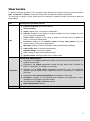
User levels
To prevent incorrect operation of the controller, three different user groups can log onto the controller:
User, Technician or Expert. Access by Technicians and Experts requires a password.
The controller is always in User mode when the controller is started or when new function data has
been loaded.
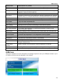
User
User
Displays and permitted actions
Function overview with control options
Value summary
Inputs: display only, no access to parameters
Outputs: changes to the status of outputs enabled for users, display of hours
run, no access to parameters
Fixed values: changes to the value or status of the fixed values enabled for
users, no access to parameters
Functions: display of the function status including start options from the
function status, no access to parameters
Messages: display of active messages, hiding and deleting messages
CAN and DL bus: no access to parameters
Default settings: no access possible
User: change of user (with password entry)
System values: setting the date, time, location data
All of the above plus:
Technician
Expert
Changes to the input parameters (except for type and measured variable), no
creation of new ones
Changes to the output parameters (except for type; status only if enabled for
User or Technician), no creation of new ones
Changes to the fixed values parameters (except for type and measured
variable; value and status only if enabled for User or Technician), no creation of
new ones
Changes to user defined designations and creation of new ones
Functions: changes to user defined input variables and parameters; output
variables are only visible in function status
All settings in the CAN and DL bus menus
Data administration actions
All actions and all displays are accessible.
5
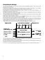
Functional design
The UVR16x2 controller has 16 sensor inputs to which temperature sensors, other sensors and
switches can be connected.
These sensors supply the controller with information about the status of the system. The controller
can also receive additional information via bus cables (CAN bus and DL bus).
The information is conveyed to the controller's function modules in the form of input variables, or is
utilised for the purposes of display only.
40 different functions are stored in the controller. Each of them can be applied multiple times, allowing
up to 128 functions to be programmed in total.
The input variables and the parameter settings entered by the user provide the function with all data
required to calculate the output variables.
Each function can be activated or deactivated with Enable. Decisions and set values are calculated
inside the function and made available as output variables.
The values of the output variables can have a switching effect on outputs or a control effect on
pumps, burners or heat pumps. There are 16 outputs available for this purpose. They can also be
made available to other functions or to other CAN bus devices via the CAN bus.
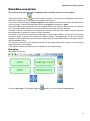
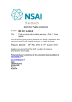
These features are illustrated in the following schematic diagram of a function module:
The 16 outputs perform various different tasks (switching output, output pair for mixers or dampers,
analogue outputs for speed control or modulation).
Up to 62 CAN bus devices can be linked together via the CAN bus. These CAN bus devices can
exchange information via CAN inputs and outputs.
The C.M.I. (Control and Monitoring Interface) allows remote access via a network and the internet.
6
Operation
Operation
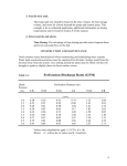
The UVR16x2 is operated via a 4.3" touchscreen. For greater ease of use, an operating pen is
provided, which can be found behind the flip-up cover.
View with open cover
Operating pen
LED indicator
You can use the pen to tap operating fields on the screen and can scroll the view displayed by sliding
it with the pen.
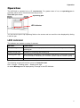
LED indicator
The indicator can indicate a variety of statuses.
Indicator
Explanation
Steady red light
The controller is booting up (= start routine after switching on, resetting or
updating) or
Steady orange light
Hardware is initialising after booting up
Flashing green light
After hardware initialisation, the controller waits about 30 seconds to receive
all the information necessary for a function (sensor values, network inputs)
Steady green light
Normal controller operation
The following sequence therefore occurs at Controller start:
Red – Orange – Flashing green – Steady green light
An active Message can be displayed by a change in the LED indicator.
7
Operation
Information on the display
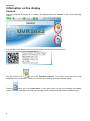
Version
After the controller is booted up (= started), the display shows the Version of the current operating
system.
You can then scroll down to view the serial number and the date of manufacture.
Tap the "Home icon"
to go to the Function overview. The function overview is the most
important menu for the user. There you can enter your settings and check sensor values.
Tapping
takes you to the main menu. In the main menu you can view settings and display
values in various sub-menus and can also change certain statuses that have been enabled for you.
8
Operation
Status line
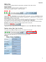
The top part of the display shows the output status, messages, faults, date and time.
Output status
Active outputs are highlighted against a green background.
In the following example, outputs 1, 3 and 6 are active.
Output 5 has been deactivated manually (Manual/OFF) and output 6 has been activated manually
(Manual/ON). Outputs that have been switched to Manual/OFF or Manual/ON are marked with a
hand symbol under the output number.
When a message is active, outputs may be switched to dominant off or dominant on. This is indicated
by a red border around the affected output (see chapter Main menu / Messages).
Output pairs (e.g. for mixer drive) are shown in the status line with a + between the output numbers.
Example: Outputs 8+9 and 10+11 have been programmed as output pairs
Tapping the outputs display takes you to the Outputs menu (see chapter Main menu / Outputs).
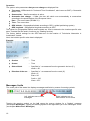
System values (date, time, location)
The system values Date and Time are shown in the status line at top right.
Tapping that status field takes you to the menu for the system values.
Example:
9
Operation
The system value parameters that you can change are displayed first.
Time zone - UTC stands for "Universal Time Coordinated", also known as GMT (= Greenwich
Mean Time).
Summertime – Yes if summertime is active.
Automatic time change – If Yes, the time will switch over automatically to summertime
according to the specifications of the European Union.
Date – The current date (DD.MM.YY).
Time - The current time
GPS latitude – Geographical latitude according to GPS (= global positioning system)
GPS longitude - Geographical longitude according to GPS
The values for geographical latitude and longitude are used to determine the location-specific solar
data. That data can be used in functions (e.g. shading function).
The factory default settings for the GPS data are for the location of Technische Alternative in
Amaliendorf, Austria.
Next, the location-specific solar data is displayed.
Example:
Sunrise
– Time
Sunset
– Time
Solar altitude
– Specified in ° as measured from the geometric horizon (0°),
zenith = 90°
Direction of the sun – Specified in ° as measured from the north (0°)
North = 0°
East = 90°
South = 180°
West = 270°
Messages, faults
The centre part of the status line displays messages and faults by means of warning symbols.
Left: indicates one or more
messages
Right: indicates one or
more sensor or bus errors
Tapping the warning symbol on the left opens the pop-up window for a "hidden" message
(see chapter Messages). Tapping the warning symbol on the right takes you to the "Messages" menu
(see chapter Main menu / Messages).
10
Function overview, general
Function overview
The function overview will only be displayed with controller version V1.04 or higher.
Tapping the "Home" icon
opens the function overview. This overview is designed to provide the
user with a simple way of controlling and monitoring the system.
The function overview can be freely designed by the programmer and can therefore look different on
every controller. It can be displayed with the aid of graphics or simply as a table.
Values selected by the programmer can be changed either by all users, by Experts only or by Experts
and Technicians. Many values (e.g. sensor values) can generally never be changed.
If multiple UVR16x2 controllers in the system are linked by CAN bus, the function overview can also
be programmed to display the values of other controllers.
The function overview can comprise several pages, in which case a Link (= link on the screen linking
to another page) is required for switching to a different page. The appearance of links can be freely
designed by the programmer. Access to some pages may be restricted to certain user groups (with or
without password entry).
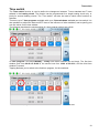
The function overview can be programmed with the first page showing an overview of the following
pages with links to those pages.
Touching the relevant link takes you to the display on the required page.
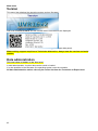
Examples:
Start page with 4 links
From the start page (= first page), tapping
takes you to the controller's main menu.
11
Function overview, general
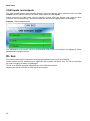
Page with simple graphical design and link at bottom left for switching to the next page:
Page with display in table form and two links, forward and back:
12
Function overview, general
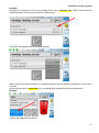
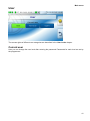
Page with graphic elements and links to time switch, calendar and settings:
Page with graphic elements and "back" link:
You can go back to the page displayed previously by tapping
To go to the start page of the function overview, tap
From the start page, tapping
.
.
takes you to the controller's main menu.
13
Function overview, general
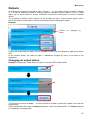
Changing values
Tapping the required value opens either a keypad or a selection box. Values can only be changed if
they have been enabled for the user level by the programmer.
Example:
Changing the set room temperature "T.room standard" via a keypad:
The keypad then appears:
The current value is shown (example: 20.0 °C).
The top line shows the permitted entry range (example: 0.0 – 45.0 °C).
You can make entries using either the correction keys (--, -, +, ++) or the numeric keys. The
correction keys - and + change the value of the first digit to the left of the decimal point (units); keys -and ++ change the value of the second digit (tens).
The arrow key
Finish your entry with
14
shortens the value by one digit place; key
; discard it with
.
sets the value to zero.
Function overview, general
Example:
Changing the operating mode of the heating circuit with a selection box ("RAS" means that the
operating mode is set by the room sensor's slide switch):
A selection box appears with all possible settings:
When you tap the required setting, it is changed and the required setting is displayed in the function
overview.
Some functions have a touch field e.g. for starting DHW demand outside the demand time.
Example:
Tapping the field starts the action.
15
Heating circuit function
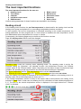
The most important functions
The most important functions for the user are:
Heating circuit
Blind control
Time switch
Maintenance
Calendar
Heat meter count
Individual room control
Start-stop
DHW demand
Solar control
Various setting parameters for these functions are described in the following:
Heating circuit
In the heating circuit function, the set flow temperature is determined for the heating circuit and the
heating circuit pump is switched off or on according to adjustable shutdown conditions.
In many systems, the set flow temperature is calculated according to the outside temperature, the
setting parameters, the time program and, if a room sensor is installed, the room temperature, and is
then defaulted as the set temperature for a mixer or a boiler.
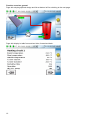
Consequently, the following pages may be visible on the function overview.
Page with display values which cannot be changed:
Operating mode shows the currently active operating mode. The operating mode is set by the
controller setting for "Operation", the calendar function, the maintenance function, the "Window
contact" status or the "External switch" status. Depending on the status of these functions and input
variables, the operating mode may therefore vary from the internal setting for "Operation".
The Room temperature and the Flow temperature are the current measurements.
The Effective set room temperature and the Set flow temperature are the current set values.
When the heating circuit pump is switched off due to a shutdown condition or the heating circuit is in
standby mode, the set flow temperature is shown as 5 °C.
If the outside temperature sensor is faulty or the sensor lead is disconnected, the heating circuit
switches to Fault mode. In that case, the heating circuit is controlled to a fixed outside temperature of
0 °C. The fault on the outside temperature sensor is displayed in the upper status line if "Sensor
check" is activated.
16
Heating circuit function
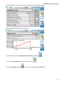
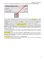
Settings for the heating circuit operation with an additional link to the heat curve parameters:
You can change the internal operating mode of the function by changing the Operation setting. RAS
indicates that the setting of the room sensor is applied. If there is no room sensor installed, the setting
Time/auto applies the time switch's time program to the heating circuit. Other options to choose from
are Standard (= continuous heating mode), Setback (= continuous setback mode) or Standby/frost
protection (= heating circuit shutdown subject to the programmed frost protection conditions).
In Standby mode, the controller's frost protection function is operational. The programmer defines
the frost protection limits for the outside temperature and (if a room sensor is installed) the room
temperature. If one of those temperatures falls below the limit, frost protection is activated and the
heating circuit pump is switched on. The set flow temperature will be set to at least the programmed
minimum temperature. The activation of frost protection can be delayed when changing over from
standard to setback mode.
The internal operating mode may differ from the actual operating mode because the calendar
function, the maintenance function, window contacts and the "External switch" can override the
internal operating mode.
T.room setback is the required room temperature in setback mode if a room sensor is installed. If
there is no room sensor, this value represents a notional room temperature. Changing this value
moves the heat curve upwards or downwards to a parallel position, thus increasing or decreasing the
calculated set flow temperature.
T.room standard is the corresponding value for heating mode.
The changeover between heating mode and setback mode is carried out with the Time switch
function, which is described in the next chapter.
17
Heating circuit function
Settings for the heat curve:
Room influence: If a room sensor is installed, you can use this setting to define how much influence
the actual room temperature should have on the calculation of the set flow temperature. Values higher
than 50 % will have a very great influence and will be unfavourable in most cases.
Level: This parameter influences the calculation in the same way as changing the values T.room
standard and T.room setback, but affects both heating mode and setback mode. It too moves the heat
curve to a parallel position. Negative values can be entered as well.
The heat curve can be defined using two different methods:
Definition of the set flow temperature by two outside temperature points at +10 °C and -20 °C, or
by the slope.
In the example above, the method with the two temperature points was chosen. With T.flow +10 °C
and T.flow -20 °C, both the slope and the curvature of the heat curve can be defined, allowing the
heat curve to be optimally matched to the system.
If the "slope" method is chosen, the slope can be defined instead of the two temperature points.
.
18
Time switch
Time switch
The Time switch function is used to define the changeover between T.room standard and T.room
setback in the heating circuit. The function can be programmed for a single heating circuit only, or
jointly for several heating circuits. The "Time switch" can also be used to switch other functions or
statuses.
There are up to 7 time programs available with up to 5 time windows available per time switch. It is
also possible to subject the start and OFF times to the influence of other variables, and to specify your
own set values for the time window.
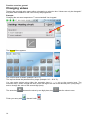
The following describes the simple setting of a time program without set values:
In Time program 1 the days Monday – Friday have been selected (the red keys). The first time
window goes from 06:00 to 09:00 h, the second one from 16:00 to 22:00 h, and the third time
window is unused.
Tapping 2 allows you to switch to the 2nd time program, for the weekend:
For the weekend, only the first time window from 07:00 to 23:00 h has been set.
19
Calendar
Calendar
The calendar function overwrites the internal settings and specifications of the time switch for the
heating circuit. The following calendar modes can be set:
Holiday
Party
Bank holiday
Standby
There are up to 10 date windows available in which each mode can be set. Up to 3 set values can be
set in each mode, one of which can be applied in the heating circuit as the set room temperature.
The respective appearance in the function overview can vary greatly. The following describes
one possibility:
Link to the set values
The calendar function is currently Inactive. Here you can define whether the calendar mode should
be applied once or annually. Tapping the displayed Operating mode allows you to set the required
operating mode:
After selecting the operating mode, the Start and End are selected.
A Holiday has been set from 26/02/2015 09:00 h to 28/02/2015 20:00 h. During that time, the
programmed set room temperature ("Set value") for holiday will be applied.
The Holiday (6) operating mode is visible in the Heating circuit menu when the conditions are met:
20
Calendar
Depending on programming, there may also be another window with adjustable Set values for each
mode:
For the Bank holiday operating mode, time windows can be set with different set values for the times
inside and outside the time window.
The set value for Inactive (0 °C) is displayed but is not actually applied in the heating circuit function.
21
Individual room control
Individual room control
This function is specially designed for the control of zone valves for heating and/or cooling of
individual rooms. Room temperature thresholds and the operating mode switch on the room sensor
can be utilised to switch between heating and cooling. Shutdown conditions prevent heating or
cooling beyond the outside temperature thresholds.
The floor temperature can also be monitored in order to prevent excessive cooling or heating of the
floor.
Example:
The highlighted Set room temperature can be an adjustable setting. However, this value can also be
a set value defaulted by a time program in a Time switch function.
All other values are display values indicating the status of the room.
If both heating and cooling are provided, the operating mode switch of a RASPT, RAS-PLUS or
RAS-F room sensor can be used to define the operating mode of the function:
AUTO: The system switches automatically between heating and cooling according to settings.
STANDARD: Only heating mode is allowed.
SETBACK: Only cooling mode is allowed (frost protection remains active).
22
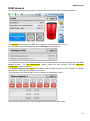
DHW demand
DHW demand
This function is used in many systems to define the domestic hot water cylinder temperature.
The Demand is currently set to OFF, so the effective set temperature is only 5 °C.
You can define the set temperatures via the Settings key (gearwheel):
The DHW demand can be switched between two set temperatures via a time program from the Time
switch function. The Set temperature applies inside the time window, and the Minimum
temperature applies outside it.
The Single charging start key can be used to start demand outside the time window. It remains
switched on until the set temperature is reached.
The time switch may look similar to the time switch for the heating circuits:
Here a uniform time of 07:00 – 20:00 h has been selected for the entire week.
23
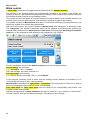
Blind control
Blind control
In Auto mode, the blind control applies the set position from the Shading function.
The settings of the shading function are programmed according to the design of the blinds, the
position of the sun, and restrictions imposed by the building. Every building face (cardinal direction)
and window situation requires its own shading function.
The shading function calculates the required setting of the blinds based on the cardinal direction, the
position of the sun at the particular time, and restrictions imposed by parts of the building.
It is possible to switch to Manual mode and open or close blinds manually by pressing the keys or via
digital input signals from external blind pushbuttons.
After the manual action, the function remains in Manual mode until changeover to automatic mode.
The changeover from manual to automatic mode can be triggered by simultaneously pressing the
external blind pushbuttons for Open blind and Close blind, by pressing the Switching to automatic
mode key, or at a changeover time defined by the programmer (e.g. 24:00 h).
The two percentage values for the Actual position specify the following positions:
1st percentage: slat inclination,
0 % = horizontal, 100 % = vertical
With roller shutters, this value is always 0 %.
2nd percentage: lowering level
0 % = blind or shutter at the Top, 100 % = at the Bottom
In the example, automatic mode is active and the shading function defaults an inclination of 0 %
(= horizontal) and a level of 98 % (almost closed).
Manual mode is activated with Open blind or Close blind. The blind opens or closes for as long as
the key is being tapped, and automatic mode is deactivated.
Fully open blind and Fully close blind move the blind into its corresponding end position, and
automatic mode is deactivated.
Subject to programming, a Safety shutdown may also be specified, e.g. by means of a wind sensor.
This will move the blind into a predefined position, overriding any other settings.
24
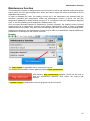
Maintenance function
Maintenance function
The maintenance function is designed as a service function for a flue gas inspector and/or as a simple
burner switch for a flue gas emissions test. When the function starts, the burner is switched on for an
adjustable total runtime.
In order to dissipate the heat, the heating circuits set in the parameters are activated with the
maximum permitted flow temperature. While the maintenance function is active, the set flow
temperature displayed for these heating circuits is 5 °C, the effective set room temperature displayed
is 25 °C and the operating mode displayed is "Maintenance (10)".
Once the heat generator demand is switched off (function stopped), the heating circuits involved
remain active for a further three minutes in the special "Maintenance" mode in order to dissipate
residual heat from the boiler. Only then does the heating circuit return to the previous operating mode.
Subject to programming, the maintenance function may be able to be started with external switches or
pushbuttons, or directly from the function overview.
Example:
The Total runtime is adjustable and is currently 20 minutes.
The maintenance operation can be started by tapping Start maintenance.
After starting, Stop maintenance appears, which can be used to
stop the maintenance operation even before the runtime has
expired.
A runtime counter is displayed so the time progress can be monitored.
25
Heat meter, Start-stop
Heat meter
The heat meter is a very useful function for solar thermal systems, if a flow sensor is installed.
The status of the system and its yields can be viewed at any time, allowing you to easily check that
the system is in good working order.
To capture the amount of heat, the controller requires the flow temperature, return temperature and
flow rate. Using that data and making allowance for an antifreeze component, the controller calculates
the output (in kW) and meters the energy (amount of heat in kWh).
A heat meter can of course be used for other system components as well (e.g. heating circuits). The
heat meter is not calibrated and therefore must not be used for billing purposes.
Example:
Start-stop
This function can be used to execute simple switching tasks. A pushbutton or an on-screen key is
used to switch a consumer or another function on or off.
Example: External lighting
26
Solar control
Solar control
The solar control starts or stops a solar pump based on the differential between the collector
temperature and a reference temperature (e.g. temperature at the bottom of a cylinder). Option: use
of a limit sensor (e.g. temperature at the top of the cylinder).
Start conditions for the solar pump:
1. The collector temperature must exceed the minimum collector temperature and must not
exceed the maximum threshold "T.coll. max.".
2. The set differential between the collector temperature and the reference temperature must be
exceeded.
3. The reference temperature must not yet have reached its maximum limit "T.ref. max.".
If the optional limit sensor is used, it must not have reached the limit temperature.
Example (without limit sensor) with a link to the settings:
When the collector exceeds a certain temperature (e.g. 130 °C) the system comes to a standstill and
it is assumed that steam is present in the collector, usually making circulation of the heat transfer
medium impossible. For this reason, the collector sensor has an adjustable maximum limit, T.coll.
max. If that limit is exceeded, the solar function stops and is not enabled again until the collector
temperature drops below a certain level (usually 110 °C). This protective function prevents
overheating of the solar pump due to lack of circulation.
The maximum cylinder temperature T.cylinder, max bottom should be selected according to
whether the cylinder is used as a DHW or as a buffer cylinder.
27
Messages
Messages
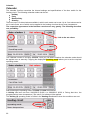
Sensor and bus errors
Subject to programming, the "Messages" menu may also display faulty sensors and incorrect CAN
and DL inputs. Faults of this kind are indicated by the right-hand warning symbol in the status line.
Tapping the warning symbol takes you to the Messages menu. The incorrect inputs are displayed
there.
Example:
Sensor display has red
border = error
The display of 9999.9 °C for sensor 1 indicates an interruption (sensor faulty or lead break).
If -9999.9 °C was displayed, it would mean a short circuit in the sensor or sensor lead.
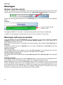
Messages with pop-up window
If the programmer has included Messages in the programming, they will be indicated by pop-up
windows in different colours and by the left-hand warning symbol in the upper status line. A
warning tone may also be issued.
There are four different types of messages, with varying display priority: Error, Fault, Warning and
Message.
Messages can switch outputs to dominant on or off, which is displayed by a red border around the
output in the status line.
Hiding a message
The message window will not close until you tap Hide message. If the message has not been
deleted, tapping the warning symbol causes the message window to reappear.
Switching off the warning tone
The warning tone can be switched off by tapping Warning tone off or Hide message in the message
window.
Deleting a message
The message and the warning tone can be deleted directly on the controller in the message window.
The message cannot be deleted until the cause for the message has been removed.
Fault message type only: A specific Reset fault output variable is available in order to reset external
devices. Activating "Reset fault" (in the message window or in the function status) generates an ON
pulse lasting three seconds regardless of whether the message cause still exists at that time or not. If
the event no longer occurs after the pulse, the message is deleted as well. This pulse can be used
elsewhere in programming as well and therefore has various effects.
28
Messages
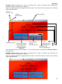
Example: Error message type, output 1 dominant OFF, output 2 dominant ON, warning tone
activated, output for warning tone: output 12.
After the message has been triggered and the cause of the fault has been removed, the following
display appears (red):
Output 1
dominant OFF
Output 2
dominant ON
Message window
Warning symbol
Hide message =
close the
message window
Time
Message name
Deleting a message
Message type
(only possible when
the cause for the
Visible only with
message has been
"Fault" message type
removed)
If the message window has been hidden, it can be shown again by tapping the warning symbol in
the status line.
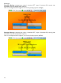
Example: Fault message type, output 1 dominant OFF, output 2 dominant ON, warning tone
activated, output for warning tone: output 12.
After the message has been triggered and the cause of the fault has been removed, the following
display appears (red):
29
Messages
Example: Warning message type, output 1 dominant OFF, output 2 dominant ON, warning tone
activated, output for warning tone: output 12.
After the message has been triggered, the following display appears (orange):
Example: Message, message type, output 1 dominant OFF, output 2 dominant ON, warning tone
activated, output for warning tone: output 12.
After the message has been triggered, the following display appears (yellow):
30
Messages
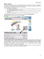
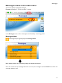
Messages menu in the main menu
This menu displays activated messages.
Example: Message 21 "DHW circulation" is active.
In the Messages menu, active messages are indicated by a warning symbol.
Message status
Selecting the plus sign displays the message status.
More display values can be shown by sliding the display with the pen.
Once the cause for the message has been removed, the message can be deleted from within the
message status as well.
31
Main menu
Main menu
The main menu contains all the elements and parameters that experts require to program the
controller. In other words, programming can also be performed directly on the controller. Generally,
however, programming is performed on a PC using the TAPPS2 programming software and then
loaded onto the controller.
Users have only restricted access to this data.
The individual menu items are described in the following.
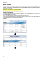
Value summary
This screen shows the current measurements for inputs 1 – 16, the DL inputs and the analogue and
digital CAN inputs, in tabular form.
The DL and CAN inputs are revealed by scrolling down from the inputs.
These inputs allow measurements or digital states (ON/OFF) of DL sensors or other CAN bus devices
to be transferred to the controller and processed there.
Example:
32
Main menu
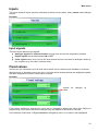
Inputs
This menu shows all inputs (sensors, switches) and their current values. Users cannot make changes
to them.
Example:
Input signals
There are three different input signals:
Analogue signals are numerical values coming from sources like temperature sensors
Digital signals are the state values ON or OFF
Pulse signals come from sources like flow sensors and are converted to analogue values by
the controller (e.g. flow rate in litres per hour).
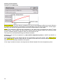
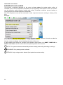
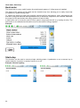
Fixed values
In this menu you can define up to 64 fixed values which can be used as input variables for functions.
When this item is selected in the main menu, the fixed values already defined are displayed together
with their designation and their current value or status.
Example:
Cannot
users
be
changed
by
Fixed values enabled for changing by users can be changed by tapping the value field. Subject to
programming, fixed values that can be changed may also appear in the function overview.
In the example, fixed value 2 (Digital) cannot be changed by users, so its value is not highlighted.
33
Main menu
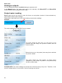
Changing a fixed value
Example: Changing fixed value 1 from 50 °C to 60 °C
Entering the required fixed value
A keypad is displayed for entering numerical values.
The current setting is shown (here: 50.0 °C).
The top line shows the range in which entries are possible (here: 50.0 – 65.0 °C). The permitted
setting range is predefined by the programmer.
You can make entries using either the correction keys (--, -, +, ++) or the numeric keys. The
correction keys - and + change the value of the first digit to the left of the decimal point; keys -- and
++ change the second digit (the tens).
shortens the value by one digit;
Finish and save your entry with
sets the value to zero.
; discard it with
.
After changing and saving the entry, the changed value is shown.
34
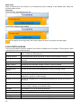
Main menu
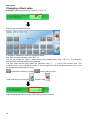
Outputs
All programmed outputs are displayed here. Outputs 1 – 11 are always switching outputs. Outputs
12 – 16 can be switching outputs or analogue outputs. Analogue outputs supply a 0-10 V or PWM
signal, e.g. for speed control of pumps, modulation of burners or heat pumps, or control of special
mixers.
The programmer defines which outputs can be changed by users. Those outputs appear with a
border around their output status, forming an operating field for changing the status.
Example:
Cannot
users
be
changed
by
Outputs the output status of which can be changed by users can be changed by tapping the status
field.
In the example shown, the status of output 1 cannot be changed by users, so its status is not
highlighted.
Changing an output status
Example: Changing the output status of output 2 from Auto/OFF to Manual/ON.
The outputs must be set to Auto/..... for the controller to be able to switch the outputs in line with the
programming.
If set to Manual/ON, the output is always switched on, and if set to Manual/OFF it is always switched
off, regardless of programming.
35
Main menu
Analogue outputs
You can change the status of enabled analogue outputs as well.
In the Manual status, the output value can be set manually; with Manual/OFF and Manual/ON,
values defaulted by the program will be output.
Output meter reading
Every output has its own meter to count the hours run and pulses (number of times switched on).
Users cannot delete meter readings.
Tapping the output takes you to the view showing current meter readings.
Example:
The meter reading since 09/07/2015 can be viewed.
The meter shows the total hours run, the hours run the
previous day and today, the previous runtime and the
current runtime.
Below the hours run, the pulses (how many times switched
on) can be viewed.
The meter shows the total number of pulses (times
switched on), the number of pulses on the previous day
and the number today.
PLEASE NOTE: The meter readings are saved to the internal memory every hour. Therefore, in the
event of a power failure, no more than 1 hour of metering can be lost.
36
Main menu
Functions
This menu displays all programmed functions (= function modules).
Changing the programming of their parameters is not possible for users.
Example:
Function status
Selecting the plus sign displays the function status.
The values displayed are identical to the output variables of the function. The number of
output variables varies greatly depending on the function.
Example: Heating circuit
The heating circuit has a very large number of output variables, with the most important ones shown
first.
More display values can be shown by sliding the screen.
37
Main menu
Many functions allow the function to be started and meter readings to be deleted from within the
function status screen.
Examples:
DHW demand, start heating once only
Heat meter, deleting meter reading
If you tap the minus sign when the function status is open, the screen will close again.
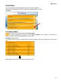
List of all functions
There are 40 different function modules from which a program can be created. This list gives a brief
overview of the role of each function.
Analogue function
Determines the highest or lowest value. Additional functions: average, total,
filter, multiplexer, demultiplexer
Heating demand
Heating demand issued by means of demand and shutdown sensors
Cooling demand
Demand for a cooling appliance issued by means of demand and shutdown
sensors
DHW demand
Heating demand issued by a DHW system
Range function
Determines the definable ranges in which a value is located.
Shading function
Defaults for the blind monitoring function
Individual room
control
Control of zone valves for heating and/or cooling individual rooms
Energy meter
Transfer of energy output from other sources and energy metering.
Gradient detection
Two different modes: slope detection = direction of a value change, gradient
detection = speed of a value change
Heating circuit control
Control of a heating circuit, switching the heating circuit pump and control of
the mixer.
Blind control
Applies the set position from the shading function or manual mode
Calendar
Defaults for operation of the heating circuit controller in the operating modes
Party, Holiday, Standby and/or Bank holiday
Cascade
Coordination of up to 8 (heating) demands
Curve functions
Option of assigning a Z value to X and Y values.
Monitoring function
Monitoring of sensors and differentials
Cooling circuit control
Mixer control of a cooling circuit; switching the cooling circuit pump.
Charging pump
Differential or thermostat control of a charging pump
38
Main menu
Pasteurisation
Pasteurisation for cylinders
Logic function
Uses logic parameters to determine results from digital inputs
Mathematics function
Various mathematical calculations
Message
Generating messages on the basis of definable events. When a message is
triggered, a pop-up window appears.
Mixer control
Maintains a constant temperature by means of a mixer
PID control
A system is controlled in such a way that a sensor is maintained at a required
constant value, or a constant differential is maintained between two sensors.
Profile function
Time-controlled output of numerical values, e.g. for screed drying
Sample & hold
Determines a value from the input variable at a particular time
Time switch
7-day timer with unrestricted use
Scaling function
Conversion of analogue values
Solar cooling
Cooling function to prevent overheating of solar thermal systems
Solar control
Differential control for solar thermal systems
Solar start/drainback
Two modes: start assistance for solar thermal systems; control of solar
thermal drainback systems
Solar priority
Priority ranking of solar monitoring functions when there are more than one
Start stop
A latching switch
Synchronisation
Generates date-dependent or time-dependent switching signals
Timer
Time interval function with unrestricted use
Comparison
Compares two (temperature) values (= thermostat)
Heat meter
Metering of thermal energy
Maintenance function
Service function for a flue gas inspector and/or a simple burner switch for a
flue gas emissions test
Conservatory
function
Opens a window for airing when a certain temperature is reached
Meter / counter
Counting of hours run or pulses (e.g. for metering of electricity, water or gas)
DHW circulation
Time control and temperature control of a DHW circulation pump
CAN bus
This menu contains all of the information and settings required to set up a CANopen network. Up to
62 CAN bus devices can be operated in one network.
39
Main menu
CAN inputs and outputs
The CAN network allows communication between CAN bus devices. When values are sent via CAN
outputs, other CAN bus devices can utilise those values as CAN inputs.
Values received via CAN inputs can be applied by other CAN bus devices and used for other
purposes in the programming. The CAN bus can also be used for logging data in a datalogger.
Example: CAN analogue inputs
The designation and current value of programmed CAN inputs and outputs are displayed. Users
cannot make changes to them.
DL bus
This menu contains all of information and settings needed to set up a DL bus network.
Sensor values from DL sensors can be applied in the controller via the DL bus. The DL bus can also
be used for logging of data in a datalogger.
The DL bus network operates independently of the CAN bus network.
Displays are similar to those for CAN inputs and outputs.
40
Main menu
User
The access rights of different user categories are described in the User levels chapter.
Current user
Here you can change the user level after entering the password. Passwords for each level are set by
the programmer.
41
Main menu
Version
This menu item displays the operating system version (firmware).
After that the serial number and the internal date of manufacture are displayed.
The serial number is also visible on the controller's rating plate (upper side panel).
When making support enquiries to Technische Alternative, always state the version and serial
number.
Data administration
This menu item is hidden in the User level.
In data administration, function data can be saved or loaded.
It is also possible to load firmware (the operating system) onto the controller.
All data administration actions can only be carried out from the Technician or Expert level.
42
Troubleshooting
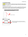
Troubleshooting
No display points to a power failure. Therefore first check the controller's power supply and then its
fuse (glass tube fuse 20x5 mm, 6.3 A fast) which protects the device from short circuits and
overcurrent due to earth faults. The glass tube fuse is located on the back of the controller behind a
screw cap.
Replacing the controller's fuse
The fuse has blown for a reason (short circuit or overload). You should therefore always have the
outputs checked by an electrician so that the controller is not damaged by further short circuits or
earth faults (e.g. scorched relay contacts). However, the fuse may also blow due to a short circuit in
the controller itself. In that case, the controller must be returned to the manufacturer for repair.
1. Pull the mains plug (so the controller is fully de-energised)
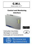
2. Detach the controller from its mounting base:
a) Open the top flap.
View with open cover
b) With two large screwdrivers, push both locking clamps
(arrows in the diagram on the left) and lever the device out
of its mounting base.
43
Troubleshooting
Glass tube fuse 20x5 mm,
6.3 A fast
On the back of the controller there is a small black screw cap (the fuse holder). Use a
screwdriver to turn the screw cap anti-clockwise a short way until the screw cap springs out.
3. Pull the fuse out of the fuse holder and check if the fuse has blown. If in doubt, replace the
fuse.
4. Re-insert the fuse holder and turn it clockwise a short way. Carefully place the controller back
in the mounting base. When inserting it, make sure that cables do not prevent the plug-in pins
from making contact with the plug-in strip.
5. Plug the mains plug back in the socket.
If problems occur with the heating circuits or the domestic hot water, first check that the time and
date are set correctly.
Then check the relevant time programs of the Time switch function. It may be that a heating circuit,
the DHW demand or the DHW circulation function is presently outside a programmed time window.
Many problems can be explained in that alone.
Check that an output has not been accidentally set to Manual (the hand symbol
will be shown
under the relevant output in the status line). The manual setting disables the control for that output –
the output (e.g. pump or mixer) is permanently set to "Manual/OFF" or "Manual/ON", regardless of
what the control actually requires.
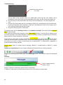
Sensor error: Check if a sensor input is showing +9999.9 °C (=lead break) or -9999.9 °C (=short
circuit).
Subject to programming the error may be indicated in the status line by a warning symbol:
Tapping the warning symbol takes you to the Messages menu. The incorrect inputs are displayed
there.
Example:
Sensor display has red
border = error
Sensor 1 shows an interruption (sensor fault or lead break).
If -9999.9 °C was shown, it would mean a short circuit in the sensor or sensor lead.
44
Troubleshooting
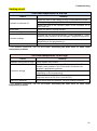
Heating circuit
The room temperature is too low
Cause
Remedy
Check the fuse for the heating circuitry in the distribution board
Heating emergency stop switch is switched on?
Controller is switched off
Check the fuse in the controller (back of the controller) 6.3 A
fast, 20x5 mm
Burner fault
Check the burner, remedy the fault
Radiator valve(s) set too low
Open radiator valve further
Increase the set room temperatures (T.room standard or T.room
setback); also possible in a time program if programming permits
Controller settings
Change the slope, curvature or level of the heat curve
(depending on the programming) *
Cannot be identified
If you cannot solve the problem, call your heating contractor
* For detailed instructions, see the sub-chapter Correcting the heat curve to solve room
temperature problems
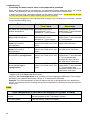
The room temperature is too high
Cause
Radiator valve(s) set too high
Remedy
Close radiator valve further
Reduce the set room temperature (T.room standard or T.room
setback); also possible in the "Time switch" function's time
program if programming permits
Controller settings
Change the slope, curvature or level of the heat curve
(depending on the programming) *
Check whether the heating circuit pump output and the mixer
output are set to AUTO (if not, set to AUTO)
Cannot be identified
If you cannot solve the problem, call your heating contractor
* For detailed instructions, see the sub-chapter Correcting the heat curve to solve room
temperature problems
45
Troubleshooting
Correcting the heat curve to solve room temperature problems
When the heating system is commissioned, the parameters should always be set by the heating
installer. We provide you with the following instructions for subsequent re-adjustment.
In order to save energy, corrections should only be made in small steps. You should wait at least
one day after each correction before making any further correction.
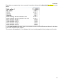
The corrections suggested in the following table all apply to the "Heating circuit controller" function
for the relevant heating circuit.
Solution for heat curve in
Temp. mode
Problem
Solution for heat curve in
Slope mode
All rooms are overheated at any Decrease the set room
outside temperature
temperatures T.room
standard or T.room setback
Decrease the set room
temperatures T.room standard
or T.room setback
Room temperature is too low at
any outside temperature
Increase the set room
temperatures T.room
standard or T.room setback
Increase the set room
temperatures T.room standard
or T.room setback
Room temperature too low in
winter but correct in
spring/autumn
Increase the "T.flow -20°C"
value in the "Heat curve" submenu
Increase the slope value in the
"Heat curve" sub-menu
Room temperature too high in
winter but correct in
spring/autumn
Decrease the "T.flow -20°C"
value in the "Heat curve" submenu
Decrease the slope value in
the "Heat curve" sub-menu
Room temperature right in winter
but too low in spring/autumn
Increase the "T.flow +10°C"
value in the "Heat curve" submenu
Increase the set room
temperatures T.room standard
or T.room setback and
decrease the slope value in
the "Heat curve" sub-menu*
Room temperature correct in
winter but too high in
spring/autumn
Decrease the "T.flow +10°C"
value in the "Heat curve" submenu
Decrease the set room
temperatures T.room standard
or T.room setback and
increase the slope value in the
"Heat curve" sub-menu
* Applies only to the Slope heat curve mode:
Adjust the set room temperature so as to balance out the temperature differential. Then change
the slope in the opposite direction by 0.05 per 2° of temperature differential.
Example: The room temperature is about 4 degrees too low in spring/autumn but is adequate in
winter. You therefore need to increase the set room temperature by that amount and decrease the
slope by 0.1.
DHW
DHW temperature is too low even though the cylinder is warm
The set DHW temperature is
too low
Set a higher temperature in the "DHW demand" function; check
the time program of the "Time switch" function
Air in the cylinder
Vent the cylinder (notify the installer)
46
Glossary
Glossary
As many users are non-experts and therefore unfamiliar with important terms used in heating and
control technology, here is a list – by no means exhaustive – of terms with explanations, in
alphabetical order:
Actual value
An actual value is a measured, momentary value of a control variable.
Analogue value
An analogue value is the momentary value of a measured variable (e.g.
temperature, radiation, humidity, etc.). The value can change continuously
to any value.
Buffer cylinder
In a heating system, the term buffer cylinder is used to refer to a thermal
store filled with water. It is used to compensate differentials between the
amount of heat generated and the amount of heat consumed, and for
smoothing of output fluctuations. This allows heat generation to proceed
largely independently of consumption, which for many energy sources
results in improved operating performance and efficiency.
Charging pump
For our controllers, the term digital value means a value of "OFF" or "ON"
(actually "0" or "1"). As an output variable, this constitutes the command to
switch an output off or on. As an input variable, a digital value can be used
to enable a function module, for example.
Digital value
For our controllers, the term digital value means a value of "OFF" or "ON"
(actually "0" or "1"). As an output variable, this constitutes the command to
switch an output off or on. As an input variable, a digital value can be used
to enable a function module, for example.
Display
The display is the screen on the controller which forms the interface
between the controller and the user.
Diverter valve
Diverter valves are also called three-way valves. By switching an actuator
on or off, the flow medium can be conveyed in two different directions, e.g.
either to a buffer cylinder or to a DHW cylinder.
Flow
In the field of heating technology, the term "flow" refers to the pipe in a
heating circuit which supplies the heating water, which is to say from the
generator to the consumer.
Function,
function module
40 different function modules (e.g. heating circuit controller) are stored in
the UVR16x2 controller, which can be linked to each other by means of
input and output variables. Input and output variables also form the
connection to the inputs and outputs. The modular structure of the
controller makes the UVR16x2 extremely versatile and universal in
application.
Heat curve
Radiators must be supplied with a certain temperature to heat the rooms of
a building adequately at different outside temperatures. The relationship
between the outside temperature and the flow temperature required for
heating is described by the heat curve. This curve varies from building to
building as it depends on a variety of factors.
The heat curve is set on the controller. It utilises an outside temperature
sensor, a room sensor and corresponding settings to change the level of
the flow temperature.
The heat curve is not completely straight because the variation in the heat
released from the radiators at different temperatures is not linear.
A correctly set heat curve will result in reduced heat losses and improved
control of room temperatures, thus saving energy.
Input
For our controllers, the term "input" means the sensors (e.g. temperature
sensor, radiation sensor, humidity sensor, etc.) which supply
47
Glossary
measurements to the controller (analogue input). An input can, however,
also be a simple on-off switch (digital input).
Input variable
The input variables of the function module provide the module with all the
data required for the internal decision. Frequently, these are temperatures.
K, kelvin
The kelvin (unit symbol: K) is the SI base unit of thermodynamic
temperature and is also a statutory temperature unit; it is used in this
manual to specify temperature differentials. The kelvin was named after
William Thomson, later Lord Kelvin, who at 24 years of age introduced the
thermodynamic temperature scale.
Mixer
The most common use of a mixer is as a heating circuit mixer. By moving
to intermediate positions, the mixer can direct a greater or lesser flow
from the heat source to the heating circuit, controlling the heating flow
temperature in accordance with the heat curve by mixing heating water of
different temperatures. The mixer is driven by a mixer motor; sometimes
also by means of bi-metal in the case of thermal mixers.
Output
For our controllers, the term output means either a switching output for an
item of equipment (e.g. pump) that is switched on or off by the controller, or
analogue outputs to generate controlled voltages (0-10 V or PWM).
An output is controlled by an output variable of a function. The UVR16x2
comes with 16 outputs as standard.
Output variable
An output variable represents the result of a function module. It can be
used to switch an output directly, or can serve as the input variable for
another module, and/or can be forwarded to other CAN bus devices as a
CAN output.
Return
The pipe carrying water back to a heat generator or cooling appliance is
referred to as the return.
Sensor
A sensor captures a physical entity (e.g. temperature) and transmits it in
the form of an electrical value (e.g. resistance) to a controller for
processing.
Set value
The set value or setpoint is the required value of a variable, to be reached
and maintained in a control loop. The value can be specified by the user or
by the controller itself.
48
Guarantee conditions
Note: The following guarantee conditions do not limit statutory rights to a warranty, but rather expand
your consumer rights.
1. Technische Alternative elektronische Steuerungsgesellschaft m. b. H. provides a two-year
guarantee from the date of purchase to the end user for all devices and parts it sells. Defects
must be reported immediately upon detection and within the guarantee period. Technical
support can supply the correct solution no matter what the issue. In this respect, contacting us
immediately will help to avoid unnecessary expense and effort in troubleshooting.
2. The guarantee includes free repair (but not the cost of on-site fault finding, removal, refitting
and shipping) due to processing and material defects which impair operation. Goods will be
replaced in the event that a repair is uneconomical in the opinion of Technische Alternative for
reasons of cost.
3. Excluded are losses resulting from the effects of a voltage surge or abnormal ambient
conditions. Likewise, no liability can be accepted if the device defect is due to: transport
damage for which we are not responsible, incorrect assembly and installation, incorrect use,
failure to observe the operating and installation instructions or incorrect maintenance.
4. The guarantee will become void if repairs or actions are carried out by people who are not
authorised to perform them or have not been so authorised by us, or if our devices are
operated with spare parts, auxiliary parts or accessories that are not considered to be original
parts.
5. Faulty parts must be returned to our factory with a copy of the proof of purchase and a precise
fault description. Processing is accelerated if an RMA number is requested via our homepage
www.ta.co.at. The defect must be clarified with our technical support beforehand.
6. Services provided under guarantee result neither in an extension of the guarantee period nor
in a commencement of a new guarantee period. The guarantee period for fitted parts ends
with the guarantee period of the whole device.
7. Further or other claims, especially those for compensation for losses other than to the device
itself, insofar as such liability is not required by statute, are excluded.
The controller's graphical interface is licensed by SEGGER.
Legal notice
This operating manual is protected by copyright.
Use outside the copyright requires the consent of Technische Alternative elektronische
Steuerungsgerätegesellschaft m. b. H. This applies in particular to reproduction, translation and
storage on electronic media.
elektronische Steuerungsgerätegesellschaft m. b. H.
A-3872 Amaliendorf Langestrasse 124, Austria
Tel +43 (0)2862 53635
Fax +43 (0)2862 53635 7
Email: [email protected]
--- www.ta.co.at ---
© 2015