1
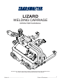
LIZARD
WELDING CARRIAGE
OPERATOR’S MANUAL
BEFORE USE, ENSURE EVERYONE USING THIS MACHINE READS AND UNDERSTANDS
ALL SAFETY AND OPERATING INSTRUCTIONS IN THIS MANUAL .
Serial #............................................
1
Date of Purchase............................
TRADEMASTER LIZARD WELDING CARRIAGE
IMPORTED & DISTRIBUTED BY
INDUSTRIAL TOOL & MACHINERY SALES
INDUSTRIAL TOOL
T
F
E
W
18 BUSINESS ST
YATALA QLD 4207 AUSTRALIA
07 3287 1114
07 3287 1115
[email protected]
www.industrialtool.com.au
WARRANTY TERMS
In addition to any warranties or conditions implied by applicable Statute or Regulations, Industrial Tool & Machinery
Sales warrants all of it’s products against defective workmanship and faulty materials for a period of twelve (12)
months from the date of purchase, unless otherwise stated. At our option we will repair or replace, free of charge,
any item on the condition that:
• The complete machine or tool is returned, freight prepaid to ITM or one of it’s authorised service agents as
directed by ITM, and is found to have a material or constructional defect.
• The machine or tool has not been subject to misuse, neglect or damage by accident.
• The fault is not a result of normal “wear and tear”.
• Written permission has been received from ITM prior to commencement of repair.
• Repairs, tampering or modification carried out by unauthorised personnel will void all warranty.
• Consumable items such as cutting tools, pilot pins, saw blades, grinding wheels etc. are NOT covered by
warranty.
Our goods come with guarantees which cannot be excluded under the Australian Consumer Law. You are entitled
to replacement or refund for a major failure and to compensation for other reasonably foreseeable loss or damage.
You are also entitled to have the goods repaired or replaced if the goods fail to be of acceptable quality and the
failure does not amount to a major failure.
TABLE OF CONTENTS
2
1. GENERAL INFORMATION............................................... 3
1.1. Application................................................................. 3
1.2. Technical data........................................................... 3
1.3. Technical data (with oscillator).................................. 5
1.4. Design....................................................................... 6
1.5. Equipment included................................................... 7
2. SAFETY PRECAUTIONS.................................................. 8
3. STARTUP AND OPERATION........................................... 10
3.1. Preparation................................................................ 10
3.2. Startup....................................................................... 12
3.3. Programming............................................................. 13
3.4. Welding procedure.................................................... 13
3.5. Operation...................................................................14
3.6. Using oscillator (optional equipment)........................ 15
3.6.1. Installation....................................................... 15
3.6.2. Welding with oscillation................................... 16
3.6.3. Operation.........................................................17
4. WIRING DIAGRAM............................................................ 18
5. GENERAL ASSEMBLY......................................................19
CONTROL PANEL ASSEMBLY........................................ 21
TORCH PLATE & CABLE ANCHOR ASSEMBLIES......... 22
DRIVE SYSTEM ASSEMBLY............................................ 23
DRIVE SYSTEM................................................................ 24
CONTROLLER HOUSING ASSEMBLY............................ 26
TORCH HOLDING ASSEMBLIES..................................... 27
GENERAL INFORMATION
1.
GENERAL INFORMATION
1.1.
Application
The LIZARD Welding Carriage is designed to produce continuous or intermittent welds using
MIG/MAG torches with handle diameter in 16–25 mm range (0.63–0.98’’). The machine can
work in PA, PB, PC, and PF welding positions. It is fixed by permanent magnets and contains
four wheel drive with speed adjustment. The machine also enables welding with oscillation when
equipped with an optional oscillator available on request.
1.2.
Technical data
3
GENERAL INFORMATION
Welding position
Power
Welding position
4
~ 115–230 V, 50–60 Hz
25 W
horizontal
PA (flat), PB (horizontal vertical), PC
(horizontal)
vertical
PF (vertical up)
Minimum path convex radius
1500 mm (60’’)
Minimum path concave radius
1500 mm (60’’)
Torch type
MIG/MAG
Torch diameter
16–25 mm (0.63–0.98’’)
Maximum torch reach
80 mm (3.15’’)
Maximum weight
horizontal work 12 kg (26.5 lbs)
of cables
vertical work
8 kg (17.7 lbs)
Welding material thickness
minimum 5 mm (0.20’’)
Ground clearance
5 mm (0.20’’)
Pulling force
horizontal work 220 N
vertical work
150 N
Torch adjustment range
35 mm (1.38’’, up-down, left-right)
Follower arm adjustment range
75 mm (2.95’’)
Horizontal speed
0–120 cm/min (0–47.2’’/min)
Vertical speed
0–110 cm/min (0–43.3’’/min)
Dimensions
382 mm (L) × 372 mm (W) × 390 mm (H)
15.0’ (L) × 14.7’’ (W) × 15.4’ (H)
Noise level
< 70 dB
Weight
8 kg (17.7 lbs)
GENERAL INFORMATION
1.3. Technical data (with oscillator)
Oscillation type
Oscillation amplitude for r=150 mm
(5.9’’)
Oscillation speed for oscillation
amplitude of 10 mm (0.4’’) and zero
delay on tips
Delay on tips
Maximum torque
Power
Weight
angular (maximum 11º)
1–30 mm (1–100%)
7–164 cycles/min (1–100%)
0–5 s
5 Nm (3.7 lb•ft)
37W
16 kg (35 lbs)
5
GENERAL INFORMATION
1.4. Design
The LIZARD welding carriage contains a drive system with controller, cross slides, two follower
arms, cable holder, and torch holder. The drive system comprises a gear motor that drives four
rubber wheels of high thermal resistance.
The magnetic unit with powerful permanent magnets fitted at the carriage bottom ensures
proper adhesion to ferromagnetic surfaces. Toggling the magnetic unit lever (Figure 1) to position
“0” reduces the intensity of the magnetic field, what helps moving the welding carriage during
positioning. The cross slides enable precise control of the torch holder position in both horizontal
and vertical axis. Additionally, the machine can ignite an arc through the arc ignition socket when
choosing a travel direction.
Follower Arm
Cross Slides
Oscillation
Socket
Torch Holder
Cable Holder
Control Panel
Drive System
Power Switch
Power Supply Socket
Magetic Unit Lever
Limit Switch
Arc Ignition Socket
Saftey Line Lug
Figure 1. LIZARD welding carriage design
6
GENERAL INFORMATION
LED Display
Knob F1
Knob F2
Speed Adjustment Knob
Figure 2. Control panel design
Arc ignition switch
(TEST / 0 / 1)
Travel Direction Switch
(left / 0 / right)
1.5. Equipment included
The LIZARD welding carriage is supplied with complete standard equipment in foam filled
cardboard box. The included equipment consists of:
•
•
•
•
•
•
•
•
•
Welding Carriage
– 1 unit
Foam Filled Cardboard Box – 1 unit
Power Cord
– 1 unit
Arc Ignition Cable
– 1 unit
Cable Holder
– 1 unit
Low Torch Holder
– 1 unit
Short Torch Holder
– 1 unit
4 mm Allen key
– 1 unit
Operator’s Manual
– 1 unit
7
SAFTEY PRECAUTIONS
2. SAFETY PRECAUTIONS
1.
2.
3.
4.
5.
6.
7.
8.
9.
10.
11.
12.
13.
14.
15.
16.
17.
18.
19.
20.
21.
22.
23.
24.
25.
26.
27.
8
Before start, read Operator’s Manual and complete proper occupational safety and
health training.
Machine must be used only in applications stated in Operator’s Manual.
Machine must be complete and all parts must be genuine.
Power supply specifications must conform to those stated on rating plate.
Power supply socket must be equipped with grounding pin.
Never carry machine by cord or yank it to disconnect plug from socket. It may cause
power cord to break and result in electric shock.
Bystanders must not be present in immediate vicinity of machine.
Before start, check condition of machine and electrical installation, including power
cord, plug, control panel, and wheels.
Keep machine dry. Exposing it to rain, snow, or frost is prohibited.
Ensure proper lighting at worksite.
Never use machine in vicinity of flammable fluids or gases, or in explosive environments.
Make sure that rubber of driving wheels is clean and not damaged.
Never disassemble driving wheels cover.
Remove objects attracted to chassis by magnetic unit.
Transport and position machine using carrying handle, with magnetic unit lever set to
position “0”.
Place machine on ferromagnetic material in such a way that wheels always touch
surface and there is no contact between surface and chassis.
Do not stay underneath machine placed at heights.
Plug power cord into mains only when power switch is set to position “0”.
Keep power socket clean. Do not use compressed air for cleaning purposes.
Mounting torches other than MIG/MAG type or torches with handle diameter outside
16–25 mm range (0.63–0.98’’) is prohibited.
Maximum torch reach must not exceed 80 mm (3.15’’).
Keep torch cables from touching surface (they must be suspended to reduce carriage
load). Use only cables which maximum weight is 12 kg (26.5 lbs) for horizontal work
and 8 kg (17.7 lbs) for vertical work.
Operating in welding positions: PD (horizontal overhead), PE (overhead), and PG
(vertical down), as well as on curvatures with convex (concave) radius lower than
1500 mm is prohibited.
When operating at heights, use safety line to protect machine from falling down.
Always use eye protection (welding helmet, shield, and screen), hearing protection,
gloves, and protective clothing during operation. Do not wear loose clothing.
Before every use, inspect machine to ensure it is not damaged. Check whether any
part is cracked or improperly fitted. Make sure to maintain proper conditions that may
affect machine operation.
Never try to manually stop motion of machine. For this purpose set travel direction
switch to position “0”.
SAFTEY PRECAUTIONS
28.
29.
30.
31.
32.
Perform all maintenance work only with power cord unplugged from power socket.
Perform all repairs only in service centre appointed by seller.
If machine falls on hard surface, from height, is wet, or has other damage that could
affect technical state of machine, stop operation and immediately send machine to
service centre for inspection.
Never leave machine unattended during operation.
Remove from worksite and store in safe and dry location when not in use.
WARNING! Safety rules must be closely observed.
9
STARTUP AND OPERATION
3. STARTUP AND OPERATION
WARNING! Read safety precautions before starting.
3.1. Preparation
Use carrying handle (Figure 3) for transportation and positioning at the worksite. Set all levers
to position “0”: power switch, magnetic unit lever, arc ignition switch, and travel direction switch.
Knobs securing Cable
into Holder
Cable Holder
Levers securing Cable
Holder position
Precise Torch position
adjusting knobs
Carrying Handle
Levers securing Torch
position and angle
Bolts securing
Follower Arms
Knob securing Torch
into Holder
Figure 2. Control units
10
STARTUP AND OPERATION
Plug the cord into power supply socket. Put a torch into the torch holder and secure with the knob.
Then, put the torch cable into the cable holder, secure it with the knobs, and fix the holder in a
proper position using the levers. If the machine is to be used to control the welding device, plug
the arc ignition cable into the arc ignition socket. The cable works as a welding gun switch and
comprises two wire pairs of a different colour. Connecting each pair enables to control an arc
ignition of one welder.
To continuously track the travel geometry, set the first follower arm 10 mm (0.4’’) closer
to the machine than the second one (Figure 4). For this purpose, unscrew the bolts that secure
follower arms using supplied 4 mm Allen key and secure them after setting follower arms.
Travel Direction
Figure 4. Proper follower arms position
Toggle the magnetic unit lever from left (“0”) to right position (“I”), what changes the machine
adhesion to work surface from minimum to maximum. Loosen the levers to adjust the position
and angle of the torch, and set the torch position precisely using two knobs located at the cross
slides. If the work is to be done along the vertical axis, perform welding upward (position PF
according to EN ISO 6947). When operating at heights, attach a safety line to the lug. The safety
line is not included in standard equipment.
11
STARTUP AND OPERATION
3.2. Startup
Plug the power cord into mains and turn on the power by toggling the power switch to position
“I”. The initial menu with the current firmware version number shows up on the display. Then the
machine automatically checks for an oscillator connected to the oscillation socket. If the oscillator
is found, the “Oscillator found” confirmation message shows up. Once the initialization of the
control system is finished, the main menu from the Figure 5 shows up on the display.
Current operator state
Unit of speed
Program number
Value of speed
Press and hold the knob F1 for about 3 seconds to enter into the configuration menu to set
welding parameters.
3.3. Programming
The LIZARD welding carriage is equipped with a programming device that enables to define up
to 40 welding programs. After you enter into the configuration menu, proceed as described in the
Figure 6 to move among the parameters from the Table 1.
Value of parameter. Rotate the
knob F2 to change the value
by the higher step indicated in
Table 1. Press and rotate the
knob F2 to change the value by
the lower step.
Name of parameter. Rotate
the knob F1 to change among
parameters listed in Table 1.
Unit of parameter. You may
change it from the setting.
Figure 6. Configuration menu
To change the language of the menu, move to “Language”setting by rotating the knob F1 clockwise
and then rotate the knob F2 to choose among the available languages. Once you set the rest of
parameters from the Table 1, move to “Save setup”, choose a program number by rotating the
knob F2, and press the knob to save current values under this number. The action is confirmed
by showing “Done” message for a short period. To load a previously saved program, proceed as
described, but from the “Load setup” setting. Then, to move back to the main menu (Figure 5),
press the knob F1 and hold it for 3 seconds. If you do not save the chosen parameters, they will
be active only until you change the current program number in the main menu.
12
STARTUP AND OPERATION
3.4. Welding procedure
The Figure 7 shows a graphic description of the welding procedure that starts with the speed
value that is shown in the main menu when choosing travel direction. The first stage involves
making a weld and after that the carriage fills a crater (stage 2) for the chosen time. Next, the
carriage performs a backweld (stage 3) and then moves to the starting point of a next weld (stage
4). The process repeats until the carriage reaches a value of the total length.
Figure 7
7. Visualization of welding procedure according to parameters from Table 1
Parameter
Value
“Carriage speed” 0–52 in/min
[step: 1 or 0.1]
“Weld legth”
1–100 in
[step: 1 or 0.1]
“Skip”
0–40 in
[step: 1 or 0.1]
“Crater fill”
0–3 s
[step: 0.1]
“Backweld”
0–2 in
[step: 0.1]
“Total length”
“Unit”
“Save setup”
0–400 in or infinity
[step: 10 or 1]
cm or in
1 - 40
“Load setup”
1 - 40
“Language”
ENGLISH POLISH
SPANISH FRENCH
PORTUGUESE
TURKISH
Description
Speed of the carriage.
Length of a single weld.
Space between welds. If set to zero, ‘crater fill’ and
‘backweld’ are reset and the carriage works in the
continuous welding mode.
Time of filling a crater. Inactive, if ‘skip’ set to zero,
what is indicated by the (!) sign.
Length of a backweld. Shorter or equal to ‘weld
length’. Inactive, if ‘skip’ set to zero, what is indicated
by the (!) sign.
‘weld length’ and ‘skip’. If set to infinity, the program
executes until the carriage is stopped manually.
Unit used in the menu.
Pressing knob F2 saves the current configuration
under the indicated program number.
Pressing knob F2 loads the configuration saved
under the indicated program number.
Language of the menu
Table 1. Settings available in basic version of LIZARD welding carriage
13
STARTUP AND OPERATION
3.5. Operation
If the machine is to control a torch, toggle the arc ignition switch to position “I”. To check whether
the arc ignition cable is connected correctly, toggle the switch to position “TEST”.
WARNING: If the arc ignition switch is set to position “I”, the torch starts
welding immediately after choosing a travel direction.
In the “Ready” state of the main menu (Figure 5) you may change the current program ”Setup #1”
by simultaneously pressing and rotating the knob F2. Use the speed adjusting knob to change
the current welding speed. A clockwise rotation increases the speed by the step of 0.1, while a
counterclockwise rotation decreases it by the same step.
Use the travel direction switch to choose a direction of motion. The carriage will start moving
according to the chosen program parameters. The message indicating the current operating
mode shows up on the display during the program execution. You may control the carriage speed
during operation using the speed adjusting knob, however, the new speed will not be saved if you
change the current program in the meantime.
The carriage stops after reaching the total length and “Job’s done” confirmation message shows
up on the display. Now, to move into the main menu, toggle the travel direction switch to position
“0”. Once the work is finished, turn off the power using the power switch and unplug the power
cord from mains.
14
STARTUP AND OPERATION
3.6. Using oscillator (optional equipment)
3.6.1 Installation
Mount the oscillator according to the following instructions.
• Disassemble torch holder (1).
• Disassemble torch plate (2) by unscrewing bolts (3).
• Unscrew cap (4).
•
•
•
•
•
Fix arm (5) to oscillator (6).
Fix oscillator (6) to link (7) using two M5x16 screws (8).
Fix link (7) to cross slides (10) using two M5x20 screws (9).
Fix oscillator plug (11) to oscillation socket (12).
Fix torch holder (1) to oscillator arm (5).
15
STARTUP AND OPERATION
3.4.2. Welding with Oscillation
Once the oscillator is connected to the LIZARD welding carriage, several new settings appear in
the menu (Table 2). Welding with the oscillation is performed in a standard manner, however, the
welds form a shape similar to the shape shown in the Figure 8 instead of a straight line from the
Figure 7.
Parameter
Value
“Osc. amplitude” 0–100%
[step: 10% or 1%]
Description
Relative amplitude of the oscillation.
“Osc. speed”
0–100%
[step: 10% or 1%]
Relative speed of the oscillation. The higher the
speed, the shorter the oscillation period.
“Osc. delay 1”
0–5 s
[step: 1 or 0.1]
Delay in the top position of the oscillation.
“Osc. delay 2”
0–5 s
[step: 1 or 0.1]
Delay in the bottom position of the oscillation.
“Dwell times
lock”
YES
NO
Choosing YES locks the capability of changing
delay times during welding.
Table 2. Additional settings available with connected oscillator
Figure 8. Graphic description of oscillation parameters from Table 2
16
STARTUP AND OPERATION
3.6.3. Operation
Operating the LIZARD welding carriage with connected oscillator is performed similarly to
operating without the oscillator. During welding with oscillator, the menu indicated in the Figure 9
shows up on the display.
Rotation of the knob F1 changes
the oscillation amplitude by 1%.
Rotation of the knob F2 changes
the oscillation amplitude by 1%.
Figure 9. Menu shown during welding with oscillator
If “Dwell times lock” parameter is set to YES, pressing the knob F1 or F2 during operation does
not trigger any action. Otherwise, the delay parameters show up on the display and you may
adjust them online (Figure 10).
Rotation of the knob F1
changes the delay 1 by 0.1 s.
Pressing the F1 toggles from
showing delay 1 to oscillation
amplitude.
Rotation of the knob F2
changes the delay 2 by 0.1 s.
Pressing the F2 toggles from
showing delay 2 to oscillation
speed.
Figure 10. Menu that enables changing the oscillator dwell times
17
WIRING DIAGRAM
18
8
GENERAL ASSEMBLY
WA-LIZARD
ITEM
PART NUMBER
1
GLK-0476-01-11-00-0
2
DZW-0476-01-12-00-0
3
RKJ-0476-01-13-00-0
4
PNL-0476-02-02-00-1
5
PLY-0476-03-00-00-0
6
WSP-0476-05-00-00-0
7
UCW-0476-07-00-00-0
8
WOZ-0476-11-00-00-0
9
TBL-0476-15-01-02-0
10 UCW-0476-20-00-00-0
11 ZSP-0466-03-00-00-0
12 KUL-0466-13-00-00-0
13 NIT-000010
14 RKJ-000038
15 PDK-000017
16 PDK-000021
17 SRB-000075
18 SRB-000083
19 SRB-000114
20 WKR-000057
21 WKR-000092
22 NKL-0466-15-01-02-0
23.1 PWD-0466-18-00-00-0
23.1 PWD-0466-16-00-00-0
23.2 KBL-0466-17-00-00-0
23.3 UCW-0476-06-00-00-0
23.4* KLC-000007
23.5* INS-0239-64-00-01-0
* - not shown on drawing
VERSION
2347
2348
2646
2353
2355
2358
2359
2361
2062
2143
2072
240V
DESCRIPTION
Q-TY
HANDLE KNOB
1
LEVER
1
HANDLE
1
CONTROL PANEL ASSEMBLY
1
TORCH PLATE COMPLATE
1
SLIDE BRACKET
1
CABLE ANCHOR ASSEMBLY
1
DRIVE SYSTEM ASSY
1
NAME PLATE "Lizard"
1
TORCH HOLDING ASSY
1
CROSS SLIDES ASSY
1
BALL LEVEL
1
ROUND HEAD RIVET 2x6
4
HANDLEVER GN 300-45-M6-20-SW,
1
ROUND WASHER 5,3
4
ROUND WASHER 6,4
4
HEX SOCKET BOLT M5 x 10
8
HEX SOCKET BOLT M5x16
4
HEX. SOCKET BOLT M6x20
4
SSS M 6 x 6-8.8 FLAT POINT
1
SOCKET BUTTON HEAD CAP SCREW
4
M4x10
LOGO LABEL
1
POWER CORD 230V
1
POWER CORD 115V
1
CONTROL CABEL START-STOP
1
LOW TORCH HOLDING ASSY
1
HEX. WRENCH S=4
1
OPERATORS MANUAL
1
19
GENERAL ASSEMBLY
20
CONTROL PANEL ASSEMBLY
PNL-0476-02-02-00-1
ITEM
PART NUMBER
VERSION
4.1 USZ-0476-02-02-01-0
4.2 MSK-0476-02-02-10-0
2384
4.2.2 NKL-0476-15-01-01-0
4.3 MDL-0476-02-02-20-1
4.3.1
4.3.2
4.4
4.5
4.6
4.7
4.9
4.10
MDL-0476-02-02-22-0
SRB-000307
MDL-0476-02-02-30-1
PKT-000016
WZK-0476-02-02-02-0
OSL-000036
PDK-000058
WKR-000181
CONTROL PANEL ASSEMBLY
DESCRIPTION
PANEL PLATE SEAL
PANEL PLATE ASSY
PANEL PLATE LABEL
ELECTRONIC CONTROLLER
COMPLATE
DISPLAY MODULE,
PLASTIC SCREW M3x5
ENCODER MODULE,
POT. HANDWEEL K11/6D
DIRECTION OF MOTION WIRE SET
LEVER KEY COVER
WASHER,LOCK,INTERNAL STAR M3
CROSS RECESSED SCREW M3x6
Q-TY
1
1
1
1
1
3
1
3
1
2
7
7
21
TORCH PLATE & CABLE ANCHOR ASSEMBLIES
PLY-0476-03-00-00-0
ITEM
PART NUMBER
VERSION
5.1 LCZ-0476-03-01-00-0
2389
5.2 KST-0466-05-02-00-0
2106
5.3 SRB-000174
5.4 RKJ-000036
TORCH PLATE ASSEMBLY
DESCRIPTION
PLATE
BLOCK PLATE
HEX. SOCKET BOLT M5 x 16
HANDLEVER GN 300-45-M6-32-SW,
Q-TY
1
1
3
1
UCW-0476-07-00-00-0
ITEM
PART NUMBER
VERSION
7.1 KST-0476-07-01-00-0
2391
7.5 TRM-0219-06-16-00-0
2401
7.7 NKR-000121
7.8 RKJ-000036
CABLE ANCHOR ASSEMBLY
DESCRIPTION
CABLE HOLDING HOUSING
CLAMP PLATE I
KNURLED NUT M6
HANDLEVER GN 300-45-M6-32-SW,
Q-TY
1
1
2
1
8
1
5
7
22
DRIVE SYSTEM ASSEMBLY
WOZ-0476-11-00-00-0
ITEM
PART NUMBER
VERSION
8.1 ZSP-0476-01-00-00-0
2395
8.2 PKR-0476-02-00-00-0
2396
8.3 PRW-0476-04-00-00-0
2397
8.4 SRB-0476-08-00-00-0
8.5 USZ-0476-09-00-00-0
8.6 SRB-000278
8.7 WKR-000066
DRIVE SYSTEM ASSEMBLY
DESCRIPTION
DRIVE SYSTEM
CONTROLLER HOUSING COMPLATE
FOLLOWER ASSEMBLY,
FOLLOWER SCREW,
SEAL
EYE BOLT M6DIN 580
SOCKET SET SCREW M6x10
Q-TY
1
1
2
4
1
2
4
23
DRIVE SYSTEM
ITEM
8.1.1
8.1.2
8.1.3
8.1.4
8.1.5
8.1.6
8.1.7
8.1.8
8.1.9
8.1.10
8.1.11
8.1.12
8.1.13
8.1.14
8.1.15
8.1.16
8.1.17
8.1.18
8.1.19
8.1.20
8.1.21
8.1.22
8.1.23
8.1.24
8.1.25
8.1.26
8.1.27
8.1.28
8.1.29
8.1.30
8.1.31
8.1.32
8.1.33
8.1.34
8.1.35
8.1.36
ZSP-0476-01-00-00-0
PART NUMBER
VERSION
KRP-0476-01-01-00-1
2402
WLK-0476-01-02-00-0
WLK-0476-01-03-00-0
BLO-0476-01-04-00-0
2433
NPN-0476-01-05-00-0
RDK-0476-01-06-00-0
KOL-0476-01-07-00-0
2252
OSL-0476-01-08-00-0
OSL-0476-01-09-00-0
OSK-0476-01-10-00-0
LNC-0476-01-14-00-0
ZSL-0476-01-15-00-0
KRZ-0233-01-16-00-0
PDK-0233-01-21-00-0
PDK-0233-01-23-00-0
TLJ-0233-01-27-00-0
TLJ-0233-01-28-00-0
ZSP-0476-01-16-00-0
KOL-0466-01-08-00-0
LOZ-000038
NKR-000115
OBJ-000002
WPS-000027
KLK-000013
NKR-000013
PRS-000005
PRS-000018
PDK-000017
PDK-000021
PDK-000036
PDK-000037
PDK-000166
SRB-000061
WKR-000152
SRB-000083
WKR-000313
8.1.37
WKR-000092
8.1.38
WKR-000096
8.1.39
WKR-000290
8.1.40
8.1.41
8.1.42*
WKR-000134
WKR-000136
WZK-0476-01-17-00-0
8.1.43* PWD-0476-01-18-00-0
* - not shown on drawing
24
DRIVE SYSTEM
DESCRIPTION
Q-TY
FRAME,
1
FRONT DRIVE SHAFT ASSY,
1
BACK DRIVE SHAFT ASSY,
1
MAGNET BLOCK ASSEMBLY
1
CHAIN TENSIONER
1
GEAR CASE ASSEMBLY,
1
DRIVE WHEEL,
4
WHEEL GUARD RIGHT,
1
WHEEL GUARD LEFT,
1
SHAFT
1
ROLLER CHAIN
1
POWER SUPPLY ASSEMBLY,
1
CAM
2
DISTANCE WASHER 12,1x19x3,
4
WASHER 6,4x12x1,6,
1
SLEEVE BEARING 9x16x10
1
SLEEVE BEARING 12x16x10
1
LIMIT SWITCH ASSY
1
BEVEL GEAR z30
1
BEARING BALL 6001 SEALED
4
NUT NDM-16, M16x1,5,
2
HOLDER FOR FIX LEADS 4
4
WOODRUFF KEY 3x5x13
1
SPRING PIN 4x16
2
HEX NUT M4
2
EXTERNAL RETAINING RING 15z
2
INTERNAL RETAINING RING 28W
2
ROUND WASHER 5,3
4
ROUND WASHER 6,4
1
ROUND WASHER 5,5
4
ROUND WASHER 6,5
1
WASHER,LOCK,INTERNAL STAR 4,3
2
HEX SOCKET BOLT-M4X10
2
SCREW M4 x 16
1
HEX SOCKET BOLT M5x16
4
SOCKET BUTTON HEAD CAP SCREW 4
M3x8,
SOCKET BUTTON HEAD CAP SCREW 10
M4x10
SOCKET BUTTON HEAD CAP SCREW 4
M5x10
SOCKET BUTTON HEAD CAP SCREW 1
M6x12
SCR, M5 x 12 FHSCS
1
SCR, M5 x 16 FHSCS
12
ELECTRONIC CONTROLLER POWER 1
WIRE SET
EARTH CONDUCTOR
1
DRIVE SYSTEM
25
CONTROLLER HOUSING ASSEMBLY
ITEM
1.8.2.1
1.8.2.2
1.8.2.3
1.8.2.4
1.8.2.5
1.8.2.6
1.8.2.7
1.8.2.8
1.8.2.9
1.8.2.10
1.8.2.11
1.8.2.12
1.8.2.13
1.8.2.14*
PKR-0476-02-00-00-0
PART NUMBER
VERSION
PKR-0476-02-01-00-1
2400
SZP-0476-02-03-00-0
WZK-0476-02-04-00-0
WZK-0476-02-06-00-0
WZK-0476-02-05-00-0
NKR-000120
PDK-000165
PNK-000026
ZLP-000025
PDK-000060
NKR-000013
WKR-000435
WKR-000427
WZK-0476-02-07-00-0
* - not shown on drawing
26
CONTROLLER HOUSING ASSEMBLY
DESCRIPTION
Q-TY
CONTROLLER HOUSING
1
PIN
4
IGNITION WIRE SET
1
OSCILLATION MODULE WIRE SET
1
POWER WIRE SET
1
SAFETY NUT
1
LOCKING WASHER 12/19
1
LEVER KEY, 641 H/3
1
PLUG M12 SERIES713,
1
SPRING WASHER 4,3
2
HEX NUT M4
2
SCR, M4x16 FHSCS
1
CROSS RECESSED SCREW M3x10
6
IMPULSE WIRE SET
1
TORCH HOLDING ASSEMBLIES
UCW-0476-20-00-00-0
PART NUMBER
VERSION
ZRZ-0466-04-01-00-0
2093
WLK-0476-20-01-00-0
2710
TLJ-0419-04-02-03-0
RKJ-000036
TORCH HOLDING ASSEMBLY
DESCRIPTION
Q-TY
TORCH CLAMP ASSY,
1
SHORT TORCH BRACKET ASSY
INSULATION SLEEVE,
1
HANDLEVER GN 300-45-M6-321
SW,
UCW-0476-06-00-00-0
ITEM
PART NUMBER
VERSION
23.3.1 ZCS-0476-06-01-00-0
2093
23.3.2 TRM-0476-06-10-00-0
2710
23.3.2.1 TLJ-0419-04-02-03-0
23.3.2.2 RKJ-000036
LOW TORCH HOLDING ASSY,
DESCRIPTION
Q-TY
CLAMPING BLOCKS
1
TORCH BRACKET ASSY
INSULATION SLEEVE,
1
HANDLEVER GN 300-45-M6-321
SW,
ITEM
10.1
10.2
10.2.1
10.2.2
27