1
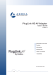
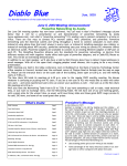
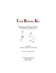
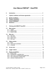
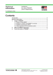
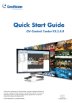
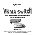
Fotonic E-series User Manual
Document number 402660 – Rev F
24/06/2015
WARNING!
Do not under any circumstances use the camera without first
reading the entire Quick Start Guide and User Manual.
1.
Introduction ..................................................................................................................................... 1
1.1
2.
3.
Overview.................................................................................................................................. 1
Quick start ....................................................................................................................................... 1
2.1
Package contents..................................................................................................................... 1
2.2
Installation and Setup.............................................................................................................. 1
2.2.1
Downloading and installing software .............................................................................. 1
2.2.2
Connecting Fotonic E-series cameras .............................................................................. 1
2.2.3
Mounting the Fotonic E-series cameras .......................................................................... 3
General about Time of Flight ........................................................................................................... 4
3.1
High dynamic range mode....................................................................................................... 4
4.
System of coordinates ..................................................................................................................... 5
5.
3D Display ........................................................................................................................................ 6
5.1
5.1.1
Settings Control ....................................................................................................................... 6
Sensor Settings .................................................................................................................... 6
Shutter ............................................................................................................................................. 7
Edge filter ........................................................................................................................................ 7
Median filter .................................................................................................................................... 7
5.1.2
Visualization Settings........................................................................................................... 7
Color mode ...................................................................................................................................... 7
Brightness limiter ............................................................................................................................ 7
Distance limiter ............................................................................................................................... 7
Define Plane .................................................................................................................................... 8
5.2
Save/Load Control ................................................................................................................... 8
6.
Ethernet camera .............................................................................................................................. 9
7.
Network configuration .................................................................................................................... 9
8.
Software development for Fotonic cameras ................................................................................. 10
9.
Hardware Description ................................................................................................................... 10
Technical Data ................................................................................................................................... 10
Physical Dimensions .......................................................................................................................... 10
1. Introduction
This is the Fotonic E-series User’s Manual. Please read this document carefully, as it will be your
guide when installing and using your Fotonic camera.
1.1
Overview
Fotonic E-series is a series of 3D cameras that use the Time of Flight technology. Variations within the
E-series include different Illumination power and lens angle of view. In the Fotonic E-series datasheet
you find detailed information about the different products.
The camera measures the surrounding in front of it in a single snapshot and sends the measurements
to a computer for display or further processing. With the E-series camera, you can run continuous
measurements of up to 58 images per second. All E-series cameras are smart cameras, meaning that
it’s possible to use the cameras internal ARM CPU for embedded image processing. You can read
more about this in chapter 8.
2. Quick start
2.1
Package contents
See Quick Start Guide for a complete list of package contents and accessories.
2.2
Installation and Setup
2.2.1 Downloading and installing software
Software for supported OS can be downloaded from the Fotonic homepage (www.fotonic.com).
There you can also download the SDK for embedded software development.
An example application called 3DDisplay is included in the installation. 3DDisplay is a 3D-viewer
which can be used to visualize the camera data as a 3D point cloud. It can also be used for recording
and playback of image sequences, and some basic data analysis. You can read more about 3DDisplay
in section 5.
2.2.2 Connecting Fotonic E-series cameras
The Fotonic E-series cameras need to be connected to a power supply and an Ethernet network.
Power supply, power cable and Ethernet cable are optional accessories to the Fotonic E-series
cameras.
The camera uses the following interfaces and pinout:
E40/70 4W/16W
Power interface
4-position M12 SPEEDCON, A-code
Pin1 +24V, Pin4 GND Pin 2,3 NC
IEC 61076-2-101
Signal interface
8-position M12 SPEEDCON, A-code
10/100/1000 Mbps Ethernet
IEC 61076-2-101
1
E70/40 48W
Power interface
4-position M12 Pluglink, T-code power
Pin1 +24V, Pin4 GND Pin 2,3 NC
IEC 61076-2-101
Signal interface
8-position M12 SPEEDCON, A-code
10/100/1000 Mbps Ethernet
IEC 61076-2-101
Please refer to our Quick start guide for information on how to setup the camera.
2
M12 Signal interface pin out for connection to RJ45 (T568B)
2.2.3 Mounting the Fotonic E-series cameras
The Fotonic E-series cameras are designed for passive cooling and shall at all times of operation be
connected to a heat sink.
Please refer to the datasheet for details on mounting thread positions.
3
3. General about Time of Flight
In Time of Flight systems the distance to objects in front of the sensor is measured by analyzing the
time for a light pulse to travel from an illumination source to the object and back to the sensor. The
illumination source in Fotonic cameras has a wavelength that is invisible to the human eye.
By modulating the light source and comparing the phase with the received signal, the distance can be
determined at each pixel of the sensor.
On
Light Source
Off
Bright
Returning Light
Dark
Active
Receptor A
The difference
between A and B
correlate to the
distance
Off
Active
Receptor B
Off
The maximum measurement distance is given by the modulation frequency.
3.1
High dynamic range mode
The E-series camera has a high dynamic range mode that uses two different shutter settings to
achieve a higher dynamic range. The decision which shutter to use for each pixel is made internally in
the camera.
4
4. System of coordinates
In order to introduce X, Y and Z coordinates, we need to define a coordinate system relative to the
camera. As shown in the picture below, the center of the camera coordinate system is defined as the
center of the camera lens. The x and y coordinates are defined as shown in the picture below with
the eye of the observer behind the sensor. Note that x and y coordinates, when mapped to the
display monitor, are defined as shown in the lower picture below. Pixel <0,0> in the display will map
to the upper left corner of the display.
The next picture shows the same information as above in a two dimensional view. Only one column
of the sensor is shown. A target (or object) T is mapped to a row, r, in the figure. The value of each
pixel is the distance Z to the target.
5
The depth distance (Z) produced by the API is the perpendicular distance from a target point to the
front glass of the camera. The depth distance is different from the range distance which is the
straight line distance from a target point to the camera. Note that if the target lies on the optical axis
of the camera lens, the depth and range distances are the same. See picture above. The camera
performs the necessary conversion from the range data to depth data for off-center targets.
5. 3D Display
3DDisplay is an example application which can be used to test and evaluate the Fotonic cameras.
Under the “settings” menu, there are two different control windows which can be activated or
deactivated. The functions of each control window are described in the subsections below. There are
also options to show more sensor information and statistics.
5.1
Settings Control
5.1.1 Sensor Settings
The top section of the settings window contains controls used to select camera and change camera
settings.
The drop-down list is used to switch between detected cameras. When 3DDisplay is started the first
camera in the list is selected. It is also possible to manually enter the IP number of Ethernet cameras
that cannot be found because they reside on a different network.
The “Pause/Play” button is used to start and stop playback from the camera. The “Step” button takes
one image and then pauses. The “Disconnect” button disconnects from the currently active camera.
6
Shutter
Shutter time is the same as exposure time in an analogous camera.
The Shutter time is the duration while the shutter will be opened and
the camera chip is exposed to light. The Shutter time is set in
milliseconds (ms). By selecting “Activate Multishutter”, a second
shutter timer becomes available.
Edge filter
The edge filter is an edge preserving filter used to remove flying
pixels. Flying pixels are pixels which lie on the border between two
objects and therefore have signal contribution from both. If the
objects are not on the same distance from the camera, such pixels
will take on a value in between.
Median filter
The median filter is a spatial filter within the camera which
smoothens the depth values.
5.1.2 Visualization Settings
3DDisplay has two main views, 2D and 3D which can be chosen by
selecting the corresponding mode in the visualization settings.
The 3D-view shows a 3D representation of the data received from the
camera. You can use the mouse to rotate the view and the scroll
wheel to zoom in and out. The 2D-view shows a 2D picture.
Color mode
There are different options regarding how the pixels are colored. This
is done using the options within the “Pixel Representation” box.
Using the “Color” or “Gray” option, the pixels are colored depending on their Z-value. The control to
the right of these boxes defines the distance represented by each color. The “IR reflectivity” mode
colors each pixel based on its brightness value. For the P70 camera there is also an option to color
the pixels from its RGB sensor.
The “Vertex Size” slider defines the size of each pixel when displayed in the 3D view.
Brightness limiter
The brightness limiter hides pixels below a certain brightness value in the visualization. Pixels with
low brightness are often more unreliable.
Distance limiter
The distance limiter defines the minimum and maximum distance at which pixels are drawn. The
color encoding for Z values is changed according to the limited Z range.
7
Define Plane
“Define Plane” is a simple tool to illustrate the measured distance from a plane in the scene instead
of from the camera. First press the “Define Plane” button when in 2D mode. Click on three clockwise
pixels in a plane surface in the 2D view. In the 3D view the distance used for pixel coloring will now
be calculated from the defined plane instead of from the camera. To restore this setting to the
default press the “Reset Plane” button.
5.2
Save/Load Control
The “Save/Load” settings window is used to save data from
the camera. You can save either one image or a sequence of
n images. The “Replay saved images” checkbox will replay all
saved images within a folder in a loop. Default, the files are
located in “My Documents\Fotonic\savedimages\” and
named after camera serial number and current date and
time. For each sequence, one human readable text file is
saved containing the camera settings used when recording.
When saving images on a slow computer some frames may
be lost since 3DDisplay makes no attempt to buffer images.
There are two different file formats supported:
PGM: Each frame is saved as four different files containing the X, Y, Z and Active Brightness
information. Each consecutive new frame in a sequence is saved in the same files.
PNG: Each frame is saved as four new files for X, Y, Z and Active Brightness. The PNG format is
compressed lossless and requires less storage.
Please read the documentation on FZ_GetFrame in the FZ-API Reference Manual for more
information about how the camera data is formatted.
8
6. Ethernet settings
Fotonic cameras support both dynamic IP configuration via DHCP and static IP assignment. A new
camera is default set to DHCP configuration.
A camera can always be started in a fallback mode by connecting only the power cable to the camera
and wait 30 seconds before connecting the Ethernet cable. The camera will then start with the
following IP settings:
IP: 192.168.1.10
NETMASK: 255.255.255.0
Note that in order to connect the camera directly to a computer, the network settings of both the
camera and the PC must be configured manually.
7. Network configuration utility
The FZ Ethernet Config utility is installed with the Fotonic FZ
installer and is located in the bin folder of the installation path.
The FZ Ethernet Config utility is used to change a camera network
configuration. When the tool is started a camera must first be
chosen by clicking in the drop-down list at the top or by entering
the IP address of the camera. When a camera is connected, its
current IP configuration is shown and can also be changed. The
9
“Use DHCP” checkbox is used to enable or disable the DHCP functionality.
It is also possible to connect to the camera by manually by entering its IP in the drop down box in
case it can’t be detected automatically.
8. Software development for Fotonic cameras
The software installer will install the API for the camera including its source code, an example 3D
viewer application, example source code, Matlab import scripts and documentation.
For information on how to develop your own software to interface the Fotonic cameras read the FZAPI Reference Manual.
9. Hardware Description
Technical Data
See product leaflet at www.fotonic.com for technical data for each Fotonic camera model.
Physical Dimensions
See product leaflet at www.fotonic.com for physical dimensions for each Fotonic camera model.
10