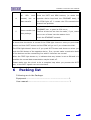
1
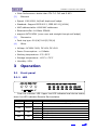
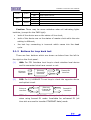
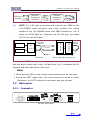
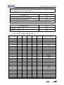
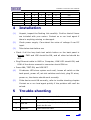
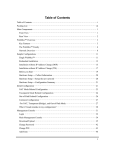
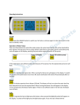
Eth-FE1 Ethernet to Framed E1 Interface Converter User Manual Version 1.0 March 21, 2007 TABLE OF CONTENT 1 OVERVIEW .........................................................................1 1.1 INTRODUCTION ..................................................................... 1 1.2 PRODUCT LINE...................................................................... 1 2 TECHNICAL SPECIFICATION ..............................................2 2.1 FEATURES ........................................................................... 2 2.2 TECHNICAL PARAMETER............................................................ 2 3 OPERATION........................................................................3 3.1 FRONT PANEL ....................................................................... 3 3.1.1 LED ............................................................................ 3 3.1.2 Buttons for loop back test .............................................. 4 3.2 BACK PANEL ........................................................................ 5 3.2.1 Connector.................................................................... 5 3.2.2 DIP on the panel .......................................................... 6 4 INSTALLATION...................................................................8 5 TROUBLE SHOOTING ..........................................................8 6 PACKING LIST ....................................................................9 Interface converter User Manual 1 Overview 1.1 Introduction Eth-FE1 interface converter transport N x 64 Kbps Ethernet data over Framed E1 links. It can connect with Ethernet switch or HUB when in 10/100Mbps full/half duplex mode, make use of E1 resource in telecommunication networks to expend the transfer distance and application field of Ethernet, is a suitable solution for broadband switch in of Ethernet. It can used in area such as connecting Ethernet, connecting end offices, VOD, remote monitor, E1 interface of switches, etc. 1.2 Product line Family Ethernet converter Synchronism Data converter Asynchronis m Data converter Model Eth –E1 Eth –FE1 4Eth –FE1 Eth -V35 2Eth –FE1 Eth+V35-FE1 Eth-2E1 Eth-4E1 Eth-8E1 Eth-16E1 Eth-STM1 E1-V35 FE1-V35/V24 FE1-2V35 FE1-4V35 FE1-V35-232 FE1-RS FE1-2RS FE1-4RS FE1-8RS Interface A Ethernet Ethernet 4 ports Ethernet Ethernet 2 ports Ethernet V.35+Eth Ethernet Ethernet Ethernet Ethernet Ethernet V.35 V.35/V24 2 ports V.35 4 ports V.35 V.35+RS232 RS-232 2 ports RS-232 4 ports RS-232 8 ports RS-232/422/485 Interface B Un-Framed E1 Framed E1 Framed E1 V.35 Framed E1 Framed E1 2 ports E1 4 ports E1 8 ports E1 16 ports E1 STM1 Dump E1 Framed E1 Framed E1 Framed E1 Framed E1 Framed E1 Framed E1 Framed E1 Framed E1 www.vafcorp.com 1 Interface converter User Manual G703 Data converter Voice converter impedance converter Single-Multi Mode Media converter STM1 converter G703-V G703-Eth FE1-V35-4Fx IC1 IC16 SM-155/622/12 50 V35/V24 Ethernet V35+ 4 ports FXS/FXO Ethernet+ 4 ports FXS/FXO E1(120 Ohm) 16 ports E1(120 Ohm) 155/622/1250 M Multi mode E1(75 Ohm) 16 ports E1(75 Ohm) 155/622/1250 M Single mode OEC-Eth 100M Base-TX 100M Base-FX OEC-STM1 STM1 interface STM 1 fiber interface FE1-Eth-4Fx electronic G703 G703 Framed E1 Framed E1 2 Technical Specification 2.1 Features optical Ethernet port support 10/100M, half/full duplex, auto-negotiation Support VLAN. Ethernet supports AUTO-MDIX. Provide 2 clock modes: master clock, line clock. Provide ETHERNET auto reset function, never down. With the function of pseudo-random code testing, convenient for opening of the circuit, and can be used as an error code instrument. With three LoopBack Modes for test: FE1 interface LoopBack (ANA), ETHERNET interface LoopBack (DIG), command the remote ETHERNET interface LoopBack (REM). Provide both 75 Ohm and 120 ohm, only push the switch at the back panel of the device can adjust it. 2.2 Technical parameter (1) E1 interface Standard: ITU-T G.703 Line Rate : Nx64Kbps, N=1~32 Impedance : 75 ohm(unbalance) and 120ohm(balance) Connector: dual coax for 75 ohm and RJ45 for 120-ohm www.vafcorp.com 2 Interface converter User Manual Jitter Performance: better than ITU-T G.742 and G.823 (2) Ethernet Speed: 10M/100M, full/half duplex self adapt. Standard: Support IEEE 802.3, IEEE 802.1Q (VLAN) MAC address table: 4096 MAC addresses. Ethernet buffer: 64 Mbits SDRAM support AUTO-MDIX (cross over and straight through self adapt) (3) Dimension Desk top type: 210(W)*140(D)*30(H) (4) Other Voltage: AC180V-240V, DC-48V, DC+24V Power Consumption: <=5 Watts Working temperature: 0°C~50°C Storage temperature: -40°C~+70°C Humidity: 95% 3 Operation 3.1 Front panel 3.1.1 LED Dual line indicator LED. Upper line LED indicates local device status; down line LED indicates Remote Device status. name color status DATA Green Blink LNK Green LOS red LOF red On Off On Off On Off description Data received or transmit through Ethernet Ethernet connected Ethernet not connected FE1 signal Lost FE1 signal Not Lost FE1 Frame Lost FE1 Frame Not Lost www.vafcorp.com 3 Interface converter User Manual PTOK green TEST Yellow PWR Green On Off On Off On Off PBRS check OK PBRS check failure Device is on test status No test Power connected Power not connected Caution: There may be some mistakes when all indicating lights twinkles, (except for the PWR light). both of the device are on the status of line clock; both of the device are on the status of master clock while the rate setting is different; the test key connecting is incorrect which cause into the dead cycle. 3.1.2 Buttons for loop back test There are four buttons which are shown as below from the left to the right on the front panel. (1) ANA: For FE1 Interface local loop to check whether local device and its connected circuit are correct or not. Ethernet interface (2) Ethernet –Framed E1 converter Framed E1 interface DIG: For 10/100BASE-T Local loop to check the opposite device and optical circuit Ethernet interface (3) Ethernet –Framed E1 converter Framed E1 interface REM: For remote ETHERNET self-loop back. It is only available when using framed E1 mode. Invalidate for unframed E1 (all time slot are used to transfer ETHERNET data) mode. www.vafcorp.com 4 Interface converter User Manual Ethernet interface (4) Ethernet –Framed E1 converter E1 link Ethernet –Framed E1 converter PATT: For V.54 test to produce and transmit the PBRS to the 10/100BASE input connector and check whether the output signals of the 10/100BASE same with PBRS standard or not. If same, the PTOK light on, otherwise, off. By this way, the status of FE1 Line can be tested. FE1 circuit E1 link Loop 1 LAN Interface REC & CHK Framed E1 interface E1 Interface PBRS Code Ethernet interface Loop 2 When testing, one of above loop back must be on Push the PATT button, when loop 1 is on. If PTOK is on, it indicates that the device works well. Loop 1 off and loop 2 on, it indicates that E1 network and both side device work well. Note: When the test LED on, the normal communication will be interrupt. During the PATT model test, the circuit should be cycled by itself. Otherwise, the PATT code can’t come back and can not test. 3.2 Back panel 3.2.1 Connector DC-48V back panel www.vafcorp.com 5 Interface converter User Manual AC220V back panel (1) E1 (G.703) Interface 75 ohm unbalance TX -- FE1 75ohm unbalance, Transmit BNC Interface RX -- FE1 75ohm unbalance, Receive BNC Interface 120ohm Balance Pin Definition 2 TX+ Transmit Data+ 3 TX- Transmit Data- 6 RX+ Receive Data+ 7 RX- Receive Data- FE1 Interface impedance set Impedance 75 ohm 120 ohm (2) Button Push Down (Press) Push UP (loosen) Ethernet Interface 10/100M RJ45 on back panel, support AUTO-MDIX(cross over and straight through self adapt), The pin defined as following: Pin 1 2 3 6 Definition TX+ Transmit Data+ TX- Transmit DataRX+ Receive Data+ RX- Receive Data- 3.2.2 DIP on the panel On the panel there are 8 digital dial code switches to set FE1 clk. (1) DIP 1: FE1 master clk and line clk set FE1 clk set DIP 1 Master (master clk) OFF Slave (line clk) ON www.vafcorp.com 6 Interface converter User Manual Note: during communicating, one master and one slave is necessary and the rate of the slave will follow the master (2) DIP2: Ethernet mode ETHERNET set DIP 2 10/100M full/duplex auto-negotiation OFF 10M full/duplex auto-negotiation ON Note: If clock mode is salve, the rate of the device will follow the master (3) DIP 3: Ethernet reset ETHERNET RESET DIP 3 ETHERNET RESET OFF OFF ETHERNET RESET ON ON (4) Framed E1 rate set 1 indicate OFF, and 0 indicate ON Slot number DIP 4 DIP 5 DIP 6 DIP 7 DIP 8 E1 port rate(Kbit/s) 32 31 30 29 28 27 26 25 24 23 22 21 20 19 18 17 16 15 14 13 12 11 10 9 8 7 1 1 1 1 1 1 1 1 1 1 1 1 1 1 1 1 0 0 0 0 0 0 0 0 0 0 1 1 1 1 1 1 1 1 0 0 0 0 0 0 0 0 1 1 1 1 1 1 1 1 0 0 1 1 1 1 0 0 0 0 1 1 1 1 0 0 0 0 1 1 1 1 0 0 0 0 1 1 1 1 0 0 1 1 0 0 1 1 0 0 1 1 0 0 1 1 0 0 1 1 0 0 1 1 1 0 1 0 1 0 1 0 1 0 1 0 1 0 1 0 1 0 1 0 1 0 1 0 1 0 2048(E1 un-frame) 1984 1920 1856 1792 1728 1664 1600 1536 1472 1408 1344 1280 1216 1152 1088 1024 960 896 832 768 704 640 576 512 448 www.vafcorp.com 7 Interface converter User Manual 6 5 4 3 2 1 0 0 0 0 0 0 0 0 0 0 0 0 1 1 0 0 0 0 0 0 1 1 0 0 1 0 1 0 1 0 384 320 256 192 128 64 4 Installation (1) Unpack, inspect the Packing List carefully. Confirm that all items are included with your carton. Contact us or our local agent if there is anything missing or damaged. (2) Check power supply. Care about the value of voltage if use DC input. (3) Take below test before use Check if all the loop back test switch button on the back panel is loosen, PWR and LOS should be ON, and all other led should be OFF. Plug Ethernet cable to HUB or Computer, LINK LED should ON, and LINK of the device connect to converter should ON too. Press ANA, TEST ON, and LOS OFF (4) If indicator LED show system work well, loosen all switch on the back panel, power off, set slot switches and clock, plug E1 wires, power on, the device should work normally. (5) If the device work UN-normally, refer to trouble shooting chapter. Contact us or our local agent quickly if the problem still can’t be solved. 5 Trouble shooting phenomenon 1 PWR OFF 2 LOS ON 3 LINK OFF solution Check if power supply connect ok Loop back TX(output)and RX(input),if LED OFF, check the E1 wire Check Ethernet cable www.vafcorp.com 8 Interface converter User Manual maybe the problem lies in the FE1 channel; all 4 LED normal, work but no data transfer Press the PATT and REM buttons, (or make the opposite device loop back the ETHERNET data), if the PTOK light off, it means the FE1 transmission channel has problem. maybe the device clock has problem; maybe The 5 Data transfer but loss package ETHERNET has a great lot COL occur; Confirm all devices set into the salve, if yes, make one or two of them into the master clock check the ETHERNET network Remark: How to check whether the device is normal or not? It shows that the device is normal if the PTOK light shows on once you push ANA button and then PATT button and the PTOK will go out if you release the ANA. The PTOK light doesn’t show on if you push PATT button and shows on when you push the DIG button of the opposite device. If so, we can make a conclusion both of the devices and the connecting line with E1 interface are normal. When the TEST light shows on, it indicates that any button is set as ON and it is possible the normal data transmission maybe break off. Please make sure the circuit to be a complete loop when you process the PATT test, or the PATT signals can not come back. 6 Packing list Following are in the Package: Equipment ---------------------------- ---------------------- 1 User manual------------------------- ------------------------ 1 www.vafcorp.com 9 VAF Corp. Addr: No.89, 4th. Bimeh St., Azadai Square, Tehran 13938, Iran Tel: (9821)44655121 Fax: (9821)44658496 Url: Http://www.vafcorp.com Email: marketing@ vafcorp.com [email protected]