1
FreescaleMPC852TADS
Semiconductor,
- User’sInc.
Manual
Functional Description
Freescale Semiconductor, Inc...
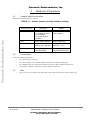
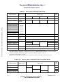
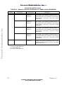
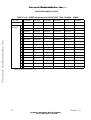
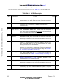
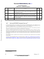
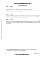
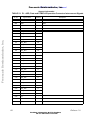
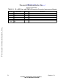
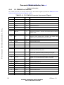
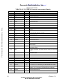
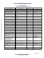
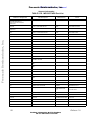
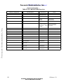
TABLE 4-20. BCSR4 Description
PON
DEF
ATT.
MIIRXEN. When active (high), the MII Fast Ethernet Device Davicom
DM9161E connected to Port D is enabled. When negated (low) all device
output signals are tri- stated.
0
R,W
PORESET
PORESETa. When active (high), PORESET is implemented on the
MPC852TADS. When negated (low), the board is out of Power on Reset.
0
R,W
ETHRST
ETHRST. When active (low), the Ethernet Device Davicom DM9161E gets
reset and being initialized to its Reset value. When inactive, the Ethernet
Device is out of Reset.
1
R,W
BIT
MNEMONIC
Function
5
MIIRXEN
6
7
8-31
Reserved
Not Implemented
-
R,W
a. Not implemented.
4•12
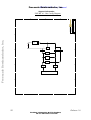
On board EPP/SPP Command ConverterA
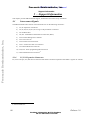
For host-controlled operation, a host computer controls the board via the BDM Debug Port. This configuration serves
for extensive debugging using an on-host debugger. Host computer can be connected with the board directly via On
board Serial command converter or via On board EPP converter. No needs external parts.
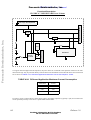
EPP is an asynchronous, byte wide, bidirectional channel controlled by the host device. This interface provides the
capability to send data from the host computer to the MPC852T at a high speed.
The bus is a multiplexed address/data bus connected to a D-Type 25 pins Parallel connector called P20. Typically,
EPP operates on a two-phase-bus cycle. First, an address is generated on the bus and is latched by Altera logic when
the host generates an address strobe. The Altera logic uses this cycle for control. A separate Data strobe is generated
to perform the actual data transfer. Cycles are terminated when the Busy signal is transferred from the Altera to the
host computer.
In the Altera logic there is a parallel to serial converter for write data and a serial to parallel converter for read data
from the MPC.
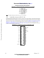
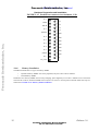
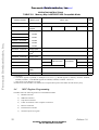
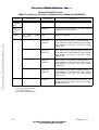
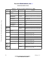
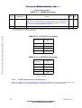
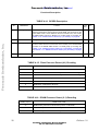
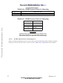
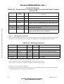
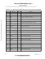
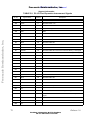
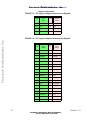
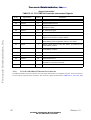
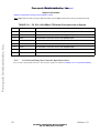
The signals used for EPP Mode transfer are described in detail in TABLE 4-21. "Parallel Host Port Connector’s
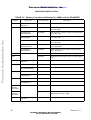
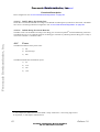
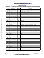
Signal Description with EPP I/F" below . The signals used for Serial Command Converter Mode transfer are described in detail in TABLE 4-22. "Parallel Host Port Connector’s Signal Description with Serial Command
A. For FUTURE Use
59
For More Information On This Product,
Go to: www.freescale.com
Release 1.0