1
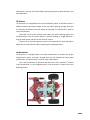
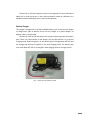
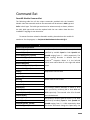
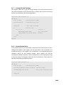
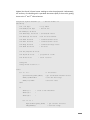
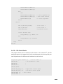
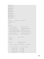
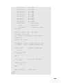
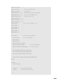
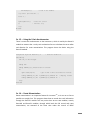
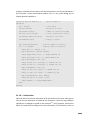
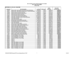
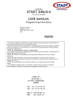
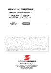
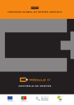
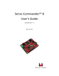
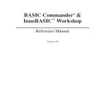
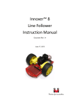
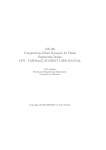
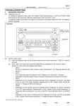
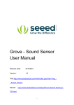
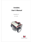
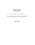
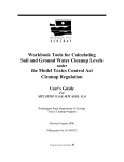
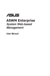
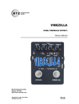
Innoracer
User’s Guide
™
Document Revision 1.5
June 22, 2011
Trademark
Innovati®,
, and BASIC Commander® are registered trademarks of Innovati, Inc.
™
InnoBASIC™, cmdBUS™ and innoracer are trademarks of Innovati, Inc.
Copyright © 2010-2011 by Innovati, Inc. All Rights Reserved.
Due to continual product improvements, Innovati reserves the right to make modifications to its products
without prior notice. Innovati does not recommend the use of its products for application that may present a risk
to human life due to malfunction or otherwise.
No part of this publication may be reproduced or transmitted in any form or by any means without the expressed
written permission of Innovati, Inc.
Disclaimer
Full responsibility for any applications using Innovati products rests firmly with the user and as such Innovati will
not be held responsible for any damages that may occur when using Innovati products. This includes damage to
equipment or property, personal damage to life or health, damage caused by loss of profits, goodwill or otherwise.
Innovati products should not be used for any life saving applications as Innovati’s products are designed for
experimental or prototyping purposes only. Innovati is not responsible for any safety, communication or other
related regulations. It is advised that children under the age of 14 should only conduct experiments under
parental or adult supervision.
Errata
We hope that our users will find this user’s guide a useful, easy to use and interesting publication, as our efforts
to do this have been considerable. Additionally, a substantial amount of effort has been put into this user’s guide
to ensure accuracy and complete and error free content, however it is almost inevitable that certain errors may
have remained undetected. As Innovati will continue to improve the accuracy of its user’s guide, any detected
errors will be published on its website. If you find any errors in the user’s guide please contact us via email
[email protected].
For
the
most
up-to-date
information,
please
visit
our
web
site
at
http://www.innovati.com.tw.
1
Notes:
This package contains a BASIC Commander® module with instruction on how to use it.
Refer to the instructions for the best performance of the item.
When you replace the battery pack or external power supply, make sure the input
voltage is between 6 and 12V to avoid damage to the electronic devices.
There are two DC brush motors, which require a total or 2A current for normal
operation. Insufficient power supply may cause malfunction.
For a longer testing and operating period, you may use external power supply for the
consistent operation performance.
Commands for the built-in modules are available only for innoBASIC™ Workshop
v2.0.2.9 or later.
2
Table of Contents
Product Overview ………………………………………..………….………….……………… 5
Product Features …………………………………………….……………...………….……… 5
System Diagram …………………………………….……….........……...….….…………… 6
Key Components
Controller – BASIC Commander® …………………………………….…….……… 7
Reflective Infrared Sensors ………………………………………...…..……….…… 7
Infrared Sensor Calibration ………….……....……………………….…..………… 8
Buzzer …………………………………………..……………………………………………… 8
DC Motors ………………………………….………….……………..………..….………… 9
Accelerometer ……………………………………….……………..….……………..…… 9
Battery Charger ………………………..……………………………..……………..……10
Command Set
RacerM1 Module Command Set ……………..……….………….…..………….. 11
RacerP1 Module Command Set ………………………..……….…..…..……..… 15
Appendix A --- Tutorial Programs
Ex. 1 --- Light the LEDs Sequentially ………………………………………….….. 21
Ex. 2 --- Light the LEDs If Buttons Pressed ……………………..…..…….….. 21
Ex. 3 --- Motor Control Using RacerM1 ………………..………………..…….. 23
Ex. 4 --- Detection with Infrared Sensors …………..……………..………….. 24
Ex. 5 --- Tracking with 3 Infrared Sensors ……..……………..……………….. 25
Ex. 6 --- Tracking with 7 Infrared Sensors …..………………..……………….. 26
Ex. 7 --- Analog Infrared Readings ……………………………….……………….. 29
3
Ex. 8 --- Normalization Basics …………….………............................…….. 29
Ex. 9 --- Track Detection Using Polynomial Interpolation …….……….. 30
Ex. 10 --- PID Control Basics …….………………………………………….……….. 33
Ex. 11 --- PID Control Using RacerM1 (Digital Mode) ….…….….…….... 36
Ex. 12 --- PID Control Using RacerM1 (Analog Mode) ….……………….. 37
Ex. 13 --- Using the 2-Axis accelerometer………….………….….…………... 39
Ex. 14 --- Route Memorization ………….…………….…………………….…….. 39
Ex. 15 --- Retrieving Route Information ..……......…………………….…….. 41
Ex. 16 --- Acceleration ………………………………………………………..….…….. 42
Appendix B --- Sample Course Map .………………….………………..…….………. 46
Appendix C --- Revision History ……..………………….………………..…….………. 47
4
Product Overview
InnoracerTM is controlled by the BASIC Commander® and featured with two built-in
modules, namely RacerM1 and RacerP1 module. The RacerM1 module is used to
sense the track and control the motors to follow the track. The RacerP1 module is
used to memorize the route by recording the marks on the curve change, which
provides user information to drive the InnoracerTM as fast as possible in later runs. It
is specially designed as an entry-level platform for users to learn programming,
motor control, line tracking with the unique feature of PID control.
Product Features
Using the BASIC Commander® as controller, users can modify their program and
download to the InnoracerTM via a USB cable.
Four cmdBUSTM connectors, which allow users to add peripheral modules easily,
such as Sonar module to enrich the functionality.
7 fixed infrared sensors for track detection.
To fit different track requirement, 2 position-adjustable infrared sensors for start,
stop and curve change marks detection.
Infrared calibration button to optimize the infrared detection range.
Reset button to restart the program.
Variable resistors to change the infrared detection sensitivity, if digital sensor
method is employed.
Four buttons with LEDs for users to define their own functions and indications.
Built-in buzzer controllable through program or used by RacerP1 module to
generate beeps when a curve change mark is detected.
Built-in RacerM1 module to control two DC motors with 1024 steps of speed.
Built-in PID control feature in RacerM1 module for better track following
capability.
Scalar parameter to increase the PID numerical resolution for PID fine tune.
Built-in accelerometer to detect x- and y-axial acceleration forces.
Built-in RacerP1 module to record up to 256 entries of track section information.
Track infrared sensing in digital or analog data with commands for data reading.
Record track information including length, x- and y-axial average and maximum
acceleration value, curve radius and direction.
Hole array on the main board for adjusting the motor position to adapt various
curve tracking needs.
Replacement of motors for better driving performance.
5
System Diagram
Fig 1
System Diagram
Accessories, such as battery, tires or other irrelevant electronic components are
not shown in this system chart.
6
Key Components
Fig 2
Key Component Placement
Controller – BASIC Commander®
BASIC Commander® is the main controller of the InnoracerTM line tracer. Also known
as BC2, the 32-pin version BASIC Commander® has 24 I/O lines suitable for
applications which require more I/O lines.
Users can edit and compile their program in the innoBASICTM Workshop
environment and download through a USB cable to the BASIC Commander®. If you
are not familiar with the BASIC Commander® system, please refer to the “BASIC
Commander® and innoBASICTM Workshop User's Manual” for more detailed
information.
Reflective Infrared Sensors
In the front of the InnoracerTM, there are 7 reflective infrared sensors which are used
to detect the track. The right side infrared sensor is used to detect the Start or Stop
mark, which indicates the beginning and the end of the track. The left side infrared
7
sensor is used to detect the curve change marks throughout the whole route. The
track is divided into segments for route memorization.
Near each infrared sensor, there is a red LED and blue color variant resistor. By
turning the screws on variant resistors, you change the threshold of infrared
detection. The LED will turn on if the reflection intensity is higher than the threshold,
otherwise the LED will turn off. Due to different signal path and threshold settings,
the infrared detection by the BASIC Commander® might not be exactly the same as
that detected by the RacerM1 module.
Please refer to Tutorial Programs section in the appendix for more information
about how to read either digital or analog infrared results.
Infrared Sensors Calibration
Due to the different ambient light and surface material, the infrared sensing results
may vary under different situations. To eliminate the variance, calibration is required.
For the InnoracerTM, there are two kinds of calibration, digital and analog. The
first one is to change the infrared sensors’ detection threshold by adjusting the blue
variant resistor. Turn clock-wise to increase the threshold level, which means the
sensitivity is decreased. Each infrared sensor is accompanied with an LED which will
be lit if the infrared intensity detected is higher than the threshold. Note that this
calibration process only affects the threshold of LEDs and the infrared detection
results read by the BASIC Commander® through its I/Os.
The second one is to press the CAL_BTN button for at least 5 seconds, a red LED
near the CAL_BTN will be lit to indicate the calibration in process. Put the InnoracerTM
on the track and move it back and forth slowly with all the infrared sensors passing
the black and white area of the track several times. Press the CAL_BTN button once
again to finish the calibration process and the LED will turn off. The infrared detection
range of each infrared sensor is measured and normalized internally for analog
infrared intensity sensing use. Note that the analog calibration affects the sensing
results of the RacerM1 module only.
Buzzer
The buzzer is mainly used to generate automatically a 0.2 seconds recording beep
sound each time a curve change mark is detected during the route memorization
process. The buzzer is controlled through the built-in RacerP1 module commands.
Please refer to PacerP1 module command set for other buzzer-related commands.
8
Nevertheless, you may still use the Beep() command to generate beep sounds in your
own application.
DC Motors
The InnoracerTM is equipped with two spur brushed DC motors. A Hall Effect sensor is
affixed to detect the polarity change of the rotor when rotating, through which you
can calculate the distance that each wheel has travelled. This information is used for
route memorization.
Note that the DC motor electric brush wears out when spinning against the
mechanical parts, the DC motors lifetime is limited. Running at a high speed for a
long time will further shorten the life of the DC motors.
Please refer to Tutorial Programs section in the appendix for more information
about how to control the DC motors with the given speed parameters.
Accelerometer
The InnoracerTM is equipped with a two-axial accelerometer to measure the proper
acceleration in both x- and y-axis, through which you can calculate the curve radius
and direction. This information is used for route memorization.
The x-axial acceleration is defined in the lateral axis of the InnoracerTM and the
y-axial acceleration is in the longitudinal axis of the InnoracerTM. Please refer to the
following picture.
Fig 3
Acceleration Directions
9
Please refer to Tutorial Programs section in the appendix for more information
about how to save the current x- and y-axial acceleration values for calibration at a
standstill position and display them in the Terminal Window.
Battery Charger
This charger is designed for 5~10 cells of NiMH battery pack. Do not use this charger
to charge other types of battery. Do not use this charger as a power adaptor. An
adaptor cable is also provided.
Connect the small end of the cable to the charger and the big end to the battery
pack. There is an LED indicator on the charger. The red LED indicates it is in the fast
charging mode. When the green is lit, the battery pack is charged about 85% full and
the charger will continue to operate in the slow charging mode. The battery pack
may reach about 95% full if it is charged in slow charging mode for a longer period.
Fig 4
Battery Charger & Adaptor Cable
10
Command Set
RacerM1 Module Command Set
The following table lists all the unique commands provided with the RacerM1
Module. Note that essential words in the commands will be written in bold type and
italics in bold type. The bold type word must be written exactly as shown, whereas
the italic bold type words must be replaced with the user values. Note that the
innoBASIC™ language is case-insensitive.
To execute functions related to RacerM1 module, please declare the module ID
number as 3 in the program, i.e. Peripheral ModuleName As RacerM1 @ 3
Command Syntax
Description
Motor Control Commands
ForwardA(Speed)
ForwardB(Speed)
ForwardAB(SpeedA, SpeedB)
ForwardDual(Speed)
BackwardA(Speed)
BackwardB(Speed)
BackwardAB(SpeedA, SpeedB)
Sets forward/backward speed of motor A, B or both
specified by variable Speed or both SpeedA and
SpeedB ranging from 0 ~ 1024 respectively. The
motor rotating direction is defined from the
InnoracerTM viewpoint. Motor A is the left-side
wheel motor while Motor B is the right-side wheel
motor.
BackwardDual(Speed)
StopA()
Stops motor A or B or both.
StopB()
StopDual()
BrakeA()
Brakes motor A or B or both.
BrakeB()
BrakeDual()
SetDirA(Dir)
SetDirB(Dir)
SetDirAB(DirA, DirB)
SetDirDual(Dir)
SetDCA(Speed)
SetDCB(Speed)
SetDCAB(SpeedA, SpeedB)
SetDCDual(Speed)
Sets motor(s) rotation direction of motor A, B or
both specified by variable(s) Dir or both DirA and
DirB respectively. The returned value 0 for forward
and 1 for backward.
Sets motor(s) rotation speed of motor A, B or both
specified by variable(s) Speed or both SpeedA and
SpeedB ranging from 0 ~ 1024 respectively. Note
that these commands change the speed only, the
11
direction remains unchanged.
SetVelA(Vel)
Sets speed of motor A, B or both specified by
SetVelB(Vel)
variable Vel or both VelA and VelB ranging from
-1024 ~ 1024 respectively. The absolute value stands
SetVelAB(VelA, VelB)
SetVelDual(Vel)
for speed and positive and negative sign stands for
rotation direction.
Motor Speed and Rotation Direction Commands
GetDCA(Speed)
Gets forward speed of motor A, B or both and stores
GetDCB(Speed)
in variable Speed or both SpeedA and SpeedB. The
returned value(s) ranges from 0 ~ 1024.
GetDCAB(SpeedA, SpeedB)
GetDirA(Dir)
GetDirB(Dir)
GetDirAB(DirA, DirB)
GetVelA(Vel)
GetVelB(Vel)
GetVelAB(VelA, VelB)
Gets rotation direction of motor A, B or both and
stores in variable Dir or both DirA and DirB. The
returned value is 0 for forward and 1 for backward.
Gets speed of motor A, B or both and stores in
variable Vel or both VelA and VelB ranging from
-1024 ~ 1024 respectively. The absolute value stands
for speed and the positive and negative sign stands
for rotation direction.
Infrared Sensing Commands
GetIR(IR)
Gets the digital (1 or 0) values of all seven infrared
sensors, combining in one data byte with value
ranging from 0 ~127 and stores in variable IR. The
bit 0 is the right-most IR sensor and the bit 6 is the
left-most IR sensor. The bit 7 is not used always read
as 0.
GetAnalogIR(ID, IR)
Gets the infrared intensity value ranging from 0
~4095 and stores in variable IR. The infrared sensor
unit is specified by variable ID ranging from 0 ~ 6.
NormStart(Mode)
Sets the normalization calibration mode by the
variable Mode ranging from 0 ~4.
0: Calibrating until calibration button pressed.
1: Calibrating for 10 seconds.
2: Calibrating for 20 seconds.
3: Calibrating for 30 seconds.
4: Calibrating for 60 seconds.
GetNorm (ID, Min, Max)
Gets the minimum and maximum infrared intensity
of specified IR sensor during calibration and stores
them in variable Min and Max, which will be used
12
by the RacerM1 module for internal normalization.
The IR sensor is specified by variable ID ranging
from 0 ~ 6. The infrared intensity value ranges from
0 ~ 4095.
Sets the threshold percentage value specified by
variable Rate ranging from 0 ~ 100 of infrared
intensity range. You can use this setting to change
the infrared sensibility. Take a Rate value 60 for
SetIRThreshold(Rate)
example, if the infrared intensity is stronger than
the 60%, say 85%, of the possible infrared range, it
will be regarded as logic 1 meaning a white track is
detected, otherwise logic 0 meaning white track is
not detected.
GetIRThreshold(Rate)
Retrieves the threshold percentage value and saves
in variable Rate. The value ranges from 0 ~ 100.
Please refer to above command for more details.
SetIRMode(Mode)
Sets the IR sensors track detection method by
variable Mode with value 0 for digital mode or 1 for
analog mode. The default value is 0 for digital mode.
GetIRMode(Mode)
Gets the IR sensors track detection method setting
and stores in variable Mode, of which the value 0 is
for digital mode or 1 for analog mode.
PID Commands
SetP(Val)
SetI(Val)
Sets the P, I or D parameter by variable Val. The
value ranges from 0 ~ 255.
SetD(Val)
GetP(Val)
GetI(Val)
Retrieves the P, I or D parameter and stores in
variable Val. The value ranges from 0 ~ 255.
GetD(Val)
SetScalar(Val)
Sets the PID parameters scalar by variable Val
ranging from0 ~ 32 as a multiple of the original PID
values. However, if the given scalar is greater than
32, the PID control function will not be activated.
GetScalar(Val)
Retrieves the PID Scalar setting and stores in
variable Val ranging from 0 ~ 255. Please refer to
the above command for more details about scalar.
SetErrScale(Err1, Err2, Err3, Err4, Err5, Sets the error values by variables Err1 through Err6
Err6)
as feedback for PID control for various IR detection
13
situations. Each of error value Err1 ~ Err6 ranges
from 0 ~ 127.
Retrieves the error values settings and stores them
GetErrScale (Err1, Err2, Err3, Err4, Err5, in variables Err1 through Err6 as feedback for PID
Err6)
control under various IR detection situations. Each
of Err1 ~ Err6 ranges from 0 ~ 127.
Speed Setting and Control Commands
SetSpdCtrlA(SpdMin, SpdMax)
SetSpdCtrlB(SpdMin, SpdMax)
GetSpdCtrlA(SpdMin, SpdMax)
GetSpdCtrlB(SpdMin, SpdMax)
Sets the minimum and maximum speed of motor A
or B by variables SpdMin and SpdMax for PID speed
control. SpdMin and SpdMax range from -1024 ~
1024. SpdMax must be greater than SpdMin. If the
given value of SpdMax is not greater than SpdMin,
the command will be ignored.
Retrieves the minimum and maximum speed
settings of motor A or B for PID speed control and
stores in variables SpdMin and SpdMax. SpdMin
and SpdMax range from -1024 ~ 1024.
SetStraight(SpeedA, SpeedB)
Sets the straight line speed of motor A and B by
variables SpeedA and SpeedB ranging from -1024 ~
1024 for PID speed control.
GetStraight(SpeedA, SpeedB)
Retrieves the straight line speed setting of motor A
and B and stores in variables SpeedA and SpeedB
ranging from -1024 ~ 1024 for PID speed control.
SpdCtrlOn(Mode)
Starts the PID speed control in mode specified by
variable Mode.
0: Any change of speed settings will terminate the
PID speed control automatically.
1: PID control continues regardless of the speed
settings change.
SpdCtrlOff()
Stops the PID speed control. The InnoracerTM will
run with the last given speed settings.
GetMax(SpeedA, SpeedB)
Gets the maximum speed of motor A and B during
speed control and stores them in SpeedA and
SpeedB, which ranges from -1024 ~ 1024.
GetMin(SpeedA, SpeedB)
Gets the minimum speed of motor A and B during
speed control and stores them in SpeedA and
SpeedB, which ranges from -1024 ~ 1024.
ClearRec()
Clears all the recorded track section information.
14
Sets the speed control frequency by variable Period,
ranging from 0 ~ 100 of unit ms. If the given value
SetCtrlFreq(Period)
exceeds the maximum speed control capability, the
maximum speed will be used. Period with value 0 is
equal to value 1.
Retrieves the speed control frequency setting and
GetCtrlFreq(Period)
stores in variable Period, ranging from 0 ~ 100 of
unit ms.
Miscellaneous Commands
Sets cross road running behavior by variable Mode,
SetCrossMode(Mode)
ranging from 0 ~ 2.
0: keeps running.
1: stops.
2: brakes.
GetCrossMode(Mode)
Retrieves cross road behavior setting and stores in
variable Mode, ranging from 0 ~ 2.
SetOutsideMode(Mode)
Sets the tracer run-away behavior by variable Mode,
ranging from 0 ~ 2.
0: keeps running.
1: stops.
2: brakes.
GetOutsideMode(Mode)
Retrieves the run-away behavior setting and stores
in variable Mode, ranging from 0 ~ 2.
SetLineColor(Color)
Sets the track color by variable Color. Value 0 for
white and 1 for black color. The default value is 0 for
white track color.
GetLineColor(Color)
Retrieves the track color setting and stores in
variable Color. Value 0 for white and 1 for black
color.
RacerP1 Module Command Set
The following table lists all the unique commands provided with the RacerP1 Module.
Note that essential words in the commands will be written in bold type and italics in
bold type. The bold type word must be written exactly as shown, whereas the italic
bold type words must be replaced with the user values. Note that the innoBASIC™
language is case-insensitive.
15
To execute functions related to RacerP1 module, please declare the module ID
number as 4 in the program, i.e. Peripheral ModuleName As RacerP1 @ 4
Command Syntax
Description
Motor Tachometer Commands
bStatus = TACHInR(TACH)
Gets the right or left motor Hall Effect pulse count
detected in each complete 125ms period and stores
it in variable TACH, ranging from 0 ~ 65535 and
returns the pulse counting reading status in variable
bStatus. If the count has not been read, value 1 is
bStatus = TACHInL(TACH)
bStatus = TACHInDual(TACHL, TACHR)
returned, otherwise value 0 is returned.
Note that the count value is stored in an internal
buffer to be read by the commands If you can not
read the count value stored in the buffer within the
125ms interval, the internal data buffer will be
overwritten by the new data.
Gets both the right and left motor Hall Effect pulse
counts detected in each complete 125ms period and
stores them in variable TACHL and TACHR, and
returns the pulse counting status in variable
bStatus, ranging from 0 ~ 3.
0: both of the counts have been read
1: left motor has not been read
2: right motor has not been read
3: both of the counts have not been read
Note that the count values are stored in internal
buffers to be read by the commands separately. If
you cannot read the count value stored in the buffer
within the 125ms interval, both the internal data
buffers will be overwritten by the new data.
Route Recording Commands
StartRec(Mode)
Starts to record the track information. If Mode has
value 1, then the information will be stored in
EEPROM, which can be retrieved later for route
memorization, otherwise, if it has value 0, only
current recorded section information is available,
which will be overwritten by the next track section
information. The recording beep sound at each
16
curve change is generated in both modes.
StopRec()
Stops recording the track information. The recording
beep sound will not be generated.
Gets the track recording status and stores in variable
Status.
GetRecStatus(Status)
0: not recording or recording finished.
1: recording, but has not passed the start mark.
2: recording and passed the start mark.
ClrTotalLen()
Clears the total length of the track in tachometer
counts unit.
GetRateRL(Rate)
Gets the right wheel and left wheel tachometer
pulse count ratio multiplied by 65536 and saves in
variable Rate ranging from 0 ~ 4294967295.
GetSecCnt(Cnt)
Gets the curve change mark counts and stores in
variable Cnt, ranging from 0 ~ 255.
GetSecLen(Num, LengthL, LengthR)
Gets the traveled length of right and left wheel in
section Num, ranging from 0 ~ 255 and stores the
lengths in variable LengthL and LengthR ranging
from 0 ~ 4294967295. The length is expressed with
tachometer counts as the unit.
GetCurSecTACH(LengthL, LengthR)
Gets the traveled length of right and left wheel of
current section and stores the lengths in variable
LengthL and LengthR ranging from 0 ~ 4294967295.
The length is expressed with tachometer counts as
the unit. Note that this command takes effect if
track recording mode is activated.
GetTotalLen(LengthL, LengthR)
Gets the till current total traveled length of right and
left wheel and stores the lengths in variable LengthL
and LengthR ranging from 0 ~ 4294967295. The
length is expressed with tachometer counts as the
unit. Note that this command takes effect if track
recording mode is activated.
Counter Commands
SetTimer(Freq)
Sets the timer time-out frequency by variable Freq,
ranging from 0 ~ 1000 in 10 Hz unit. To start the
timer, a low to high transient needs to be issued by
P12 of BASIC Commander®. When the timer times
out, a high level signal can be issued and can be
17
read from P13 of BASIC Commander®. To clear the
P13 high level signal, a low to high transient needs
to be issued again by P12 of BASIC Commander®.
Retrieves the timer time-out frequency setting and
GetTimer(Freq)
stores in variable Freq, ranging from 0 ~ 1000 in 10
Hz unit.
Infrared Sensing Command
Gets the start/stop and curve change marks detect
result and stores in variable IR ranging from 0 ~ 3,
GetIR(IR)
where bit 0 stands for the start/stop mark and bit 1
for the curve change mark. Take the white marks
for example, if start/stop mark or curve change
mark is detected, their corresponding bit will be 1.
Accelerometer Commands
GetG(Gx, Gy)
Gets x- and y-axial acceleration values ranging from
-2048 ~ 2047 and stores them in variables Gx and
Gy.
GetMaxG(Gx, Gy)
Gets the maximum x- and y-axial acceleration values
ranging from -2048 ~ 2047 and stores them in
variables Gx and Gy. Note that this command takes
effect if track recording mode is activated.
GetAvgG(Gx, Gy)
Gets the average x- and y-axial acceleration values
ranging from -2048 ~ 2047 and stores them in
variables Gx and Gy. Note that this command takes
effect if track recording mode is activated.
GetSecMaxG(Num, Gx, Gy)
Gets the maximum x- and y-axial acceleration values
ranging from -2048 ~ 2047 of route section specified
by variable Num ranging from 0 ~ 255 and stores
them in variables Gx and Gy. Note that this
command takes effect if track recording mode is
activated.
GetSecAvgG(Num, Gx, Gy)
Gets the average x- and y-axial acceleration values
ranging from -2048 ~ 2047 of route section specified
by variable Num ranging from 0 ~ 255 and stores
them in variables Gx and Gy. Note that this
command takes effect if track recording mode is
activated.
SaveCur0G()
Saves current x- and y-axial acceleration values
18
detected as the offsets of a standstill position.
Gets the x- and y-axial acceleration offset values
Load0G(Gx, Gy)
Set0G(Gx, Gy)
stored for standstill position and stores them in
variables Gx and Gy ranging from -2048 ~ 2047.
Sets the x- and y-axial acceleration offset values
for standstill position by variables Gx and Gy ranging
from -2048 ~ 2047.
Curve Commands
Gets the curve direction and radius of the most
recently recorded track section and stores them in
GetRadius(Dir, Radius)
GetSecRadius(Num, Dir, Radius)
variables Dir and Radius. The return value of Dir will
be 0 or 1 which stands for CCW and CW turning
respectively. The value of Radius ranges from 0 ~
4294967295 in tachometer counts unit. Note that
this command takes effect if track recording mode is
activated, otherwise it returns 0.
Gets the curve direction and radius of the track
section specified by variable Num ranging from 0 ~
255, and stores them in variables Dir and Radius.
The return value of Dir will be 0 or 1 which stands
for CCW and CW turning respectively. The value of
Radius ranges from 0 ~ 4294967295 in tachometer
counts unit. If the given section number exceeds the
maximum number of sections, unexpected values
will be returned.
Miscellaneous Commands
Beep()
Generates a beep sound of 0.2 second duration.
AutoBeep(Mode)
Enables or disables Auto Beep function by variable
Mode. When a curve change mark is detected, a 0.2
ms beep sound is generated. Mode with value 0 will
disable auto beep function, while value 1 will
enable the auto beep function. Other values will be
ignored.
SetCrossTime(Time)
Sets the cross track detect interval in variable Time.
If both of the curve and start/stop IR sensors detect
the marks within Time ms interval, it will be
regarded as a cross track instead of a curve or
start/stop mark. Time ranges from 0 ~ 250 ms. It
19
needs to be initialized in the program.
GetCrossTime(Time)
SetLineColor(Color)
Retrieves the cross track detect interval and stores
in variable Time. The value ranges from 0 ~ 250 ms.
Sets the track line color in variable Color. 0: white
line; 1: black line. Other values will be ignored. The
default value is 0 at each program reset.
GetLineColor(Color)
Retrieves the track line color and saves in variable
Color. 0: white line; 1: black line.
Enables or disables EEPROM Write Protection
EnWP()
DisWP()
function. The RacerP1 module uses an on-board
EEPROM to store the recorded information,
including the left and right tachometer counts,
maximum and average acceleration in both x- and
y-direction, curvature radius and direction, etc.
However, this EEPROM is also accessible directly by
the BASIC Commander® through its I/Os. To prevent
from data being over-written accidentally,
commands are provided for EEPROM management.
20
Appendix A --- Tutorial Programs
To help you be familiar with the InnoracerTM, some tutorial programs with brief
introduction are provided in this section. You can also find the tutorial examples in
the DVD.
To maintain the tutorial programs free of error and up-to-date, they are subject
to change without notice. For new users, who are not familiar with the BASIC
Commander®, please refer to the “BASIC Commander® and innoBASICTM Workshop
User's Manual” for more detailed information.
Ex. 1 --- Light the LEDs Sequentially
This program gives the basics of lighting the LEDs. There are 4 LEDs on the
InnoracerTM board, they can be controlled via pin 20, 21, 22 and 23 of the BASIC
Commander® I/Os.
Sub Main()
Dim bLED As Byte
Do
' variable for LED pin number
' infinite do loop
For bLED=20 To 23
' from pin 20 through pin 23
High bLED
' turn on LED
Pause 500
' pause for 0.5 second
Low bLED
' turn off LED
Pause 500
' pause for 0.5 second
Next
Loop
End Sub
Ex. 2 --- Light the LEDs If Buttons Pressed
In addition to the 4 LEDs, there are also 4 buttons on the innoracer® board, they can
be accessed via pin 16, 17, 18 and 19 of the BASIC Commander® I/Os. If any one of
the 4 buttons is pressed, the corresponding LED will be lit.
21
#DEFINE BTN_1 16
#DEFINE BTN_2 17
#DEFINE BTN_3 18
#DEFINE BTN_4 19
Sub Main()
Dim bCnt1 As Byte = 0
Dim bCnt2 As Byte = 0
Dim bCnt3 As Byte = 0
Dim bCnt4 As Byte = 0
BEGIN:
Pause 10
' 10 ms debounce time
' Detect buttons and jump to labels if pressed
Button BTN_1,0,255,20,bCnt1,1,BLINK_LED1
Button BTN_2,0,255,20,bCnt2,1,BLINK_LED2
Button BTN_3,0,255,20,bCnt3,1,BLINK_LED3
Button BTN_4,0,255,20,bCnt4,1,BLINK_LED4
Goto BEGIN
' loop from beginning
BLINK_LED1:
TurnOnLED(20)
Goto BEGIN
BLINK_LED2:
TurnOnLED(21)
Goto BEGIN
BLINK_LED3:
TurnOnLED(22)
Goto BEGIN
BLINK_LED4:
TurnOnLED(23)
Goto BEGIN
End Sub
Sub TurnOnLED(bLED As Byte)
High bLED
' turn on LED
Pause 500
' wait for 0.5 seconds
22
Low bLED
' turn off LED
Pause 500
' wait for 0.5 seconds
End Sub
Ex. 3 --- Motor Control Using RacerM1
There are two DC motors on the innoracer® board. This program gives the basics of
DC motor control using our featured commands available through the RacerM1
module. This program shows how to control the DC motors with the given speed
parameters through the RacerM1 module. To prevent the InnoracerTM from running
away, please keep it off the ground when executing the program.
Note that the DC motor electric brush wears out when spinning against the
mechanical parts, the DC motors lifetime is limited. Running at a high speed for a
long time will further shorten the life of the DC motors.
Peripheral myM As RacerM1 @ 3
' declare Motor Control Module ID
Sub Main()
Dim bKey As Byte
' variable for stop or brake
Dim iVelL, iVelR As Integer
Do
' velocity of left and right motor
' infinite loop
Debug CLS
' clear terminal window
Debugin "Enter Left Motor Speed (-1024~1024): ", iVelL
Debug iVelL, CR
Debugin "Enter Right Motor Speed (-1024~1024): ", iVelR
Debug iVelR, CR
myM.SetVelAB(iVelL, iVelR)
' set parameters to RacerM1 module
Debugin "Enter how to stop (0: Stop, 1: Brake): ", bKey
Debug bKey, CR
If bKey=0 Then
myM.StopDual()
' stop the car
Else
myM.BrakeDual()
' brake the car
End If
23
Keyin "Any key to continue testing", %CHR bKey
Loop
End Sub
Ex. 4 --- Detection with Infrared Sensors
There are total 9 infrared sensors used by the innoracer®. Seven of them are used to
detect the position of the track. The remaining two are used to detect the Start and
Stop mark on the right-hand side and the curve change marks on the left-hand side.
This program shows how to read the infrared detection results and displays them in
the Terminal Window.
Note that the infrared sensors calibration is advised. Please check the "Infrared
Sensors Calibration" section for more details.
Sub Main()
Dim bIR,ST,CH As Byte
Debug
' variables for IR intensity values
CLS
' clear Terminal Window
Debug "Route IR Value: ",CR
' text out to Terminal Window
Debug "
ST IR Value: ",CR
'
Debug "
CH IR Value: "
'
' infinite loop, to detect and show IR intensity values
Do
bIR = Readport(0)
' read port 0 (i.e. bit 0 to bit 7)
bIR = bIR And &H7F
ST=in(11)
' read bit 11
CH=in(7)
Debug CSRXY(17,1), %BIN bIR
' read bit 7
' display bit 0~7 in binary
format
Debug CSRXY(17,2), %BIN ST
Debug CSRXY(17,3), %BIN CH
' display bit 11
' display bit 7
Loop
End Sub
24
Ex. 5 --- Tracking with 3 Infrared Sensors
There are 7 infrared sensors on the InnoracerTM, which can be used to detect the
position of the track. This program starts with an easier way to detect the track by
using the central 3 of them. The ERR values are for tutorial purpose only. You may try
to find your own ERR value as the feedback for better tracking performance.
Peripheral myM As RacerM1 @ 3
' declare module ID
#DEFINE CEN_SPD_R 170
' right wheel central speed
#DEFINE CEN_SPD_L 170
' left wheel central speed
#DEFINE ERR1 80
' error values
#DEFINE ERR2 50
'
#DEFINE ERR3 30
'
#DEFINE ERR4 0
'
#DEFINE ERR5 -30
'
#DEFINE ERR6 -50
'
#DEFINE ERR7 -80
'
Sub Main()
Dim IR2,IR3,IR4,Sensor As Byte
' detection results
Dim R,L,Err As Integer
' right/left speed and error
Pause 2000
Do
' wait for 2 seconds
' infinite Loop
IR2 = In(2)
' read pin 2 (IR2) IR value
IR3 = In(3)
' read pin 3 (IR3) IR value
IR4 = In(4)
' read pin 4 (IR4) IR value
Sensor = (100 * IR4) + (10 * IR3) + IR2
Select Sensor
' error look-up table
Case 011
Err = ERR2
Case 001
Err = ERR3
Case 101
Err = ERR4
Case 100
25
Err = ERR5
Case 110
Err = ERR6
Case 111
If Err<0 Then
' line out of range
Err = ERR7
' set the biggest error
Elseif Err>0 Then
Err = ERR1
' same direction As
' previous error
End If'
Case 000
Err = ERR4
End Select
R = CEN_SPD_R + Err
' adjust right/left
L = CEN_SPD_L - Err
' wheel speed
If R>1024 Then
R = 1024
Elseif R<-1024 Then
R = -1024
' right wheel speed limit
'
'
'
End If
If L>1024 Then
L = 1024
Elseif L<-1024 Then
L = -1024
' left wheel speed limit
'
'
'
End If
myM.SetVelAB(L,R)
' change speed accordingly
Loop
End Sub
Ex. 6 --- Tracking with 7 Infrared Sensors
In this program, we use all of the 7 infrared sensors on the InnoracerTM for tracking,
For smaller curve radius, 3 LEDs might not be enough to follow the track. In this
situation, 7 infrared sensors will be useful. The ERR values are for tutorial purpose
26
only. You may try to find your own ERR value as the feedback for better tracking
performance.
Peripheral myM As RacerM1 @ 3
' declare module ID
#DEFINE CEN_SPD_R 210
' right wheel central speed
#DEFINE CEN_SPD_L 210
' left wheel central speed
#DEFINE ERR1 111
' error values
#DEFINE ERR2 71
#DEFINE ERR3 45
#DEFINE ERR4 21
#DEFINE ERR5 9
#DEFINE ERR6 3
#DEFINE ERR7 0
#DEFINE ERR8 -3
#DEFINE ERR9 -9
#DEFINE ERR10 -21
#DEFINE ERR11 -45
#DEFINE ERR12 -75
#DEFINE ERR13 -111
Sub Stop()
' subroutine to stop motors
myM.BrakeDual()
End Sub
Sub Main()
Dim Sensor As Byte
' detection results
Dim R,L,Err As Integer
' right/left speed and error
Pause 2000
' wait for 2 seconds
Do
' infinite Loop
Sensor=Readport(0)
' read port 0 (P0~P7)
Sensor=Sensor And &H7F
Select Case Sensor
' mask unused P7 data
' error look-up table
Case &B0111111
:
Err = ERR1
Case &B0011111
:
Err = ERR2
Case &B1011111
:
Err = ERR3
27
Case &B1001111
:
Err = ERR4
Case &B1101111
:
Err = ERR5
Case &B1100111
:
Err = ERR6
Case &B1110111
:
Err = ERR7
Case &B1110011
:
Err = ERR8
Case &B1111011
:
Err = ERR9
Case &B1111001
:
Err = ERR10
Case &B1111101
:
Err = ERR11
Case &B1111100
:
Err = ERR12
Case &B1111110
:
Err = ERR13
Case &B1111111
' out of tracking range
Stop()
' stop motors
Goto FINISH
' terminate the program
End Select
R = CEN_SPD_R + Err
' adjust right wheel speed
L = CEN_SPD_L - Err
' adjust left wheel speed
If R>1024 Then
R = 1024
Elseif R<-1024 Then
R = -1024
' right wheel speed limit
'
'
'
End If
'
If L>1024 Then
' left wheel speed limit
L = 1024
Elseif L<-1024 Then
L = -1024
End If
myM.SetVelAB(L,R)
'
'
'
'
' change speed
Loop
FINISH:
End Sub
28
Ex. 7 --- Analog Infrared Readings
This program shows how to get the analog readings of the seven infrared sensors.
They will be displayed in the Terminal Window. It is handy way to check your infrared
sensors if you encounter infrared sensing problem.
Peripheral myM As RacerM1 @ 3
Sub Main()
Dim i As Byte
' Infrared sensor number
Dim wIR As Word
' returned analog value
Debug CLS
' clear Terminal Window
Do
' infinite loop
For i=0 To 6
' from IR 0~6
MyM.GetAnalogIR(i,wIR)
' get analog data
Debug CSRXY(1,i),%DEC6R wIR,CR
' display
Next
Loop
End Sub
Ex. 8 --- Normalization Basics
In the previous exercise, you should have noticed that all the infrared sensors return
readings with different value ranges. The raw data needs to be normalized to be
manipulated easily in the program. The normalization is accomplished during the
calibration process by the RacerM1 module, which employs the min-max
normalization method to perform a linear transformation on the original data range
to new data range. This program shows how the normalization is done within the
RacerM1 module during calibration process.
Peripheral myM As RacerM1 @ 3
Sub Main()
Dim i As Byte
' Infrared sensor number
Dim aMin(6),aMax(6),aSec(6) As Word ' variable arrays
Dim dwIR,dwNorm As Dword
' analog and calibrated values
Debug CLS
29
For i=0 To 6
' from IR 0~6
myM.GetNorm(i,aMin(i),aMax(i))
' get max/min of calibration
aSec(i) = aMax(i) - aMin(i)
' calculate the range
Next
Do
' infinite loop
For i=0 To 6
' from IR 0~6
MyM.GetAnalogIR(i,dwIR)
' get the raw data
dwNorm = (100*(dwIR-aMin(i)))\aSec(i)
' normalization
Debug CSRXY(1,i+1),%DEC7R dwIR
' original values
Debug CSRXY(8,i+1),%DEC7R dwNorm
' normalized values
Next
Loop
End Sub
Ex. 9 --- Track Detection Using Polynomial Interpolation
In the previous “Tracking with 7 Infrared Sensors” exercise, we use the discrete
values, for instance, 1, 2, 3 to describe the location of the track. However, for more
precise PID control, we need higher resolution feedback of the track position. To
achieve this, we employ the polynomial interpolation method in the RacerM1
module. Nevertheless, to learn more about the polynomial interpolation basics, we
implement the polynomial interpolation directly in the main program for tutorial
purposes.
Here we give a brief explanation of how it works. When the InnoracerTM is
running over the track, the infrared reflection intensity detected by the sensors
resembles a normal distribution bell shape. However, the normal distribution
function is not easy to solve, so we use the central part of a parabola to resemble the
normal distribution. The parabola is represented by the polynomial y=ax2+bx+c. From
the infrared readings of 7 IR sensors, we use the 3 highest infrared readings to solve
the polynomial and to get the coefficients a, b and c. The vertex of a parabola
indicates the center of the track, which can be calculated by the formula x=-b/2a with
the highest IR sensor as the origin of the coordinates.
Note that to solve the polynomial we need 3 highest readings, which are more
significant to resemble the actual intensity distribution precisely. However, if the
highest reading comes from the rightmost or leftmost IR sensor, the third highest
reading infrared sensor next to it does not exist. In that case we must take the next
30
highest (the fourth) infrared sensor reading to solve the polynomial. Unfortunately,
the accuracy of resembling with a parabola decreases rapidly if the track is getting
closer to the 1st and 7th infrared sensors.
Peripheral myM As RacerM1 @ 3
' declare module ID
Sub Main()
Dim i As Byte
' loop index
Dim bNum(2) As Byte
' max IR IDs
Dim wARY(13) As Word
Dim dwNorm(6) As Dword
' calibrated values
Dim dwVal(2) As Dword
' max IR value buffer
Dim wMax As Word
' calibrated max value
Dim wMin As Word
' calibrated min value
Dim wRng As Word
' calibrated range value
Dim dwIR As Dword
' IR value
Dim fY1,fY2,fY3 As Float
Dim fA,fB As Float
' polynominal coeff.
Dim fX As Float
' track location
Debug CLS
Debug "Track Position: "
start:
For i=0 To 6
' 7 IR sensors
myM.GetNorm(i,wMin,wMax)
' get calibrated min/max values
wARY(i)=wMax-wMin
' save min-max range
wARY(i+7)=wMin
' save min value
Next
Do
dwVal(0)=0
' clear 3 max IR buffer
dwVal(1)=0
'
dwVal(2)=0
'
For i=0 To 6
MyM.GetAnalogIR(i,dwIR)
' get current IR value
wRng=wARY(i)
' retrieve range
31
wMin=wARY(i+7)
' retrieve min value
dwNorm(i)=(100*(dwIR-wMin))\wRng
If dwNorm(i)>dwVal(0) Then
' normalization
' sort to get the
dwVal(2)=dwVal(1)
' 3 highest normalized
dwVal(1)=dwVal(0)
' IR values and IDs
dwVal(0)=dwNorm(i)
'
bNum(2)=bNum(1)
'
bNum(1)=bNum(0)
'
bNum(0)=i
'
Elseif dwNorm(i)>dwVal(1) Then
'
dwVal(2)=dwVal(1)
'
dwVal(1)=dwNorm(i)
'
bNum(2)=bNum(1)
'
bNum(1)=i
'
Elseif dwNorm(i)>dwVal(2) Then
dwVal(2)=dwNorm(i)
bNum(2)=i
'
'
'
End If
'
Next
'
If bNum(0)=bNum(1)+1 Then
If bNum(0)<6 Then
' track at right side
' highest IR ID 0~5
fX=bNum(0)
fY1=Dword2float(dwVal(1))
fY2=Dword2float(dwVal(0))
fY3=Dword2float(dwNorm(bNum(0)+1))
' take left side IR
Else
fX=5
fY1=Dword2float(dwNorm(4))
' no more leftmost IR
fY2=Dword2float(dwVal(1))
' take 4th IR instead
fY3=Dword2float(dwVal(0))
' to solve polynomial
End If
Elseif bNum(0)=bNum(1)-1 Then
If bNum(0)>0 Then
' track at left side
' highest ID 1~6
fX=bNum(0)
fY1=Dword2float(dwNorm(bNum(0)-1)) ' take right side IR
32
fY2=Dword2float(dwVal(0))
fY3=Dword2float(dwVal(1))
Else
fX=1
fY1=Dword2float(dwVal(0))
' no more rightmost IR
fY2=Dword2float(dwVal(1))
' take 2nd IR instead
fY3=Dword2float(2)
' to solve polynomial
End If
End If
fA=0.5*(fY1+fY3-(2*fY2))
' solve coeff. a
fB=0.5*(fY3-fY1)
' solve coeff. b
fX=fX-fB/(2*fA)
' estimated location
If fX>0 And fX<6 Then
Debug CSRXY(16,1), %REAL1.6 fX
Else
Debug CSRXY(16,1), "OUTSIDE"
End If
Loop
End Sub
Ex. 10 --- PID Control Basics
This program shows how to employ the PID control on the InnoracerTM. The PID
parameters given in this program are just for tutorial purpose only. You may find your
own PID parameters for different track conditions by trial and error.
Peripheral myM As RacerM1 @ 3
' declare module ID
#DEFINE KP 6
' PID parameters (0~255)
#DEFINE KI 0
'
#DEFINE KD 40
'
#DEFINE SCALE 0
#DEFINE CEN_SPD_R 210
' right wheel central speed
#DEFINE CEN_SPD_L 210
' left wheel central speed
#DEFINE ERR1 111
' error values
#DEFINE ERR2 71
33
#DEFINE ERR3 45
#DEFINE ERR4 21
#DEFINE ERR5 9
#DEFINE ERR6 3
#DEFINE ERR7 0
#DEFINE ERR8 -3
#DEFINE ERR9 -9
#DEFINE ERR10 -21
#DEFINE ERR11 -45
#DEFINE ERR12 -75
#DEFINE ERR13 -111
Sub Stop()
' subroutine to stop motors
myM.BrakeDual()
End Sub
Sub Main()
Dim Sensor As Byte
' detection results
Dim R, L As Integer
' right/left wheel speed
Dim Integral As Integer
' Integral of errors
Dim Derivative As Integer
' derivative of errors
Dim Err, PreErr As Integer
' error and previous error
Dim Out As Integer
' result of PID calculation
Dim Control As Integer
' PID control values
Out = 0
' initial values
Integral = 0
'
PreErr = 0
'
Pause 1000
' wait for one second
Do
' infinite Loop
Sensor = Readport(0) And &B01111111
Select Case Sensor
' read port 0
' error look-up table
Case &B0111111
:
Err = ERR1
Case &B0011111
:
Err = ERR2
Case &B1011111
:
Err = ERR3
Case &B1001111
:
Err = ERR4
34
Case &B1101111
:
Err = ERR5
Case &B1100111
:
Err = ERR6
Case &B1110111
:
Err = ERR7
Case &B1110011
:
Err = ERR8
Case &B1111011
:
Err = ERR9
Case &B1111001
:
Err = ERR10
Case &B1111101
:
Err = ERR11
Case &B1111100
:
Err = ERR12
Case &B1111110
:
Err = ERR13
Case &B1111111
' out of range
Stop()
' stop motors
Goto FINISH
' terminate the program
End Select
Integral = Integral + Err
'PID formula
Derivative = Err - PreErr
Out = (KP*Err) + (KI*Integral) + (KD*Derivative)
PreErr = Err
Control = Out >> SCALE
R = CEN_SPD_R + Control ' adjust right wheel speed
L = CEN_SPD_L - Control ' adjust left wheel speed
If R>1024 Then
R = 1024
Elseif R<-1024 Then
R = -1024
' right wheel speed limit
'
'
'
End If
If L>1024 Then
L = 1024
Elseif L<-1024 Then
L = -1024
' left wheel speed limit
'
'
'
End If
myM.SetVelAB(L,R)
' change speed
Loop
FINISH:
35
End Sub
Ex. 11 --- PID Control Using RacerM1 (Digital Mode)
We practice the PID control in the precious program and now we start to use the
unique built-in PID control feature of the RacerM1 module. The major advantage that
we can get in using the RacerM1 module is to save our valuable BASIC Commander®
time to handle other important tasks.
There are two modes available, one is the digital mode, which interprets all the
infrared reflection intensity values as logic 0 or 1 and the other is the analog mode,
which interprets all the infrared reflection intensity values as analog values with
wider range. Let’s start with the digital mode first.
Peripheral myM1 As RacerM1 @ 3
' declare module ID
#DEFINE KP 6
' set PID parameters (0~255)
#DEFINE KI 0
'
#DEFINE KD 40
'
#DEFINE PID_SCALE 0
#DEFINE IR_POWER 70
' define IR threshold
#DEFINE MAX_SPD_L 1024
' max/min/central speed settings
#DEFINE MAX_SPD_R 1024
' for left and right motors
#DEFINE CEN_SPD_L 210
' ranging -1024~1024
#DEFINE CEN_SPD_R 210
'
#DEFINE MIN_SPD_L -1024 '
#DEFINE MIN_SPD_R -1024 '
#DEFINE ERR1 10
' error values ranging 0~127
#DEFINE ERR2 20
'
#DEFINE ERR3 32
'
#DEFINE ERR4 45
'
#DEFINE ERR5 70
'
#DEFINE ERR6 90
'
Sub InitM1()
' initialize M1 parameters
myM1.SetP(KP)
myM1.SetI(KI)
36
myM1.SetD(KD)
myM1.SetScalar(PID_SCALE)
myM1.SetIRThreshold(IR_POWER)
myM1.SetSpdCtrlA(MIN_SPD_L,MAX_SPD_L)
myM1.SetSpdCtrlB(MIN_SPD_R,MAX_SPD_R)
myM1.SetStraight(CEN_SPD_L,CEN_SPD_R)
myM1.SetErrScale(ERR1,ERR2,ERR3,ERR4,ERR5,ERR6)
End Sub
Sub Main()
Dim bIr AS BYTE
Debug CLS
' clear Terminal Window
InitM1()
' initialize M1 parameters
Do
bIr=Readport(0)
' track in the middle?
Loop Until (bIr And &B1000)
Pause 3000
' wait for 3 seconds
myM1.SpdCtrlOn(0)
' start PID control
Do
' infinite Loop
Loop
End Sub
Ex. 12 --- PID Control Using RacerM1 (Analog Mode)
As mentioned in the previous practice, there are two modes available, one is the
digital mode, which interprets all the infrared reflection intensity values as logic 0 or
1 and the other is the analog mode, which interprets all the infrared reflection
intensity values as analog values with wider range. Now we try the analog mode,
which has a better resolution in locating the track. Let’s check it out!
Peripheral myM1 As RacerM1 @ 3
' declare module ID
#DEFINE KP 6
' set PID parameters (0~255)
#DEFINE KI 0
'
#DEFINE KD 40
'
37
#DEFINE PID_SCALE 0
'
#DEFINE IR_MODE 1
' analog IR sensing mode
#DEFINE IR_POWER 70
' IR intensity
#DEFINE MAX_SPD_L 1024 ' max/min/central speed settings
#DEFINE MAX_SPD_R 1024 ' for left and right motors
#DEFINE CEN_SPD_L 210
' ranging -1024~1024
#DEFINE CEN_SPD_R 210
'
#DEFINE MIN_SPD_L -1024 '
#DEFINE MIN_SPD_R -1024 '
#DEFINE ERR1 3
' error values ranging 0~127
#DEFINE ERR2 9
'
#DEFINE ERR3 21
'
#DEFINE ERR4 45
'
#DEFINE ERR5 71
'
#DEFINE ERR6 111
'
Sub InitM1()
' initialize M1 parameters
myM1.SetP(KP)
' set PID parameters
myM1.SetI(KI)
'
myM1.SetD(KD)
'
myM1.SetScalar(PID_SCALE)
myM1.SetIRMode(IR_MODE)
' set IR sensing mode
myM1.SetIRThreshold(IR_POWER)
' set IR threshold
myM1.SetSpdCtrlA(MIN_SPD_L,MAX_SPD_L)
myM1.SetSpdCtrlB(MIN_SPD_R,MAX_SPD_R)
myM1.SetStraight(CEN_SPD_L,CEN_SPD_R)
myM1.SetErrScale(ERR1,ERR2,ERR3,ERR4,ERR5,ERR6)
End Sub
Sub Main()
Dim bIr AS BYTE
Debug CLS
' clear Terminal Window
InitM1()
' initialize M1 parameters
Do
38
bIr=Readport(0)
' track in the middle?
Loop Until (bIr And &B1000)
Pause 3000
myM1.SpdCtrlOn(0)
' start PID control
Do
' infinite loop
Loop
End Sub
Ex. 13 --- Using the 2-Axis Accelerometer
There is a two-axis accelerometer on the InnoracerTM, which is used by the RacerP1
module to measure the x- and y-axis acceleration force to calculate the curve radius
and direction for route memorization. This program shows the basics using the
RacerP1 module.
Peripheral myP1 As RacerP1 @ 4
' declare module ID
Sub Main()
Dim iX, iY As Integer
Debug CLS
Debug CSRXY(1,1),"Acceleration values"
Do
myP1.GetG(iX,iY)
' get X and Y axis acceleration values
Debug CSRXY(1,2),"X: ",CSRXY(4,2),%DEC5R iX
' display values
Debug CSRXY(1,3),"Y: ",CSRXY(4,3),%DEC5R iY
'
Loop
End Sub
Ex. 14 --- Route Memorization
Route memorization is an important feature for InnoracerTM, so it can run as fast as
possible on straight line. This program shows how to record the track information
through the RacerP1 module. You may notice that we use two modules, namely
RacerM1 and RacerP1 modules, through which both the PID control and route
memorization, are executed at the same time under the control of BASIC
39
Commander®.
Peripheral myM1 As RacerM1 @ 3
' declare module ID
Peripheral myP1 As RacerP1 @ 4
'
#DEFINE CROSS_TIME 20
' time to detect intersection
#DEFINE KP 4
' set PID parameters (0~255)
#DEFINE KI 0
'
#DEFINE KD 40
'
#DEFINE PID_SCALE 0
'
#DEFINE MAX_SPD_L 1024
' max/min/central speed settings
#DEFINE MAX_SPD_R 1024
' for left and right motors
#DEFINE CEN_SPD_L 210
' ranging -1024~1024
#DEFINE CEN_SPD_R 210
'
#DEFINE MIN_SPD_L -1024 '
#DEFINE MIN_SPD_R -1024 '
#DEFINE ERR1 10
' error values ranging 0~127
#DEFINE ERR2 20
'
#DEFINE ERR3 32
'
#DEFINE ERR4 45
'
#DEFINE ERR5 70
'
#DEFINE ERR6 90
'
Sub InitM1()
' initialize M1 parameters
myM1.SetP(KP)
' set PID parameters
myM1.SetI(KI)
myM1.SetD(KD)
myM1.SetScalar(PID_SCALE)
myM1.SetSpdCtrlA(MIN_SPD_L,MAX_SPD_L)
myM1.SetSpdCtrlB(MIN_SPD_R,MAX_SPD_R)
myM1.SetStraight(CEN_SPD_L,CEN_SPD_R)
myM1.SetErrScale(ERR1,ERR2,ERR3,ERR4,ERR5,ERR6)
End Sub
Sub InitP1()
' initialize P1 parameters
40
myP1.SetCrossTime(CROSS_TIME)
' set detection time
myP1.AutoBeep(1)
' recording beeps on
End Sub
Sub Main()
Dim Status As Byte
Dim bIR As Byte
InitM1()
' initialize M1 parameters
InitP1()
' initialize P1 parameters
Do
myM1.GetIR(bIr)
' track in the middle?
Loop Until (bIR And &B1000)
myP1.StartRec(1)
' start recording
Do
myP1.GetRecStatus(Status)
' recording started?
Loop Until Status=1
myM1.SpdCtrlOn(0)
' start PID control
Do
myP1.GetRecStatus(Status)
' start mark detected?
Loop Until Status=2
Do
myP1.GetRecStatus(Status)
' stop mark detected?
Loop Until Status=0
myP1.StopRec()
myM1.BrakeDual()
' stop recording
' brake both wheels
End Sub
Ex. 15 --- Retrieving Route Information
In previous exercise, we recorded all the sections of route information. In this
41
program, we display all the sections of route information in the Terminal Window. If
you encounter a route memorization problem, this is a very useful debug tool to
identify where the problem is.
Peripheral myP1 As RacerP1 @ 4
' declare module ID
Sub Main()
Dim i As Byte
' route index
Dim bDir As Byte
' direction of curve
Dim bSecCnt As Byte
' number of sections recorded
Dim iGx, iGy As Integer
' x and y acceleration values
Dim dwLenR, dwLenL As Dword
' distance of sections
Dim dwRad As Dword
' radius of curves
myP1.GetSecCnt(bSecCnt)
' read the number of sections
For i=0 To bSecCnt
' display section information
Debug "Sec.: ", %DEC3R i, CR
myP1.GetSecLen(i, dwLenL, dwLenR)
Debug "Right Wheel Dist.: ", %DEC9R dwLenR, CR
Debug "Left Wheel Dist.: ", %DEC9R dwLenL, CR
myP1.GetSecAvgG(i, iGx, iGy)
Debug "X-axis acc. (average): ", %DEC5R iGx, CR
Debug "Y-axis acc. (average): ", %DEC5R iGy, CR
myP1.GetSecMaxG(i, iGx, iGy)
Debug " X-axis acc. (max.): ", %DEC5R iGx, CR
Debug " Y-axis acc. (max.): ", %DEC5R iGy, CR
myP1.GetSecRadius(i, bDir, dwRad)
Debug "Direction of curve: ", bDir
Debug "Radius: ", %DEC9R dwRad,CR,CR
Next
End Sub
Ex. 16 --- Acceleration
We know how to record the information of all the sections of the route. Now we can
start to use this information to speed up our InnoracerTM. There are many different
approaches or strategies to speed up the InnoracerTM. In this program, we learn the
basics of acceleration according to the route information. The InnoracerTM starts to
42
accelerate after the Start mark is detected and stops after a given distance is
reached.
Peripheral myM1 As RacerM1 @ 3
' declare module ID
Peripheral myP1 As RacerP1 @ 4
'
#DEFINE CROSS_TIME 20
' time to detect intersection
#DEFINE KP 4
' set PID parameters (0~255)
#DEFINE KI 0
'
#DEFINE KD 48
'
#DEFINE PID_SCALE 0
'
#DEFINE MAX_SPD_L 1024
' max/min/central/acc speed settings
#DEFINE MAX_SPD_R 1024
' for left and right motors
#DEFINE CEN_SPD_L 210
' ranging -1024~1024
#DEFINE CEN_SPD_R 210
'
#DEFINE MIN_SPD_L -1024 '
#DEFINE MIN_SPD_R -1024 '
#DEFINE ACC_SPD_L 450
'
#DEFINE ACC_SPD_R 450
'
#DEFINE STOP_TACH 100
' distance before start to brake
#DEFINE ERR1 10
' error values ranging 0~127
#DEFINE ERR2 20
'
#DEFINE ERR3 32
'
#DEFINE ERR4 45
'
#DEFINE ERR5 70
'
#DEFINE ERR6 90
'
Sub InitM1()
' M1 module initialization
myM1.SetOutsideMode(2)
myM1.SetP(KP)
' set out-of-track behavior
' set PID parameters
myM1.SetI(KI)
myM1.SetD(KD)
myM1.SetScalar(PID_SCALE)
myM1.SetSpdCtrlA(MIN_SPD_L,MAX_SPD_L)
myM1.SetSpdCtrlB(MIN_SPD_R,MAX_SPD_R)
myM1.SetStraight(CEN_SPD_L,CEN_SPD_R)
43
myM1.SetErrScale(ERR1,ERR2,ERR3,ERR4,ERR5,ERR6)
End Sub
Sub InitP1()
' P1 module initialization
myP1.SetCrossTime(CROSS_TIME)
' set detection time
End Sub
Sub Main()
Dim Status As Byte
Dim IR As Byte
Dim bCnt1 As Word
Dim LenR,LenL As Word
bCnt1 =0
InitM1()
'initialize M1
InitP1()
'initialize P1
WAIT_BUTTON:
Do
Button(16,0,255,255,bCnt1,1,RACE) ' button pressed?
Loop
RACE:
Do
myM1.GetIR(IR)
' track in the middle?
Loop Until (IR And &B1000)
Pause 2000
myP1.StartRec(0)
' start recording
Do
myP1.GetRecStatus(Status) ' recording started?
Loop Until Status=1
myM1.SpdCtrlOn(0)
' start PID control
Do
myP1.GetRecStatus(Status) ' start mark detected?
Loop Until Status=2
myM1.SetStraight(ACC_SPD_L,ACC_SPD_R)
' high speed
44
Do
myP1.GetTotalLen(LenL,LenR)
Loop Until LenL>STOP_TACH
myM1.BrakeDual()
' brake
myP1.StopRec()
' stop recording
Goto WAIT_BUTTON
End Sub
45
Appendix B --- Sample Course Map
This is a sample track. The actual size is 150 cm x 230 cm. There could be different
racing games with similar rules. Please refer to their official document and modify
the course and program accordingly.
46
Appendix C --- Revision History
Revision
Date
Changes
1.4
Jan. 16, 2011
New Release (English Edition)
1.5
June 22, 2011
1. Correct Command Format Description Error:
bStatus = TACHInDual(TACHL, TACHR)
GetSecLen(Num, LengthL, LengthR)
GetCurSecTACH(LengthL, LengthR)
GetTotalLen(LengthL, LengthR)
2. Related Correction in Tutorial Ex 15 and Ex16.
47