1
Courtesy of Steven Engineering, Inc. Ÿ 230 Ryan Way, South San Francisco, CA, 94080-6370 Ÿ Main Office: (650) 588-9200 Ÿ Outside Local Area: (800) 258-9200 Ÿ www.stevenengineering.com
User Manual
QUICKMARQUEE
By Total Control Products, Inc.
QUICKMARQUEE
QUICKMARQUEE DISPLAY User Manual
800-0300-013
Revision B
Courtesy of Steven Engineering, Inc. Ÿ 230 Ryan Way, South San Francisco, CA, 94080-6370 Ÿ Main Office: (650) 588-9200 Ÿ Outside Local Area: (800) 258-9200 Ÿ www.stevenengineering.com
This manual was produced by the QUICKMARQUEE team of Total Control Products, Inc., Melrose Park, Illinois.
Copyright 1993, Total Control Products, Inc. All rights reserved.
Manual Design and Implementation by: Patrick Ward
The following are trademarks of Total Control Products, Inc.: SMART SCREEN, SMART MC, SMART AT, SMART
VT, SMART PANEL, SMART PANEL Plus, SMART TOUCH, QUICKMARQUEE, QUICKPANEL, and
QUICKPANEL Plus.
Windows is a trademark of Microsoft Corporation.
Information in this document is subject to change without notice and does not represent a commitment on the part of
Total Control Products, Inc. The software described in this document is provided under a license agreement. The
software may be used or copied only under the terms of the agreement. Only one copy of the software may be made for a
backup.
Total Control Products, Inc. makes no warranty, either expressed or implied, including but not limited to any implied
warranties of merchantability or fitness for a particular purpose, regarding these materials and makes such materials
available solely on an "as-is" basis.
In no event shall Total Control Products, Inc. be liable to anyone for special, collateral, incidental, or consequential
damages in connection with or arising out of purchase or use of these materials. The sole and exclusive liability to Total
Control Products, Inc., regardless of the form of action, shall not exceed the purchase price of the materials described
herein.
No part of this manual may be reproduced or transmitted in any form or by any means, electronic or mechanical,
including photocopying, recording, or information storage and retrieval systems, for any purpose other than the
purchaser's personal use, without the express written permission of Total Control Products, Inc.
The following logo is registered to Total Control Products, Inc.
"Operator Interface Specialists"
2001 N. Janice Ave., Melrose Park, IL 60160 USA
Phone (708) 345-5500 FAX (708) 345-5670
Courtesy of Steven Engineering, Inc. Ÿ 230 Ryan Way, South San Francisco, CA, 94080-6370 Ÿ Main Office: (650) 588-9200 Ÿ Outside Local Area: (800) 258-9200 Ÿ www.stevenengineering.com
Contents
1. INTRODUCTION
1
1.1. INTRODUCTION ..............................................................................................................1
1.2. DISPLAY CONFIGURATIONS ........................................................................................2
1.3. DIMENSIONS ....................................................................................................................3
1.4. SPECIFICATIONS .............................................................................................................4
1.5. OPERATING TEMPERATURE ........................................................................................5
1.6. UNPACKING .....................................................................................................................6
2. INSTALLATION
7
2.1. INSTALLATION................................................................................................................7
2.2. MECHANICAL MOUNTING............................................................................................7
2.3. MARQUEE DISPLAY MOUNTING HOLE .....................................................................8
2.4. HANGING/WALL MOUNTING BRACKET....................................................................8
2.5. CHAIN SUSPENSION .......................................................................................................9
2.6. WALL MOUNTING.........................................................................................................10
2.7. BACK TO BACK MOUNTING BRACKET ...................................................................11
2.8. MULTIPLE UNIT BRACKETS.......................................................................................12
2.9. ADJUSTABLE GLARE VISOR ......................................................................................13
2.10. POWER CABLE/COMMUNICATIONS CABLE ACCESS PLATE............................14
3. ELECTRICAL
15
3.1. GROUNDING...................................................................................................................15
3.2. WIRE RUNS AND WIRING............................................................................................15
3.3. ELECTRICAL CONNECTIONS .....................................................................................15
3.4. CONNECTING AC POWER (TERMINALS L, G, N) ....................................................16
3.5. SERIAL COMMUNICATION (TERMINALS 1-7).........................................................16
3.6. RS232 CONNECTIONS (TERMINALS 1-3) ..................................................................16
3.7. RS422/485 CONNECTIONS............................................................................................17
3.8. OPEN COLLECTOR OUTPUT .......................................................................................18
3.9. DISPLAY CONFIGURATION (Switch A) ......................................................................18
3.10. BAUD RATE SELECTION (Switch A) .........................................................................19
3.11. CHARACTER SIZE SELECTION (Switch A) ..............................................................20
3.12. PROTOCOL SELECTION (Switch A)...........................................................................21
3.13. SELF TEST SELECTION (Switch A)............................................................................21
3.14. ADDRESS SELECTION (Switch B)..............................................................................22
3.15. FINAL CHECKS ............................................................................................................22
4. COMMUNICATION
25
4.1. INTRODUCTION ............................................................................................................25
4.2. SLAVE PROTOCOL FORMAT ......................................................................................26
4.3. FIELD 1 - HEADER CONTROL CHARACTERS FOR AUTO REPEAT......................27
4.3.1. AUTO REPEAT - TEXT FIELD FORMAT ...................................................28
TOTAL CONTROL
i
Courtesy of Steven Engineering, Inc. Ÿ 230 Ryan Way, South San Francisco, CA, 94080-6370 Ÿ Main Office: (650) 588-9200 Ÿ Outside Local Area: (800) 258-9200 Ÿ www.stevenengineering.com
4.3.2. AUTO REPEAT - TEXT FIELD VARIABLE............................................... 30
4.4. FIELD 2 - DISPLAYABLE CHARACTER FIELD ........................................................ 31
4.5. FIELD 3 - OPTIONAL TRAILER CONTROL CHARACTER ...................................... 32
4.6. FIELD 4 - DEVICE ADDRESS....................................................................................... 33
4.7. FIELD 5 - LINE NUMBER ............................................................................................. 34
4.8. FIELD 6 - CARRIAGE RETURN ................................................................................... 35
4.9. EXAMPLES..................................................................................................................... 35
4.9.1. STANDARD FORMAT MESSAGES............................................................ 35
4.9.2. AUTO REPEAT MESSAGES........................................................................ 36
5. APPLICATIONS
39
5.1. HOST DEVICES.............................................................................................................. 39
5.2. HOST COMPUTER......................................................................................................... 40
5.3. MARQUEE CONTROLLER ........................................................................................... 41
5.4. ALLEN-BRADLEY DL20 & DL40 COMPATIBILITY ................................................ 41
5.5. SMART SIM & SMART MC COMPATIBILITY .......................................................... 42
6. MAINTENANCE
45
6.1. CLEANING THE LENS.................................................................................................. 45
6.2. FACTORY REPAIRS ...................................................................................................... 45
ii
TOTAL CONTROL
Courtesy of Steven Engineering, Inc. Ÿ 230 Ryan Way, South San Francisco, CA, 94080-6370 Ÿ Main Office: (650) 588-9200 Ÿ Outside Local Area: (800) 258-9200 Ÿ www.stevenengineering.com
1. INTRODUCTION
1.1. INTRODUCTION
Marquee Displays can display alphanumeric messages received from a host. The
host may be a Marquee Controller (SM1000SMC), programmable logic controller,
computer, or a master Allen-Bradley Bulletin 2706 Dataliner DL20 display. Either
RS232 or RS422/485 (multidrop) serial communication can be used. All message
attributes and storage of messages is performed by the host.
Marquee Displays operate in a Slave mode. The slave mode allows up to 123
displays to have a unique address when using an RS422 network. Also, RS232 can
be used. Serial commands are described later in this manual.
QUICKMARQUEE DISPLAY
1
Courtesy of Steven Engineering, Inc. Ÿ 230 Ryan Way, South San Francisco, CA, 94080-6370 Ÿ Main Office: (650) 588-9200 Ÿ Outside Local Area: (800) 258-9200 Ÿ www.stevenengineering.com
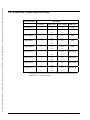
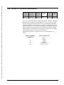
1.2. DISPLAY CONFIGURATIONS
Catalog Number
Description
# of Lines
Chars./Line
Char. Height
LED Color
SM1202FOA
1
20
2"
RED
QM1104ROA *
1
10
4.8"
RED
2
20
2.1"
1
20
4.8"
2
40
2.1"
2
20
4.8"
4
40
2.1"
4
20
4.8"
8
40
2.1"
1
10
4.8"
2
20
2.1"
1
20
4.8"
2
40
2.1"
2
20
4.8"
4
40
2.1"
4
20
4.8"
8
40
2.1"
QM1204ROA *
QM2204ROA *
QM4204ROA *
QM1104COA *
QM1204COA *
QM2204COA *
QM4204COA *
RED
RED
RED
TRICOLOR
TRICOLOR
TRICOLOR
TRICOLOR
* Displays capable of 4.8" characters are also capable of twice as many lines and
characters in a 2.1" character height.
2
QUICKMARQUEE DISPLAY
Courtesy of Steven Engineering, Inc. Ÿ 230 Ryan Way, South San Francisco, CA, 94080-6370 Ÿ Main Office: (650) 588-9200 Ÿ Outside Local Area: (800) 258-9200 Ÿ www.stevenengineering.com
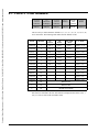
1.3. DIMENSIONS
3/8
DIA.
H
E
I
G
H
T
WIDTH
DEPTH
ADJUSTABLE 1 3/4 TO 2 1/2
Model
Height
(inches)
Width
(inches)
Depth
(inches)
Weight
(lbs)
Power
Required
SM1202FOA
7-7/8
40-1/4
5-5/8
45
60 VA
QM1104ROA
8-1/4
45-1/2
5-1/2
50
100 VA
QM1204ROA
8-1/4
81-1/2
5-1/2
70
150 VA
QM2204ROA
15-1/8
81-1/2
5-1/2
100
300 VA
QM4204ROA
30-1/4
81-1/2
5-1/2
200
600 VA
QM1104COA
8-1/4
45-1/2
5-1/2
50
150 VA
QM1204COA
8-1/4
81-1/2
5-1/2
70
250 VA
QM2204COA
15-1/8
81-1/2
5-1/2
100
500 VA
QM4204COA
30-1/4
81-1/2
5-1/2
200
1000 VA
QUICKMARQUEE DISPLAY
3
Courtesy of Steven Engineering, Inc. Ÿ 230 Ryan Way, South San Francisco, CA, 94080-6370 Ÿ Main Office: (650) 588-9200 Ÿ Outside Local Area: (800) 258-9200 Ÿ www.stevenengineering.com
1.4. SPECIFICATIONS
DISPLAY MEDIA
Type:
Contiguous LED matrix
Color:
Red or Tricolor (red, green & amber)
Viewing Range:
125 ft for 2.1" characters
275 ft for 4.8" characters
Viewing Angle:
60° left/right/up/down
Display Life:
50,000 Hours
ELECTRICAL
Input Voltage:
115 VAC +/- 10%, 60 Hz
Input Power:
See table above.
Fuse Type:
3AG, See table above for rating.
Open-Collector Output: 5 to 24 VDC, 250ma, sinking
Communication:
RS232, RS422/485 (Addressable)
Baud Rate:
300, 1200, 9600, 19200
ENVIRONMENTAL
Operating Temperature: 0° to 55° C
Storage Temperature:
4
-40° to 85° C
Humidity:
5% to 95% non-condensing
Enclosure Type:
NEMA 12/4
QUICKMARQUEE DISPLAY
Courtesy of Steven Engineering, Inc. Ÿ 230 Ryan Way, South San Francisco, CA, 94080-6370 Ÿ Main Office: (650) 588-9200 Ÿ Outside Local Area: (800) 258-9200 Ÿ www.stevenengineering.com
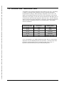
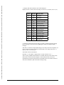
1.5. OPERATING TEMPERATURE
As listed above, the operating temperature of the display is 0° to 55° C. The display
is capable of operating at these temperatures because of thermal management
incorporated into its design. When operating at temperatures close to 55° C, the
display will automatically dim itself to prevent it from overheating. If the internal
temperature of the display exceeds 70°C, the unit will shut down and display OT at 5
second intervals until the internal temperature falls below 68°C. Since the dimming
feature is based on the internal temperature of the display, the ambient temperature at
which each stage of dimming occurs may vary between models. The dimming
criteria is listed below.
Internal Temp. (°°C)
Percent On
Dimming Effect
0 - 49
100%
None
50 -59
75%
Slight
60 - 64
50%
Noticeable
65 - 69
25%
Significant
70+
0%
Display “OT” only
At 75%, the dimming is very slight and hardly noticeable, however, as the internal
temperature rises, the dimming becomes more noticeable. As the unit cools down,
the display will automatically increase its brightness until back to 100%. A
hysteresis is built into this feature to prevent any flickering effect.
QUICKMARQUEE DISPLAY
5
Courtesy of Steven Engineering, Inc. Ÿ 230 Ryan Way, South San Francisco, CA, 94080-6370 Ÿ Main Office: (650) 588-9200 Ÿ Outside Local Area: (800) 258-9200 Ÿ www.stevenengineering.com
1.6. UNPACKING
No special precautions, other than careful handling, are required during unpacking
the display. Care should be taken to avoid scratching the lens on the front panel.
6
QUICKMARQUEE DISPLAY
Courtesy of Steven Engineering, Inc. Ÿ 230 Ryan Way, South San Francisco, CA, 94080-6370 Ÿ Main Office: (650) 588-9200 Ÿ Outside Local Area: (800) 258-9200 Ÿ www.stevenengineering.com
2. INSTALLATION
2.1. INSTALLATION
Marquee Displays are fully inspected and tested before leaving the factory. They are
packed in specially designed cartons to protect them from damage during shipment.
They should, however, be inspected upon receipt at the destination for visible or
concealed damage. Claims for loss or damage should be filed with the carrier
immediately. A claim for concealed damage is required when damage is not
externally visible. Total Control Products will assist insofar as is practical in securing
satisfactory adjustment of claims; however, all claims for loss and damage must be
made by the purchaser to the carrier.
In the application of Total Control Products Marquee Displays, every precaution
must be taken to provide a safe mechanical support system and proper electrical
components for a safe electrical system. Local codes and ordinances governing
wiring and installation practices must be observed.
In order to install your Marquee Display you must:
1. Survey the area where the display will be installed. Make sure that sunlight will
not fall directly on the display surface since the LED characters will be washed out
by direct sunlight. While the unit is rated as NEMA 12, it was not designed for
continuous use under dripping liquids such as water pipes, condensation lines, or roof
leaks.
2. Locate a source of 115VAC power and determine how you will route the power to
the Marquee Display. Check the specifications tables for power requirements.
3. Decide if you will use RS232 or RS422 communications from the host and how
you will route the cable to the Marquee Display.
2.2. MECHANICAL MOUNTING
This section describes the mechanical aspects of installing the Marquee Display. It
is a good idea to test the display and set the dip switches before installing it. This can
be done by installing a temporary power cord to the AC connections and attaching
the host RS232/422 connections. Refer to the Section 3 for instructions on
connecting AC power and host cables.
QUICKMARQUEE DISPLAY
7
Courtesy of Steven Engineering, Inc. Ÿ 230 Ryan Way, South San Francisco, CA, 94080-6370 Ÿ Main Office: (650) 588-9200 Ÿ Outside Local Area: (800) 258-9200 Ÿ www.stevenengineering.com
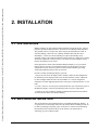
2.3. MARQUEE DISPLAY MOUNTING HOLE
The Marquee Display system was designed to be mounted in several configurations.
There is a standard mounting hole in each end wall of the Marquee display. Each end
wall is reinforced with a 4 inch square 12-gauge steel plate with a welded nut to
accept a 3/8 - 16 inch bolt.
3/8" - 16
THREADED
MOUNTING
HOLE
3 15/16"
2 13/16
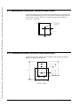
2.4. HANGING/WALL MOUNTING BRACKET
This bracket is an option which will allow hanging or wall mounting the Marquee
Display. The bracket is shown below.
8
7
10 1/4
4 1/4
1 1/2
2
5 5/8
SM1000HWB
8
QUICKMARQUEE DISPLAY
Courtesy of Steven Engineering, Inc. Ÿ 230 Ryan Way, South San Francisco, CA, 94080-6370 Ÿ Main Office: (650) 588-9200 Ÿ Outside Local Area: (800) 258-9200 Ÿ www.stevenengineering.com
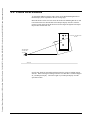
2.5. CHAIN SUSPENSION
To suspend the Marquee Display from a chain, use the Wall Mounting Bracket so
that the display can be adjusted for the best viewing angle.
Mount the bracket so that the hole nearest the bend in the Mounting Bracket is used
to attach the bolt to the threaded hole in the Marquee display end wall. Select the
required viewing angle and tilt the bracket to desired angle and tighten bolt. Repeat
the procedure for the other side.
CHAIN MOUNTING
HOLE
PROBABLE
VIEWING
POINT
FLOOR
Now the unit should be suspended with chains from the ceiling or building support
structure. When selecting a mounting location be sure that there is sufficient support
for your Marquee Display. Check the weight of your Marquee Display from the
specification table.
QUICKMARQUEE DISPLAY
9
Courtesy of Steven Engineering, Inc. Ÿ 230 Ryan Way, South San Francisco, CA, 94080-6370 Ÿ Main Office: (650) 588-9200 Ÿ Outside Local Area: (800) 258-9200 Ÿ www.stevenengineering.com
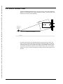
2.6. WALL MOUNTING
Each SM1000HWB Mounting Bracket can also be used to wall mount the Marquee
Display. Use the middle hole to support the Marquee Display. The bent angle on the
bracket has two holes for wall mounting.
WALL
TYPICAL
VIEWING
POINT
TYPICAL DISTANCE
FLOOR
First fasten the brackets to the Marquee Display, then locate the unit on the wall
where it will be mounted and mark the holes that need drilling. Make sure that the
mounting anchors you use can support the weight of your Marquee Display. Check
the weight of the Marquee display in the specification tables. Once your mounting
anchors are in place, reposition the Marquee Display and finish fastening the unit to
the wall.
10
QUICKMARQUEE DISPLAY
Courtesy of Steven Engineering, Inc. Ÿ 230 Ryan Way, South San Francisco, CA, 94080-6370 Ÿ Main Office: (650) 588-9200 Ÿ Outside Local Area: (800) 258-9200 Ÿ www.stevenengineering.com
2.7. BACK TO BACK MOUNTING BRACKET
This bracket is an option which will allow hanging a pair of Marquee Displays from a
single set of chains at a single location. The bracket is shown below.
1
8
10 7/6
1 1/2
1 1/2
1 1/2
6 11/32
12 11/16
17 1/4
SM1000BBB
For back to back installations match up the hole in one end of the bracket with the
hole in the center of the Marquee Display end wall. Select the required viewing angle
and tighten the bolt. Repeat the procedure for the other side of the first Marquee.
Now repeat the entire procedure for the second Marquee Display. Remember the
viewing angle for each side may be different, however, typically they will be the
same.
TYPICAL
DISTANCE
THIS SIDE
TYPICAL
DISTANCE
THIS SIDE
FLOOR
Now the unit should be suspended with chains from the ceiling or building support
structure. When selecting a mounting location be sure that there is sufficient support
for your back to back Marquee Display. Check the weight of your Marquee Display
from the specification table and multiply by 2.
QUICKMARQUEE DISPLAY
11
Courtesy of Steven Engineering, Inc. Ÿ 230 Ryan Way, South San Francisco, CA, 94080-6370 Ÿ Main Office: (650) 588-9200 Ÿ Outside Local Area: (800) 258-9200 Ÿ www.stevenengineering.com
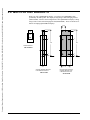
2.8. MULTIPLE UNIT BRACKETS
When you order a QM4204ROA Display, you will get two QM2204ROA units
permanently stacked together. The display is hung using a stacked hanging bracket
(SM1001SHB). A back-to-back configuration of two QM4204ROA Displays is hung
using a back-to-back stacked hanging bracket(SM1001BSB). These two brackets are
ONLY for hanging QM4204ROA Displays.
4.075
22.4
22.4
1
1
23.9
23.9
SINGLE BRACKET
SM1000HWB
1.
1.
0
2.50
STACKED HANGING BRACKET
FOR SM4204FOA DISPLAY
SM1001SHB
12
0
8.1
BACK-TO-BACK STACKED
HANGING BRACKET FOR
2 SM4204FOA DISPLAYS
SM1001BSB
QUICKMARQUEE DISPLAY
Courtesy of Steven Engineering, Inc. Ÿ 230 Ryan Way, South San Francisco, CA, 94080-6370 Ÿ Main Office: (650) 588-9200 Ÿ Outside Local Area: (800) 258-9200 Ÿ www.stevenengineering.com
2.9. ADJUSTABLE GLARE VISOR
The adjustable glare visor allows the user to compensate for ambient light conditions.
The darker the area in which the Marquee Display is mounted the greater the
visibility. Keep in mind that direct sunlight or factory lighting that is at the same
height as the Marquee Display will ``wash out'' the display and cause poor visibility.
LOOSEN NUT AND ADJUST
FROM 1 3/4" TO 2 1/2"
QUICKMARQUEE DISPLAY
13
Courtesy of Steven Engineering, Inc. Ÿ 230 Ryan Way, South San Francisco, CA, 94080-6370 Ÿ Main Office: (650) 588-9200 Ÿ Outside Local Area: (800) 258-9200 Ÿ www.stevenengineering.com
2.10. POWER CABLE/COMMUNICATIONS CABLE
ACCESS PLATE
The power cable/communications cable access plate cover should be removed and
then punched to accept raceway fittings that will terminate your cable runs. If your
local plant/electrical codes allow, this fitting will terminate a flexible whip from your
rigid power/communications wire runs.
The power cable must be installed according to local codes. Make sure your power
source can support the total electrical load connected to it. Provide proper circuit
protection and mechanical raceways. To make installation easier, plan on using a
flexible raceway for the last three feet or longer if allowed by code. Also, leave at
least three feet of wire pulled past the final fitting to allow dressing when connecting
to the Marquee display terminal.
To gain access to the connection terminals, there are two cover plates (a large one
and a small one) on the top of the Marquee Display.
Power Cable/ Communications Cable
Access Plate
14
Terminal Cover Plate
QUICKMARQUEE DISPLAY
Courtesy of Steven Engineering, Inc. Ÿ 230 Ryan Way, South San Francisco, CA, 94080-6370 Ÿ Main Office: (650) 588-9200 Ÿ Outside Local Area: (800) 258-9200 Ÿ www.stevenengineering.com
3. ELECTRICAL
3.1. GROUNDING
IMPORTANT!
When connecting a host device to one or more Marquee Displays it is very important
to have each device connected to a common ground and common power supply.
Good grounding cannot be over stressed. A complex system must have only one
ground point for common power supplies and signal returns to prevent ground loops.
We recommend Belden 9463 wire or other quality 22 gauge twisted shielded pair
wire and connecting the shields to common ground at both ends of the wire.
Proper grounding of the Display System will prevent symptoms that appear as
malfunctions during normal "RUN" operation.
3.2. WIRE RUNS AND WIRING
DO NOT route control or data wires with power or high voltage wires other than
Marquee power. Always use twisted shielded pair wire or Belden 9463 which
provides a very effective shield against electrostatic and magnetic coupling.
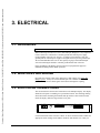
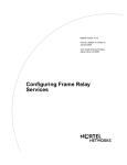
3.3. ELECTRICAL CONNECTIONS
This section describes the electrical connections to the Marquee Display. The display
should be tested prior to installing it in a permanent location. The following drawing
shows the bracket containing the terminals and dip switches. This bracket if found
inside the display, under the large terminal cover plate.
L
G
N
1 2 3 456 7
1 2
A
B
FUSE
Use the information in this section to connect AC Power and host interface. Make the
appropriate switch settings for the address, baud rate and character size. Once you
QUICKMARQUEE DISPLAY
15
Courtesy of Steven Engineering, Inc. Ÿ 230 Ryan Way, South San Francisco, CA, 94080-6370 Ÿ Main Office: (650) 588-9200 Ÿ Outside Local Area: (800) 258-9200 Ÿ www.stevenengineering.com
are sure all connections and settings are correct, turn on the power and watch the unit
go through the self test cycle. When the self test has completed, the display will go
blank and wait for commands from the host device.
3.4. CONNECTING AC POWER (TERMINALS L, G, N)
Connect the 115VAC hot lead to Terminal L. The neutral lead should be connected
to Terminal N. Terminal G earth ground must be connected to a reliable low
impedance path to protect the display from electrical noise. This ground connection
will also protect personnel from electrical shock in case of equipment failure. The
terminal strip is shown below.
POWER CONNECTION
L
G
N
1 2 3 456 7
A
1 2
B
FUSE
Dress wires to the proper length and connect to a 115VAC +/- 10%, 47 to 63 Hz
voltage source. The 115VAC supply line to the Marquee Display should have a 15
amp branch short circuit protection maximum.
3.5. SERIAL COMMUNICATION (TERMINALS 1-7)
The location of the serial communication connector is shown below. This connector
is a pluggable 7 position terminal block which may be removed to facilitate wire
connections.
SERIAL COMMUNICATION
CONNECTOR
L
G
N
1 2 3 456 7
A
1 2
B
FUSE
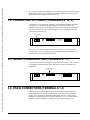
3.6. RS232 CONNECTIONS (TERMINALS 1-3)
RS232 is the most common interface specification among controllers supporting
serial communication. This specification allows connection of only one Marquee
display, with a maximum recommended cable length of 50 feet. Consider using
RS422/485 for applications that exceed these limitations. If you are connecting the
Marquee Display to a Marquee Controller, the RS422 protocol will be used.
16
QUICKMARQUEE DISPLAY
Courtesy of Steven Engineering, Inc. Ÿ 230 Ryan Way, South San Francisco, CA, 94080-6370 Ÿ Main Office: (650) 588-9200 Ÿ Outside Local Area: (800) 258-9200 Ÿ www.stevenengineering.com
SERIAL COMMUNICATION
CONNECTOR
1 2 3 456 7
GROUND
RS232 IN
RS232 OUT
The Marquee Display's RS232 port does not support any hardware or software
handshaking functions. Only the RS232 IN (Receive) terminal is used, along with the
ground terminal.
The following shows a typical connection between a host device RS232 port and the
Marquee display.
TYPICAL HOST DEVICE
MARQUEE DISPLAY
Pin Designations
TERMINALS
RS232
SHIELD
1
RS232 IN
2
Transmit
2
Receive (not used)
3
Signal Common
7
1
RS232 OUT
3
GROUND
NOTE: Some devices require that certain hardware handshaking lines be asserted
Refer to applicable product literature.
It is generally recommended that the shield be connected at the display end only, as
shown in the diagram above.
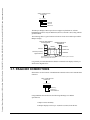
3.7. RS422/485 CONNECTIONS
Shown below are the location of the RS422 IN terminals on the serial communication
connector.
SERIAL COMMUNICATION
CONNECTOR
1 2 3 456 7
RS422 IN (-)
RS422 IN (+)
GROUND/SHIELD
Using an RS422/485 interface has the following advantages over RS232
specifications:
1. Improved noise immunity.
2. Marquee displays can be up to 10,000 feet (2 miles) from the host
QUICKMARQUEE DISPLAY
17
Courtesy of Steven Engineering, Inc. Ÿ 230 Ryan Way, South San Francisco, CA, 94080-6370 Ÿ Main Office: (650) 588-9200 Ÿ Outside Local Area: (800) 258-9200 Ÿ www.stevenengineering.com
controller.
3. Up to 32 Marquee Displays can be connected directly to a host
controller's RS422/485 port. 123 Marquee Displays can be
addressed when line repeaters are used.
The Marquee Display's RS422/485 input port does not support any hardware or
software handshaking functions.
The following diagram shows a typical RS422/485 connection to a Marquee display.
This example shows the connection to the Marquee Controller (SM1000SMC).
TYPICAL HOST
Pin Designations
RS422
MARQUEE
DISPLAY
Additional Marquee Displays
can be multidropped
as shown
3
3
SMC+
11
6
6
SMC-
10
7
7
RS422 (+)
RS422 (-)
NOTE: Some devices require than certain hardware handshaking lines be asserted.
Refer to applicable host device product literature.
The shield should be connected at one end only (either end is ok), as shown in the
above diagram.
NOTE: The RS422 OUT port is not active and no connections should be made to this
port.
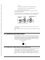
3.8. OPEN COLLECTOR OUTPUT
The Marquee Display is capable of controlling an open collector circuit that can
drive a relay with up to 150 ma. at 24 VDC. A two position pluggable terminal strip
is used to facilitate the connection. The relay should be connected to the terminal
strip at terminal 1. A ground connection is provided at terminal 2 to establish a
common ground with the power supply driving the relay.
OPEN COLLECTOR OUTPUT
CONNECTOR
1 2
GROUND
D OUT
3.9. DISPLAY CONFIGURATION (Switch A)
On power up, the Marquee Display will perform a number of functions in order to
properly configure itself. The Marquee starts by displaying "AUTO
CONFIGURING", at which point it is determining the number of displays that make
up the complete sign. For example, a QM4204ROA is made up of 4 individual
displays or lines. Further configuration is done through DIP switches labeled A and
B:
18
QUICKMARQUEE DISPLAY
Courtesy of Steven Engineering, Inc. Ÿ 230 Ryan Way, South San Francisco, CA, 94080-6370 Ÿ Main Office: (650) 588-9200 Ÿ Outside Local Area: (800) 258-9200 Ÿ www.stevenengineering.com
A
ON
87654321
B
87654321
The Marquee reads each bank of switches and configures its baud rate, character size,
protocol and address accordingly. Below is the label that defines the settings for
Switch A.
SWITCH 'A' CODES
BAUD RATE
2
1
CHAR. SIZE
4
3
300
OFF
OFF
2.1 ONLY
OFF
OFF
1200
OFF
ON
4.8 ONLY
OFF
ON
9600
ON
ON
2.1 & 4.8
ON
ON
19200
ON
OFF
4.8 SMC MODE
ON
OFF
PROTOCOL
6
5
SELF TEST
8
7
RSVD 1
OFF
OFF
TEST 1
OFF
OFF
RSVD 2
OFF
ON
TEST 2
OFF
ON
SLAVE
ON
ON
DISABLED
ON
ON
RSVD 3
ON
OFF
TEST 3
ON
OFF
Note: All switches set to the ON position is the default setting as set by the factory.
This is the most common configuration. The user is advised not to change the
settings unless specifically required by the application.
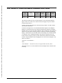
3.10.BAUD RATE SELECTION (Switch A)
On power up, the Marquee display will read the baud rate selected by switch bank A,
switches 1 & 2 and display the selected baud rate during the power up display cycle.
The baud rate is selectable for 300, 1200, 9600 and 19200 Baud, as shown on the
display label. The Baud rate is selected by changing switches 1 and 2 of switch bank
A. The Baud rate table is shown below.
QUICKMARQUEE DISPLAY
BAUD RATE
2
1
300
OFF
OFF
1200
OFF
ON
9600
ON
ON
19200
ON
OFF
19
Courtesy of Steven Engineering, Inc. Ÿ 230 Ryan Way, South San Francisco, CA, 94080-6370 Ÿ Main Office: (650) 588-9200 Ÿ Outside Local Area: (800) 258-9200 Ÿ www.stevenengineering.com
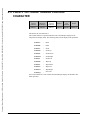
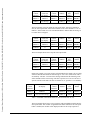
3.11.CHARACTER SIZE SELECTION (Switch A)
Four different character size settings exist for the Marquee. Unless you are using a
multilined Marquee such as a QM4204ROA, the default setting (2.1" and 4.8"
characters) should be selected. The character size settings are shown below.
CHAR. SIZE
4
3
2.1 ONLY
OFF
OFF
4.8 ONLY
OFF
ON
2.1 & 4.8
ON
ON
4.8 SMC MODE
ON
OFF
Why different character size settings? Their are two reasons for providing this
feature. First, depending on the character size requirements of the application, the
2.1" ONLY and 4.8" ONLY settings may simplify the programming in the host
device. Second, the different character size settings allow specific models of marquee
displays to be compatible with specific devices. For example, when slaving a
QM4204ROA marquee from a 4 line SMART SIM/MC or ALLEN BRADLEY
DL20/DL40, it is necessary for the 4.8" ONLY character size setting to be selected.
Each character size setting affects the way the line number field in the slave protocol
is interpreted. Below is a table containing these differences. See also the
communications section of this manual.
FIELD 5
LINE #
2.1" ONLY
4.8" ONLY
4.8" SMC
Mode
2.1" & 4.8"
Line 1
Line 1
Line 1
Line 1 - 2"
Control B
Line 2
Line 2
Line 2
Line 2 - 2"
Control C
Line 3
Line 3
-
Line 1 - 4.5"
Control D
Line 4
Line 4
Line 3
Line 3 - 2"
Control E
Line 5
Line 5
Line 4
Line 4 - 2"
Control G
Line 6
Line 6
-
Line 2 - 4.5"
Control H
Line 7
Line 7
-
Line 5 - 2"
Control I
Line 8
Line 8
-
Line 6 - 2"
Control K
-
-
-
Line 3 - 4.5"
Control L
-
-
-
Line 7 - 2"
Control N
-
-
-
Line 8 - 2"
Control O
-
-
-
Line 4 - 4.5"
Control A
When using the Marquee Controller, only use either 2.1" & 4.8" or 4.8" SMC
MODE. This will insure compatibility with the Marquee Controller. Note: The 4.8"
SMC MODE is the equivalent of LARGE MODE on the SMART Marquee displays.
20
QUICKMARQUEE DISPLAY
Courtesy of Steven Engineering, Inc. Ÿ 230 Ryan Way, South San Francisco, CA, 94080-6370 Ÿ Main Office: (650) 588-9200 Ÿ Outside Local Area: (800) 258-9200 Ÿ www.stevenengineering.com
Refer to the applications section of this manual for further discussion on specific
applications requiring the 2.1" ONLY and 4.8" ONLY character modes.
3.12.PROTOCOL SELECTION (Switch A)
Switches 5 and 6 control the protocol setting. The SLAVE protocol is the only
protocol currently available. The remaining settings are reserved for future use.
Below is the table for setting the protocol.
PROTOCOL
6
5
RSVD 1
OFF
OFF
RSVD 2
OFF
ON
SLAVE
ON
ON
RSVD 3
ON
OFF
3.13.SELF TEST SELECTION (Switch A)
Switches 7 and 8 control the self test setting. These switches must both be set to on
in order for the SLAVE protocol to operate normally. The table below shows the
self test settings. These tests are used by factory technicians to diagnose problems
with the display. Contact the factory for assistance using this feature.
SELF TEST
8
7
TEST 1
OFF
OFF
TEST 2
OFF
ON
DISABLED
ON
ON
TEST 3
ON
OFF
TEST 1: Controller board production test.
TEST 2: Display burn-in test.
1. Test Blocks
2. Display Internal Temperature
3. Output On
4. Output Off
5. RS422 loopback.
6. RS232 loopback
7. Alpha port test
8. Failure report
TEST 3: Trouble shooting test determined by switch bank B.
1. Switch B = 1: Display character received on RS422 port.
2. Switch B = 2: Send characters out RS422 port.
3. Switch B = 3: Display AtoD number.
4. Switch B = 4: Turn output on.
5. Switch B = 5: Toggle output every 5 seconds.
QUICKMARQUEE DISPLAY
21
Courtesy of Steven Engineering, Inc. Ÿ 230 Ryan Way, South San Francisco, CA, 94080-6370 Ÿ Main Office: (650) 588-9200 Ÿ Outside Local Area: (800) 258-9200 Ÿ www.stevenengineering.com
6.
7.
8.
9.
10.
Switch B = 6: Run dipswitch test.
Switch B = 7: RS232 loopback.
Switch B = 8: RS422 loopback.
Switch B = 9: Alpha port test.
Switch B = 10: Watchdog test.
3.14.ADDRESS SELECTION (Switch B)
Upon power up, the Marquee Display will read the address selected by switch B and
display that address during the power up display cycle.
The Marquee display address can be set from 1 to 127. Note that addresses: 0, 6, 10,
13, and 18 are reserved and would be interpreted as address 127:
Marquee display address 127 is a special slave address that will display all slave
messages regardless of their address. Marquee display addresses need not be unique,
a Marquee Display network may have two or more units with the same address as in
the case of back to back units that display the same message on both sides.
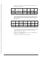
The display label showing the address select table is shown below. Starting at address
1, the switch settings are selected using a binary format, with switch 7 being the most
significant digit. Switch 8 is not currently used.
SWITCH 'B' CODES
ADDRESS
8
7
6
5
4
3
2
1
127
OFF
OFF
OFF
OFF
OFF
OFF
OFF
OFF
1
OFF
OFF
OFF
OFF
OFF
OFF
OFF
ON
2
OFF
OFF
OFF
OFF
OFF
OFF
ON
OFF
-
OFF
-
-
-
-
-
-
-
-
OFF
-
-
-
-
-
-
-
126
OFF
ON
ON
ON
ON
ON
ON
OFF
127
OFF
ON
ON
ON
ON
ON
ON
ON
ILLEGAL ADDRESSES 6, 10, 13, 18 & O
WILL DEFAULT TO 127 IF PROGRAMMED
3.15.FINAL CHECKS
After all the connections are made, including power and communications, the power
should be applied and the unit tested for proper operation. If you change any switch
setting, the power must be cycled in order for the new setting to be read.
Once proper operation has been established, the display is ready to install in a
permanent location. See Section 2 for mechanical installation details.
The terminal cover plate should be securely fastened to the top of the Marquee
Display to re-establish its NEMA 12/4 rating.
When the display is mounted in a permanent location, turn on the power and view the
display. As part of the Marquee Display start-up, it will light up all display segments
22
QUICKMARQUEE DISPLAY
Courtesy of Steven Engineering, Inc. Ÿ 230 Ryan Way, South San Francisco, CA, 94080-6370 Ÿ Main Office: (650) 588-9200 Ÿ Outside Local Area: (800) 258-9200 Ÿ www.stevenengineering.com
and execute a self test. The display will show which switch setting are selected. It
will then go blank and wait for commands from the host device.
A sample self test is shown below.
AUTO CONFIGURING
2LINEX20CHARX2.1INCH
2.1" & 4.8" CHARS.
SLAVE
VERSION 1.0
9600 BAUD
ADDRESS 127
This page intentionally left blank.
QUICKMARQUEE DISPLAY
23
24
QUICKMARQUEE DISPLAY
Courtesy of Steven Engineering, Inc. Ÿ 230 Ryan Way, South San Francisco, CA, 94080-6370 Ÿ Main Office: (650) 588-9200 Ÿ Outside Local Area: (800) 258-9200 Ÿ www.stevenengineering.com
Courtesy of Steven Engineering, Inc. Ÿ 230 Ryan Way, South San Francisco, CA, 94080-6370 Ÿ Main Office: (650) 588-9200 Ÿ Outside Local Area: (800) 258-9200 Ÿ www.stevenengineering.com
4. COMMUNICATION
4.1. INTRODUCTION
This section of the manual covers the slave protocol. The information in this section
is presented using conventions that are defined as follows.
QUICKMARQUEE DISPLAY
1.
The “/” character is used to separate the fields of the protocol for the purpose of
presenting the information and is not actually part of the protocol.
2.
Words contained within the “<“ and “>“ symbols are not part of the protocol but
references to the actual information to be substituted in place of the word and the
symbols. For example, in place of <text>, one would put the actual message to
be displayed.
3.
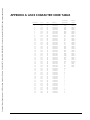
The ASCII code for Control (CTRL) characters, Carriage Return and the
ESCAPE character can be found in the Appendix section of this manual.
Wherever ESCAPE or Control is used in the protocol, the equivalent ASCII
code should be used. Do not use the characters that make up the word ESCAPE
or Control.
4.
Whenever applicable, the decimal representation of the ASCII code is provided
in parenthesis. For example: A (65). The Appendix section of this manual
contains a complete ASCII code table.
25
Courtesy of Steven Engineering, Inc. Ÿ 230 Ryan Way, South San Francisco, CA, 94080-6370 Ÿ Main Office: (650) 588-9200 Ÿ Outside Local Area: (800) 258-9200 Ÿ www.stevenengineering.com
4.2. SLAVE PROTOCOL FORMAT
All the information that creates a message must be formatted and sent by the host
computer or programmable logic controller. Restrictions for the various fields are
listed in each section. Samples are shown at the end of this chapter. The information
packet that the host will transmit consists of the following packet:
Optional
Control
Character
250
Characters
for Display
Optional
Control
Character
Device
Address
Display
Line
Number
Carriage
Return
FIELD 1
FIELD 2
FIELD 3
FIELD 4
FIELD 5
FIELD 6
Field 1 - optional control character header that establishes a functional command.
Not used with Field 3.
Field 2 - can consist of any printable ASCII character
Field 3 - optional control character trailer that establishes a display mode.
Not used with Field 1.
Field 4 - routes the message packet to the proper Marquee Display(s).
Field 5 - tells the Marquee Display on which line to display the message.
Field 6 - signifies the end of a data packet.
26
QUICKMARQUEE DISPLAY
Courtesy of Steven Engineering, Inc. Ÿ 230 Ryan Way, South San Francisco, CA, 94080-6370 Ÿ Main Office: (650) 588-9200 Ÿ Outside Local Area: (800) 258-9200 Ÿ www.stevenengineering.com
4.3. FIELD 1 - HEADER CONTROL CHARACTERS FOR
AUTO REPEAT
Optional
Control
Character
250
Characters
for Display
Optional
Control
Character
Device
Address
Display
Line
Number
Carriage
Return
FIELD 1
FIELD 2
FIELD 3
FIELD 4
FIELD 5
FIELD 6
This field is not used with field 3.
The following AUTO REPEAT MODE allows messages to be downloaded into the
Marquee and then left to run continuously. There is room for approximately 5000
bytes of message storage.
Control S - This command followed by a slave address, a don't care byte and a CR,
will clear out the auto repeat buffer and if it is in the auto repeat mode, it will stop. It
is a good idea to always start out with this command before downloading a new
sequence of messages.
/CTRL S / <slave address> / <don't care> / carriage return
* Don't care bytes cannot be a CR, CTRL R, or CTRL F. We suggest sending the
address again.
Control Y - This command will tell the slave marquee to add the following text field
and mode control information to it's auto repeat memory. This string can be no longer
than 255 bytes and also must be terminated with a slave number, a don't care byte,
and a CR. (This is part of the 255 byte limitation.) A particular message can also be
added to the buffer without breaking up the display flow, this is particularly useful
for long scroll mode messages. The format is:
/CTRL Y / <text field> / <slave address> / <don't care> / carriage return
Control W - This command will enable the AUTO REPEAT mode. There are three
modifiers that are associated with this command:
ASCII
0
DECIMAL
48
1
49
2
50
DEFINITION
Resume where stopped, even if its in the
middle of a message. The message must be a
line type message, not a roll or smooth scroll.
Resume at the beginning of a message run
previous to stopping.
Start at the beginning of the buffer.
No modifier with this command is the same as using a 2 modifier. Again the message
must contain an address, don't care byte, and a carriage return. The format is:
/ CTRL W / <modifier> / <slave address> / <don't care> / carriage return
This command can be used in conjunction with the stop command that is discussed
next.
Control X - This command will stop the auto repeat mode without destroying the
buffer's content, which will allow the unit to start up using CTRL W. This command
is useful when an alarm message is to be posted. The auto repeat can be stopped and
QUICKMARQUEE DISPLAY
27
Courtesy of Steven Engineering, Inc. Ÿ 230 Ryan Way, South San Francisco, CA, 94080-6370 Ÿ Main Office: (650) 588-9200 Ÿ Outside Local Area: (800) 258-9200 Ÿ www.stevenengineering.com
a regular message can be sent via the standard protocol. Then the auto repeat mode
can be restarted. The format is:
/ CTRL X / <slave address> / <don't care> / carriage return
4.3.1. AUTO REPEAT - TEXT FIELD FORMAT
/CTRL Y / <text field> / <slave address> / <don't care> / carriage return
The text field that is sent to the display has it's own format to allow the display mode,
line number and wait times to be changed throughout the message program. If the
user simply sends text without any mode control codes, the display will default to line
mode, line 1 and wait time of one second. To change the modes the following
sequence must be sent before the text string in the text field;
1. An ESC (Escape) code and a ASCII T will tell the slave that the following data is
meant to be a text string with attributes.
2. The line number will tell the slave what line the text is to be displayed on.
Line number is an ASCII character in the range of "0" (49) to "<" (60) and "O" (79).
28
ASCII
Decimal
2.1"
ONLY
4.8"
ONLY
4.8" SMC
Mode
2.1" & 4.8"
0
48
All Line
All Line
All Line
All Line - 2.1"
1
49
Line 1
Line 1
Line 1
Line 1 - 2.1"
2
50
Line 2
Line 2
Line 2
Line 2 - 2.1"
3
51
Line 3
Line 3
-
Line 1 - 4.8"
4
52
Line 4
Line 4
Line 3
Line 3 - 2.1"
5
53
Line 5
Line 5
Line 4
Line 4 - 2.1"
6
54
Line 6
Line 6
-
Line 2 - 4.8"
7
55
Line 7
Line 7
-
Line 5 - 2.1"
8
56
Line 8
Line 8
-
Line 6 - 2.1"
9
57
-
-
-
Line 3 - 4.8"
:
58
-
-
-
Line 7 - 2.1"
;
59
-
-
-
Line 8 - 2.1"
<
60
-
-
-
Line 4 - 4.8"
O
79
All lines
All Lines
All Lines
All Line - 4.8"
QUICKMARQUEE DISPLAY
Courtesy of Steven Engineering, Inc. Ÿ 230 Ryan Way, South San Francisco, CA, 94080-6370 Ÿ Main Office: (650) 588-9200 Ÿ Outside Local Area: (800) 258-9200 Ÿ www.stevenengineering.com
3. Display mode will tell how the text will be displayed.
Display mode is a ASCII value in the range of 0 (48) to 9 (57) and A (65) to C (67).
ASCII
Decimal
Display Mode
0
48
line mode
1
49
line mode
2
50
flash mode
3
51
smooth scroll mode
4
52
scroll up mode
5
53
scroll down mode
6
54
scroll right mode
7
55
scroll left mode
8
56
wipe up mode
9
57
wipe down mode
A
65
wipe left mode
B
66
wipe right mode
C
67
roll up mode
4. Wait time will tell the slave how long, in seconds, it should wait before starting
the next message or the time between updating the display for multiple display
messages.
Wait time is a ASCII two digit number that gives the delay time between updates of a
line in a single line mode or all lines in all line mode. It can range from 0 (48) / 0
(48), to 9 (57) / 9 (57) seconds.
The format of the text field data is:
ESCAPE / T / line number / display mode / two byte wait time / text...../
The text is any printable ASCII character or variable field. The color switch is also
allowed for use with the tricolor displays. In line mode, the lines of text will
automatically be broken up and centered. Remember, this is the format for the text
field, and is included as part of the whole message string.
QUICKMARQUEE DISPLAY
29
Courtesy of Steven Engineering, Inc. Ÿ 230 Ryan Way, South San Francisco, CA, 94080-6370 Ÿ Main Office: (650) 588-9200 Ÿ Outside Local Area: (800) 258-9200 Ÿ www.stevenengineering.com
4.3.2. AUTO REPEAT - TEXT FIELD VARIABLE
The text field may also have an escape sequence embedded in it to signal that a
variable is to be inserted there. The sequence is a ESCAPE (27) to tell the slave there
is a field coming up, a V (86) to tell the slave a variable number is to follow, and an
ASCII number from 0 (48) to 9 (57), which is the actual variable number that will be
inserted at this point in the message program. The format is:
/ ESCAPE/ V / <ASCII digit 0 to 9> /
Where 0 to 9 is the variable number. The slave marquee variable can be a string of 32
displayable ASCII characters. There can be up to ten variables. If the message is
being displayed that is to have a variable embedded but no variable exists, then
nothing will appear in its place. The slave can be loaded with these variables
independent of the auto repeat mode. To send over a variable, the sequence is as
follows:
/CTRL V / <variable number (ASCII 0 to 9)> / <Text (up to 32 characters)>/
<address> / <don't care> / carriage return /
The variable feature allows users to send over messages that should remain constant
but embedded with a message(s) that can change, i.e., time of day, temperature, parts
count, etc.
30
QUICKMARQUEE DISPLAY
Courtesy of Steven Engineering, Inc. Ÿ 230 Ryan Way, South San Francisco, CA, 94080-6370 Ÿ Main Office: (650) 588-9200 Ÿ Outside Local Area: (800) 258-9200 Ÿ www.stevenengineering.com
4.4. FIELD 2 - DISPLAYABLE CHARACTER FIELD
Optional
Control
Character
250
Characters
for Display
Optional
Control
Character
Device
Address
Display
Line
Number
Carriage
Return
FIELD 1
FIELD 2
FIELD 3
FIELD 4
FIELD 5
FIELD 6
This field can contain up to 250 viewable characters. Any valid ASCII character,
upper or lower case, can be sent. Control codes do not apply except for Control F
Control R and Control U.
Control F will cause the characters of the entire string to flash. A second Control F
will cancel the flash mode.
Control R is interpreted as a reset command and all data registers in the Marquee
Display are cleared and you will be required to transmit new characters for display.
In other words, if you were to send 10 characters, then a Control R, your previous 10
characters are lost and any following characters would be accepted by the Marquee
Display. Control R also resets the flash status to not flashing. It is recommended that
a Control R be sent to all Marquee displays when the host controller powers up,
because when a serial port powers up it may inadvertently transmit erroneous data.
Control U has been added to allow changing the text color for tricolor displays. The
format is as follows:
/Control U/ <color character>/
where,
<color character > = R (82) for red, G (71) for green and Y (89) for yellow.
The default color is red. This command can be used multiple times within the same
text string.
QUICKMARQUEE DISPLAY
31
Courtesy of Steven Engineering, Inc. Ÿ 230 Ryan Way, South San Francisco, CA, 94080-6370 Ÿ Main Office: (650) 588-9200 Ÿ Outside Local Area: (800) 258-9200 Ÿ www.stevenengineering.com
4.5. FIELD 3 - OPTIONAL TRAILER CONTROL
CHARACTER
Optional
Control
Character
250
Characters
for Display
Optional
Control
Character
Device
Address
Display
Line
Number
Carriage
Return
FIELD 1
FIELD 2
FIELD 3
FIELD 4
FIELD 5
FIELD 6
This field is not used with field 1.
This control character is optional and when sent to the Marquee display will be
interpreted as a display mode. The following table lists the display mode operations.
Control A
-
Hold
Control B
-
Flash
Control C
-
Scroll
Control D
-
Scroll Up
Control E
-
Scroll Down
Control H
-
Scroll Right
Control I
-
Scroll Left
Control K
-
Wipe Up
Control L
-
Wipe Down
Control N
-
Wipe Left
Control O
-
Wipe Right
Control Q
-
Not Used
If no control character is sent in field 3 then the Marquee display will default to line
mode operation.
32
QUICKMARQUEE DISPLAY
Courtesy of Steven Engineering, Inc. Ÿ 230 Ryan Way, South San Francisco, CA, 94080-6370 Ÿ Main Office: (650) 588-9200 Ÿ Outside Local Area: (800) 258-9200 Ÿ www.stevenengineering.com
4.6. FIELD 4 - DEVICE ADDRESS
Optional
Control
Character
250
Characters
for Display
Optional
Control
Character
Device
Address
Display
Line
Number
Carriage
Return
FIELD 1
FIELD 2
FIELD 3
FIELD 4
FIELD 5
FIELD 6
This is a one byte ASCII character ranging anywhere from 1 through 127 decimal (1
through 7F Hex). It should be noted that addresses 0, 6, 10, 13, and 18 are illegal
addresses. Any Marquee display addressed as 127 will understand any data that is
transmitted regardless of what the address is in the packet. In addition, any packet
containing the address 127 is understood by all Marquee displays regardless of their
addresses. This allows you to efficiently route a message to all displays. Multiple
Marquee displays on an RS422/485 communication line can have the same address
and they will all respond to a message sent to that address.
Remember, this field must be a ASCII character, not a decimal number. For
example:
DEVICE ADDRESS
(DECIMAL)
1
2
11
48
68
102
QUICKMARQUEE DISPLAY
ASCII CHARACTER
CTRL-A
CTRL-B
CTRL-K
0 (ZERO)
D (Upper Case D)
f (Lower Case f)
33
Courtesy of Steven Engineering, Inc. Ÿ 230 Ryan Way, South San Francisco, CA, 94080-6370 Ÿ Main Office: (650) 588-9200 Ÿ Outside Local Area: (800) 258-9200 Ÿ www.stevenengineering.com
4.7. FIELD 5 - LINE NUMBER
Optional
Control
Character
250
Characters
for Display
Optional
Control
Character
Device
Address
Display
Line
Number
Carriage
Return
FIELD 1
FIELD 2
FIELD 3
FIELD 4
FIELD 5
FIELD 6
This is a one byte ASCII character defined as 1, 2, 3, 4, 5, 7, 8, 9, 11, 12, 14, 15, 48,
49 or 50 decimal. The following table defines the line number results.
ASCII
Decimal
2.1"
ONLY
4.8"
ONLY
4.8" SMC
Mode
2.1" & 4.8"
Control A
1
Line 1
Line 1
Line 1
Line 1 - 2.1"
Control B
2
Line 2
Line 2
Line 2
Line 2 - 2.1"
Control C
3
Line 3
Line 3
-
Line 1 - 4.8"
Control D
4
Line 4
Line 4
Line 3
Line 3 - 2.1"
Control E
5
Line 5
Line 5
Line 4
Line 4 - 2.1"
Control G
7
Line 6
Line 6
-
Line 2 - 4.8"
Control H
8
Line 7
Line 7
-
Line 5 - 2.1"
Control I
9
Line 8
Line 8
-
Line 6 - 2.1"
Control K
11
-
-
-
Line 3 - 4.8"
Control L
12
-
-
-
Line 7 - 2.1"
Control N
14
-
-
-
Line 8 - 2.1"
Control O
15
-
-
-
Line 4 - 4.8"
0
48
RELAY ON
1
49
RELAY OFF
2
50
BLANK ALL LINES
Note that text contained in the text field will not be displayed when either 0 (48), 1
(49), or 2 (50) are used in the line number field.
34
QUICKMARQUEE DISPLAY
Courtesy of Steven Engineering, Inc. Ÿ 230 Ryan Way, South San Francisco, CA, 94080-6370 Ÿ Main Office: (650) 588-9200 Ÿ Outside Local Area: (800) 258-9200 Ÿ www.stevenengineering.com
4.8. FIELD 6 - CARRIAGE RETURN
Optional
Control
Character
250
Characters
for Display
Optional
Control
Character
Device
Address
Display
Line
Number
Carriage
Return
FIELD 1
FIELD 2
FIELD 3
FIELD 4
FIELD 5
FIELD 6
The carriage return defines an end of message and tells the Marquee Display to
execute it and defines a starting point so that the Marquee Display can interpret each
byte sent.
4.9. EXAMPLES
The following examples are intended for use with a Marquee Display set to the
default character mode of 2.1” & 4.8” characters.
4.9.1. STANDARD FORMAT MESSAGES
The following format used by a Marquee Display is the simplest format and uses
only four fields as shown below.
Optional
Control
Character
250
Characters
for Display
Optional
Control
Character
Device
Address
Display
Line
Number
Carriage
Return
FIELD 1
FIELD 2
FIELD 3
FIELD 4
FIELD 5
FIELD 6
CTRL-A
CTRL-A
CTRL-M
Message 1
In the above sample information packet, the device address is 1 (decimal) or ASCII
CTRL-A. The character line selected to display the message is line 1 (decimal) or
ASCII CTRL-A. The end of packet character is a CARRIAGE RETURN or ASCII
CTRL-M.
Another information packet may contain a single optional control character, such as a
control code to pulse the relay (CTRL-G). The format for this type of message is
shown below.
Optional
Control
Character
250
Characters
for Display
Optional
Control
Character
Device
Address
Display
Line
Number
Carriage
Return
FIELD 1
FIELD 2
FIELD 3
FIELD 4
FIELD 5
FIELD 6
CTRL-A
CTRL-A
CTRL-M
CTRL-G
QUICKMARQUEE DISPLAY
35
Courtesy of Steven Engineering, Inc. Ÿ 230 Ryan Way, South San Francisco, CA, 94080-6370 Ÿ Main Office: (650) 588-9200 Ÿ Outside Local Area: (800) 258-9200 Ÿ www.stevenengineering.com
In the above example, the four control characters are sent out and cause the relay to
pulse for .5 seconds. Control G (CTRL-G) is the command for pulsing the relay, the
device address is 1 (decimal) or CTRL-A, the display line number is 1 (decimal) or
CTRL-A, and finally the end of packet character, CTRL-M. Note that the display
line number has no meaning in this message, but is still required as part of the format.
Another information packet may contain a message and a control character that
defines the display mode, such as message flash or message scroll. The format is
shown below.
Optional
Control
Character
250
Characters
for Display
Optional
Control
Character
Device
Address
Display
Line
Number
Carriage
Return
FIELD 1
FIELD 2
FIELD 3
FIELD 4
FIELD 5
FIELD 6
Message
CTRL-C
CTRL-B
CTRL-A
CTRL-M
In the previous example, the message would scroll on line 1 of display # 2. CTRL-C
is the control character for scroll mode, the device address is 2 (decimal) or ASCII
CTRL-B, the display line number is 1 (decimal) or ASCII CTRL-A, and the end of
the packet character is CARRIAGE RETURN or CTRL-M.
In this example, the green color switch will be used. This information packet is
intended for a tricolor display.
250 Characters
for Display
Optional
Control
Character
Device
Address
Display
Line
Number
Carriage
Return
FIELD 2
FIELD 3
FIELD 4
FIELD 5
FIELD 6
CTRL-U G Green Message
CTRL-C
CTRL-B
CTRL-B
CTRL-M
4.9.2. AUTO REPEAT MESSAGES
In this example, the auto repeat buffer will be cleared.
Optional
Control
Character
250
Characters
for Display
Optional
Control
Character
Device
Address
Display
Line
Number
Carriage
Return
FIELD 1
FIELD 2
FIELD 3
FIELD 4
FIELD 5
FIELD 6
CTRL-A
CTRL-A
CTRL-M
CTRL-S
The next example shows how to load the auto repeat buffer with a text message. In
this example, the new message has no attributes sent with it, so the default settings
are line mode, line 1 and wait time of 1 second.
36
QUICKMARQUEE DISPLAY
Courtesy of Steven Engineering, Inc. Ÿ 230 Ryan Way, South San Francisco, CA, 94080-6370 Ÿ Main Office: (650) 588-9200 Ÿ Outside Local Area: (800) 258-9200 Ÿ www.stevenengineering.com
Optional
Control
Character
250
Characters
for Display
Optional
Control
Character
Device
Address
Display
Line
Number
Carriage
Return
FIELD 1
FIELD 2
FIELD 3
FIELD 4
FIELD 5
FIELD 6
CTRL-Y
New Message
CTRL-A
CTRL-A
CTRL-M
The next example is used to enable the auto repeat buffer. Once this command is
sent, the auto repeat buffer will start and continue to run. Note that there is a "0" in
FIELD 3, which in this case is the command modifier to indicate that the message is
to resume where it stopped.
Optional
Control
Character
250
Characters
for Display
Optional
Control
Character
Device
Address
Display
Line
Number
Carriage
Return
FIELD 1
FIELD 2
FIELD 3
FIELD 4
FIELD 5
FIELD 6
CTRL-W
0
CTRL-A
CTRL-A
CTRL-M
The next example shows how to stop the auto repeat buffer.
Optional
Control
Character
250
Characters
for Display
Optional
Control
Character
Device
Address
Display
Line
Number
Carriage
Return
FIELD 1
FIELD 2
FIELD 3
FIELD 4
FIELD 5
FIELD 6
CTRL-A
CTRL-A
CTRL-M
CTRL-X
In this next example, a new text message is downloaded to the display. The text field
will have attributes that define the new message as 4.8" text in scroll mode, with a 3
second delay. The ESC T in front of the message indicates that the following codes
will be attributes of the new message. The first 3 specifies 4.5" text size. The next 3
specifies smooth scroll mode. The last two characters, 03, specifies a 3 second delay.
Optional
Control
Character
250 Characters
for Display
Optional
Control
Character
Device
Address
Display
Line
Number
Carriage
Return
FIELD 1
FIELD 2
FIELD 3
FIELD 4
FIELD 5
FIELD 6
CTRL-Y
<ESC>T3303New Message
CTRL-A
CTRL-A
CTRL-M
<ESC> = ESCAPE or the ASCII Character with a decimal value of (27).
The next example shows how to enter a message with an embedded variable into the
auto repeat buffer. This variable is appended to the buffer. Whenever the auto repeat
buffer is enabled, the variable will be displayed wherever the escape sequence is
QUICKMARQUEE DISPLAY
37
Courtesy of Steven Engineering, Inc. Ÿ 230 Ryan Way, South San Francisco, CA, 94080-6370 Ÿ Main Office: (650) 588-9200 Ÿ Outside Local Area: (800) 258-9200 Ÿ www.stevenengineering.com
encountered. If the variable has no characters, nothing will be displayed when the
escape sequence is encountered.
Optional
Control
Character
250 Characters
for Display
Optional
Control
Character
Device
Address
Display
Line
Number
Carriage
Return
FIELD 1
FIELD 2
FIELD 3
FIELD 4
FIELD 5
FIELD 6
CTRL-Y
Temperature = <ESC>V1 C
CTRL-A
CTRL-A
CTRL-M
Once the variable is entered in the buffer, the variable can be updated anytime by
sending the following command. In this example, variable 1 is the text "400", and the
full message "Temperature = 400 C" will be displayed when the buffer encounters
escapes sequence 1.
Optional
Control
Character
Variable
ID#
(0-9)
FIELD 1
CTRL-V
1
250
Characters
for Display
Optional
Control
Character
Device
Address
Display
Line
Number
Carriage
Return
FIELD 2
FIELD 3
FIELD 4
FIELD 5
FIELD 6
CTRL-A
CTRL-A
CTRL-M
400
Variables can be included with new messages, and multiple messages can be included
in one command string. The last example shows two messages with different
attributes, each followed by a variable.
CTRL-Y ESC T 3303 MESSAGE ONE ESC V 1 ESC T 1101 MESSAGE TWO
ESC V 2 CTRL-A CTRL-A CTRL-M
Remember, ESC is the ESCAPE key. Don't type the letters.
38
QUICKMARQUEE DISPLAY
Courtesy of Steven Engineering, Inc. Ÿ 230 Ryan Way, South San Francisco, CA, 94080-6370 Ÿ Main Office: (650) 588-9200 Ÿ Outside Local Area: (800) 258-9200 Ÿ www.stevenengineering.com
5. APPLICATIONS
5.1. HOST DEVICES
The Marquee Display can be a slave to many different host devices. In general, any
device capable of formatting an ASCII character string that has either an RS232 or
RS422 port is a suitable host device. Host devices can be divided into two
categories, devices already designed to communicate with the Marquee Display and
devices requiring additional programming.
An example of a device that would require programming to allow it to communicate
with a Marquee Display is a personal computer or PC. A PC has the hardware
necessary for communicating to a Marquee Display but lacks the user program to
format and send the text strings. With a PC, a user is required to write a program in a
language such as BASIC or C using the information provided in the Communications
section of this manual.
Devices currently available that are capable of communication with the Marquee
Display are listed below.
1) MARQUEE CONTROLLER: This product is design specifically for the Marquee
Display and may be used with all models of Marquees.
2) SMART MC & SMART SIM Series Displays: These are panel mount displays
that are capable of sending messages to a Marquee Display. Only certain models of
the Marquee Displays may be used with these products.
3) ALLEN BRADLEY DL20 & DL40 Series Displays: These Allen-Bradley
products are very similar to the SMART MC and SMART SIM products. Only
certain models of Marquee Displays may be used with these products.
These devices are mainly designed for interfacing to PLCs (programmable logic
controllers). The advantage to these devices is that they handle formatting and
sending the text string to be displayed on the Marquee. All the user has to do is enter
the messages into the unit and trigger it when required. Since these devices handle
communications to the display, the user can skip the Communication section of this
manual but must be sure to setup the display correctly as indicated in Electrical
section. Specific applications involving this equipment are covered below.
QUICKMARQUEE DISPLAY
39
Courtesy of Steven Engineering, Inc. Ÿ 230 Ryan Way, South San Francisco, CA, 94080-6370 Ÿ Main Office: (650) 588-9200 Ÿ Outside Local Area: (800) 258-9200 Ÿ www.stevenengineering.com
5.2. HOST COMPUTER
HOST DEVICE
-
(UP TO 32 DISPLAYS)
COMPUTER
-
PLC WITH AN ASCII
PORT OR A BASIC
MODULE.
-
SMART SCREEN WITH
ACTION FILES.
-
ANY INTELLIGENT
ASCII DEVICE
MARQUEE DISPLAY
ADDR: 1
MARQUEE DISPLAY
ADDR: 2
MARQUEE DISPLAY
ADDR: 127
RS 422
Many users choose to slave one or more Marquees from a host computer. Typical
host computers are PCs, main frame systems or PLCs with a BASIC module or
ASCII module. When slaving a Marquee from a host computer, it is required that the
host computer store and format the messages to be displayed on the Marquee. To do
this, a computer program must be created using the information presented in the
Communications section of this manual. Depending on how elaborate the
application, this may be accomplished with a simple BASIC program or may require
a complex program in a more powerful programming language. Below is a sample
basic program for displaying messages on a Marquee display.
REM
Sample BASIC program for sending messages to Marquee.
REM
REM
Select computers communication port.
CLS
INPUT “Communications Port (1 or 2): “; A$
IF A$ = “1” THEN OPEN “COM1;9600,N,8,1” AS #1
IF A$ = “2” THEN OPEN “COM2;9600,N,8,1” AS #1
IF A$ <> 1 AND A$<> “2” THEN CLS: END
REM
REM
Get users name.
CLS
INPUT “Enter your name: “; NAME$
REM
REM
Display name as simple line mode message.
REM
Format name for output to display using address 127 and line number 1.
PRINT #1, NAME$+CHR$(127)+CHR$(1)+CHR$(13);
REM
REM
Pause for 10 seconds.
T= TIMER+10
WHILE TIMER < T: WEND
REM
REM
Display message using auto repeat.
REM
Stop and clear buffer.
PRINT #1, CHR$(19)+CHR$(127)+CHR$(1)+CHR$(13);
REM
REM
Load name into auto repeat buffer; set display mode to smooth scroll; set
REM
line number to 1 and wait time to 2.
PRINT #1, CHR$(25)+CHR$(27)+”T1102”+NAME$+CHR$(127)+CHR$(1)+CHR$(13);
REM
REM
Start buffer
PRINT #1, CHR$(23)+”2”+CHR$(127)+CHR$(1)+CHR$(13);
REM
END
40
QUICKMARQUEE DISPLAY
Courtesy of Steven Engineering, Inc. Ÿ 230 Ryan Way, South San Francisco, CA, 94080-6370 Ÿ Main Office: (650) 588-9200 Ÿ Outside Local Area: (800) 258-9200 Ÿ www.stevenengineering.com
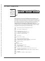
5.3. MARQUEE CONTROLLER
(UP TO 32 DISPLAYS)
MARQUEE DISPLAY
ADDR: 1
MARQUEE DISPLAY
ADDR: 2
MARQUEE DISPLAY
ADDR: 127
RS 422
P
L
C
MARQUEE CONTROLLER
Marquee displays can be connected to the Total Control Products host device called
a Marquee Controller (SM1000SMC). The Marquee Controller stores up to 1022
unique messages each with their own unique message attributes in its 31K of user
memory.
The Marquee display(s) will be connected to the SMC- and SMC+ terminals of the
Marquee Controller. Up to 32 Marquee Displays can be connected to the SMC- and
SMC+ terminals with a maximum distance of 10,000 feet without the use of in line
amplification. Using in-line RS422 amplification allows up to 123 separately
addressable Marquee Displays to be connected to the SMC-, SMC+ terminals.
MARQUEE
CONTROLLER
RS422
MARQUEE
DISPLAY
Additional Marquee Displays
can be multidropped
as shown
3
3
SMC+
11
6
6
SMC-
10
7
7
RS422 (+)
RS422 (-)
See the Marquee Controller User Manual (SM1000MMC) for more information.
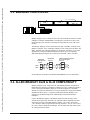
5.4. ALLEN-BRADLEY DL20 & DL40 COMPATIBILITY
Marquee Displays can be connected to the Allen-Bradley Bulletin 2706 DL20 or
DL40 Data Liner displays serial RS232 or RS422 port. Up to 32 Marquee Displays
can be connected to the RS422 output port of the DL20 display at a maximum
distance of 10,000 feet without the use of in-line amplification. Using in-line RS422
amplification allows up to 111 separately addressable Marquee Displays to be
connected to the RS422 output of the Allen-Bradley DL20 without distance
limitations.
Connect the Marquee Display to the RS422 output of the DL20 using a 100%
shielded twisted pair cable with drain wire. Marquee address and baud rates must
match those selected on the DL20 hardware and the ``out to slave" and correct
``slave number" must be programmed as message attributes. Also, be sure to select
the correct character height on the Marquee. See the chart at the end of this section
for setting the character mode.
QUICKMARQUEE DISPLAY
41
Courtesy of Steven Engineering, Inc. Ÿ 230 Ryan Way, South San Francisco, CA, 94080-6370 Ÿ Main Office: (650) 588-9200 Ÿ Outside Local Area: (800) 258-9200 Ÿ www.stevenengineering.com
ALLEN-BRADLEY
DL20
MARQUEE
DISPLAY
Additional Marquee Displays
can be multidropped
as shown
3
3
RS422 +
5
6
6
RS422 -
4
7
7
RS422 (+)
RS422 (-)
Note that it is also possible to use the RS232 output of the DL20 to connect to one
Marquee Display, however, the distance limitation is 50 feet.
When slaving a Marquee Display from a DL20 or DL40, Marquee selection is very
important. Below is a chart showing which Marquee can be used for each Dataliner
configuration.
DATALINER
MARQUEE
MARQUEE
# OF LINES
2.1” CHAR. MODE
4.8” CHAR. MODE
1
SM1202FOA
QM1204ROA
2
QM1104ROA
QM2204ROA
4
QM2104ROA
QM4204ROA
When using the Dataliner displays with a Marquee, avoid using scroll mode since this
tends to slow the update time to the Marquee Display.
5.5. SMART SIM & SMART MC COMPATIBILITY
Marquee Displays can be connected to the SMART SIM or SMART MC displays
serial RS232 or RS422 on port 3. Up to 32 Marquee Displays can be connected to
the RS422 output port of the display at a maximum distance of 10,000 feet without
the use of in-line amplification. Using in-line RS422 amplification allows up to 111
separately addressable Marquee Displays to be connected to the RS422 output
without distance limitations.
Connect the Marquee Display to the port 3 RS422 output using a 100% shielded
twisted pair cable with drain wire. Marquee address and baud rates must match those
selected in the host display and the ``out to slave" and correct ``slave number" must
be programmed as message attributes. Also, be sure to select the correct character
height on the Marquee. See the chart at the end of this section for setting the
character mode.
42
Additional Marquee Displays
can be multidropped
as shown
SMART SIM OR
SMART MC
PORT 3
MARQUEE
DISPLAY
3
3
RS422 +
6
6
RS422 -
7
7
RS422 (+)
RS422 (-)
QUICKMARQUEE DISPLAY
Courtesy of Steven Engineering, Inc. Ÿ 230 Ryan Way, South San Francisco, CA, 94080-6370 Ÿ Main Office: (650) 588-9200 Ÿ Outside Local Area: (800) 258-9200 Ÿ www.stevenengineering.com
Note that it is also possible to use the RS232 port 3 output of the SIM/MC to connect
to one Marquee Display, however, the distance limitation is 50 feet.
When slaving a Marquee Display from a SIM or MC, Marquee selection is very
important. Below is a chart showing which Marquee can be used for each display
configuration.
SIM / MC
MARQUEE
MARQUEE
# OF LINES
2.1” CHAR. MODE
4.8” CHAR. MODE
1
SM1202FOA
QM1204ROA
2
QM1104ROA
QM2204ROA
4
QM2104ROA
QM4204ROA
When using the SIM or MC with a Marquee, avoid using scroll mode since this tends
to slow the update time to the Marquee Display.
This page intentionally left blank.
QUICKMARQUEE DISPLAY
43
Courtesy of Steven Engineering, Inc. Ÿ 230 Ryan Way, South San Francisco, CA, 94080-6370 Ÿ Main Office: (650) 588-9200 Ÿ Outside Local Area: (800) 258-9200 Ÿ www.stevenengineering.com
Courtesy of Steven Engineering, Inc. Ÿ 230 Ryan Way, South San Francisco, CA, 94080-6370 Ÿ Main Office: (650) 588-9200 Ÿ Outside Local Area: (800) 258-9200 Ÿ www.stevenengineering.com
6. MAINTENANCE
6.1. CLEANING THE LENS
The lens should be cleaned using a soft cloth or paper towel and a non-abrasive
cleaner. Avoid using industrial strength cleaners as they may react with the lens and
cause the lens to blur the display.
6.2. FACTORY REPAIRS
This equipment has been tested and burned-in to reduce the occurrence of field
failures. In the event you experience a problem with this unit, contact the customer
service department for assistance. The phone number is located on the front cover of
this manual. This unit is not field repairable and must be returned to the factory or
authorized repair depot.
RETURN OF EQUIPMENT: UNDER NO CIRCUMSTANCES IS EQUIPMENT
TO BE RETURNED WITHOUT FIRST OBTAINING PERMISSION AND A
RETURN MATERIAL AUTHORIZATION NUMBER.
This page intentionally left blank.
QUICKMARQUEE DISPLAY
45
46
QUICKMARQUEE DISPLAY
Courtesy of Steven Engineering, Inc. Ÿ 230 Ryan Way, South San Francisco, CA, 94080-6370 Ÿ Main Office: (650) 588-9200 Ÿ Outside Local Area: (800) 258-9200 Ÿ www.stevenengineering.com
Courtesy of Steven Engineering, Inc. Ÿ 230 Ryan Way, South San Francisco, CA, 94080-6370 Ÿ Main Office: (650) 588-9200 Ÿ Outside Local Area: (800) 258-9200 Ÿ www.stevenengineering.com
APPENDIX A: ASCII CHARACTER CODE TABLE
QUICKMARQUEE DISPLAY
Decimal
Oct.
Hex
Binary
0
1
2
3
4
5
6
7
8
9
10
11
12
13
14
15
16
17
18
19
20
21
22
23
24
25
26
27
28
29
30
31
32
33
34
35
36
37
38
39
40
41
42
43
44
45
46
47
48
49
50
000
001
002
003
004
005
006
007
010
011
012
013
014
015
016
017
020
021
022
023
024
025
026
027
030
031
032
033
034
035
036
037
040
041
042
043
044
045
046
047
050
051
052
053
054
055
056
057
060
061
062
00
01
02
03
04
05
06
07
08
09
0A
0B
0C
0D
0E
0F
10
11
12
13
14
15
16
17
18
19
1A
1B
1C
1D
1E
1F
20
21
22
23
24
25
26
27
28
29
2A
2B
2C
2D
2E
2F
30
31
32
00000000
00000001
00000010
00000011
00000100
00000101
00000110
00000111
00001000
00001001
00001010
00001011
00001100
00001101
00001110
00001111
00010000
00010001
00010010
00010011
00010100
00010101
00010110
00010111
00011000
00011001
00011010
00011011
00011100
00011101
00011110
00011111
00100000
00100001
00100010
00100011
00100100
00100101
00100110
00100111
00101000
00101001
00101010
00101011
00101100
00101101
00101110
00101111
00110000
00110001
00110010
Printed
Character
Control
Code
NUL
SOH
STX
ETX
EOT
ENQ
ACK
BEL
BS
HT
LF
VT
FF
CR
SO
SI
DLE
DC1
DC2
DC3
DC4
NAK
SYN
ETB
CAN
EM
SUB
ESC
FS
GS
RS
US
SP
!
"
#
$
%
&
'
)
(
*
+
,
.
/
0
1
2
CTRL 0
CTRL A
CTRL B
CTRL C
CTRL D
CTRL E
CTRL F
CTRL G
CTRL H
CTRL I
CTRL J
CTRL K
CTRL L
CTRL M
CTRL N
CTRL O
CTRL P
CTRL Q
CTRL R
CTRL S
CTRL T
CTRL U
CTRL V
CTRL W
CTRL X
CTRL Y
CTRL Z
Escape
CTRL ,
CTRL CTRL .
CTRL /
47
Courtesy of Steven Engineering, Inc. Ÿ 230 Ryan Way, South San Francisco, CA, 94080-6370 Ÿ Main Office: (650) 588-9200 Ÿ Outside Local Area: (800) 258-9200 Ÿ www.stevenengineering.com
Decimal
51
52
53
54
55
56
57
58
59
60
61
62
63
64
65
66
67
68
69
70
71
72
73
74
75
76
77
78
79
80
81
82
83
84
85
86
87
88
89
90
91
92
93
94
95
96
97
98
99
100
48
Oct.
Hex
Binary
063
064
065
066
067
070
071
072
073
074
075
076
077
100
101
102
103
104
105
106
107
110
111
112
113
114
115
116
117
120
121
122
123
124
125
126
127
130
131
132
133
134
135
136
137
140
141
142
143
144
33
34
35
36
37
38
39
3A
3B
3C
3D
3E
3F
40
41
42
43
44
45
46
47
48
49
4A
4B
4C
4D
4E
4F
50
51
52
53
54
55
56
57
58
59
5A
5B
5C
5D
5E
5F
60
61
62
63
64
00110011
00110100
00110101
00110110
00110111
00111000
00111001
00111010
00111011
00111100
00111101
00111110
00111111
01000000
01000001
01000010
01000011
01000100
01000101
01000110
01000111
01001000
01001001
01001010
01001011
01001100
01001101
01001110
01001111
01010000
01010001
01010010
01010011
01010100
01010101
01010110
01010111
01011000
01011001
01011010
01011011
01011100
01011101
01011110
01011111
01100000
01100001
01100010
01100011
01100100
Printed
Character
Control
Code
3
4
5
6
7
8
9
:
;
<
=
>
?
@
A
B
C
D
E
F
G
H
I
J
K
L
M
N
O
P
Q
R
S
T
U
V
W
X
Y
Z
[
\
]
^
_
\
a
b
c
d
QUICKMARQUEE DISPLAY
Courtesy of Steven Engineering, Inc. Ÿ 230 Ryan Way, South San Francisco, CA, 94080-6370 Ÿ Main Office: (650) 588-9200 Ÿ Outside Local Area: (800) 258-9200 Ÿ www.stevenengineering.com
Decimal
101
102
103
104
105
106
107
108
109
110
111
112
113
114
115
116
117
118
119
120
121
122
123
124
125
126
127
QUICKMARQUEE DISPLAY
Oct.
Hex
Binary
145
146
147
150
151
152
153
154
155
156
157
160
161
162
163
164
165
166
167
170
171
172
173
174
175
176
177
65
66
67
68
69
6A
6B
6C
6D
6E
6F
70
71
72
73
74
75
76
77
78
79
7A
7B
7C
7D
7E
7F
01100101
01100110
01100111
01101000
01101001
01101010
01101011
01101100
01101101
01101110
01101111
01110000
01110001
01110010
01110011
01110100
01110101
01110110
01110111
01111000
01111001
01111010
01111011
01111100
01111101
01111110
01111111
Printed
Character
Control
Code
e
f
g
h
i
j
k
l
m
n
o
p
q
r
s
t
u
v
w
x
y
z
{
|
}
~
DEL
49