1
User Manual
ProDAQ 3416
16-Channel 24-bit Sigma-Delta
ADC Function Card
PUBLICATION NUMBER: 3416-XX-UM-1010
Copyright, © 2014, Bustec Production, Ltd.
Bustec Production, Ltd.
Bustec House, Shannon Business Park, Shannon, Co. Clare, Ireland
Tel: +353 (0) 61 707100, FAX: +353 (0) 61 707106
PROPRIETARY NOTICE
This document and the technical data herein disclosed, are proprietary to Bustec
Production Ltd., and shall not, without express written permission of Bustec
Production Ltd, be used, in whole or in part to solicit quotations from a competitive
source or used for manufacture by anyone other than Bustec Production Ltd. The
information herein has been developed at private expense, and may only be used for
operation and maintenance reference purposes or for purposes of engineering
evaluation and incorporation into technical specifications and other documents,
which specify procurement of products from Bustec Production Ltd. This document
is subject to change without further notification. Bustec Production Ltd. reserves the
right to change both the hardware and software described herein.
ProDAQ 3416 Function Card User Manual
3416-XX-UM
Table of Contents
1.
INTRODUCTION ........................................................................................................... 9
2.
INSTALLATION .......................................................................................................... 11
2.1. Unpacking and Inspection ..................................................................................... 11
2.2. Reshipment Instructions ........................................................................................ 11
2.3. ProDAQ VXIbus Module Installation ...................................................................... 12
2.3.1. Preparing the ProDAQ Module ....................................................................... 12
2.3.2. Installing a ProDAQ Function Card ................................................................. 13
2.3.3. Removing a ProDAQ Function Card ............................................................... 15
2.4. ProDAQ LXI Function Card Carrier Installation ..................................................... 15
2.4.1. Opening the ProDAQ 6100 Enclosure ............................................................ 15
2.4.2. Installing a ProDAQ Function Card ................................................................. 17
2.4.3. Removing a ProDAQ Function Card ............................................................... 19
2.4.4. Closing the ProDAQ 6100 Enclosure .............................................................. 20
3.
THEORY OF OPERATION ......................................................................................... 23
3.1.
3.2.
3.3.
3.4.
3.5.
3.6.
3.7.
4.
SPECIFICATIONS ...................................................................................................... 27
4.1.
4.2.
4.3.
4.4.
4.5.
5.
Block Diagram ....................................................................................................... 23
Analog Front-End Circuitry .................................................................................... 23
TEDS Reader Interface ......................................................................................... 24
I2C Master Interface............................................................................................... 24
Data Acquisition..................................................................................................... 25
Sampling Settings.................................................................................................. 26
Multiple Cards Synchronization ............................................................................. 26
Input Characteristics .............................................................................................. 27
Sampling ............................................................................................................... 28
Triggering .............................................................................................................. 28
Synchronization ..................................................................................................... 28
Environmental Specifications ................................................................................ 28
THE VXIPLUG&PLAY DRIVER .................................................................................. 29
5.1. Installation ............................................................................................................. 29
5.2. The Soft Front Panel ............................................................................................. 29
5.2.1. “Waveforms” Tab ............................................................................................ 31
5.2.2. “Channels” Tab ............................................................................................... 31
5.2.3. “Acquisition” Tab ............................................................................................. 32
6.
PROGRAMMING THE PRODAQ 3416 ....................................................................... 33
6.1. VXIplug&play Driver Organization ......................................................................... 33
6.2. Connecting to the Function Card ........................................................................... 34
6.3. Hardware Configuration ......................................................................................... 35
6.4. Single-Card Acquisition ......................................................................................... 35
6.4.1. Single-shot Acquisition .................................................................................... 35
6.4.2. Continuous Acquisition ................................................................................... 37
Copyright,
2014 Bustec Production Ltd.
Page 3 of 171
3416-XX-UM
ProDAQ 3416 Function Card User Manual
6.5. Calibration ............................................................................................................. 39
APPENDIX A: FRONT-PANEL CONNECTOR ................................................................ 41
APPENDIX B: REGISTER DESCRIPTION...................................................................... 43
B.1
B.2
B.3
B.4
B.5
B.6
B.7
B.8
B.9
B.10
B.11
B.12
B.13
B.14
B.15
B.16
B.17
B.18
B.19
B.20
B.21
B.22
B.23
B.24
B.25
B.26
B.27
FCID (0x0) – Function Card ID Register................................................................ 45
FCVER (0x1) – Function Card Version Register ................................................... 45
FCCSR (0x2) – Function Card Control and Status Register ................................. 45
MODE1 (0x3) – Mode 1 Register .......................................................................... 47
MODE2 (0x4) – Mode 2 Register .......................................................................... 48
OTRI (0x5) – Output Trigger Configuration Register ............................................. 49
ITRI (0x6) – Input Trigger Status Register ............................................................. 50
DDS_WX (0x8) – DDS Control Register ............................................................... 52
OCOEFL (0x9) – Offset Coefficient Write Low Register ........................................ 52
OCOEFH (0xA) – Offset Coefficient Write High Register ................................... 52
GCOEFL (0xB) – Gain Coefficient Write Low Register ...................................... 53
GCOEFH (0xC) – Gain Coefficient Write High Register .................................... 53
I2C_CTRL (0xE) – I2C Control Register ............................................................ 54
TEDS_ACC (0xF) – TEDS Access Register ...................................................... 54
FIFO_CTRL (0x10) – FIFO Control Register...................................................... 55
FIFO_AFT (0x11) – FIFO Almost Full Flag Threshold Register ......................... 56
FIFO_WR (0x12) – FIFO Write Register ............................................................ 56
SIG_ERR (0x13) – Signal Error Register ........................................................... 56
GAIN_COMP (0x14) – Gain Compensation Register......................................... 57
ERROR (0x15) – Error Register ......................................................................... 57
POSTT_NOSL (0x19) – Post Trigger Number of Scans Low Register .............. 58
POSTT_NOSH (0x1A) – Post Trigger Number of Scans High Register ............ 58
CHNxCFG (0x20…0x2F) – Channel x Configuration Register ........................... 59
FCSSUB (0xFC) – Function Card Sub-Type Register ....................................... 59
FCSERH (0xFE) – Function Card Serial Number High Register ........................ 59
FCSERL (0xFF) – Function Card Serial Number Low Register ......................... 60
FIFO (0x8000) – FIFO memory .......................................................................... 60
APPENDIX C: VXIPLUG&PLAY DRIVER FUNCTIONS ................................................. 61
C.1 Introduction ............................................................................................................ 61
C.2 Assumptions .......................................................................................................... 61
C.3 Error and Status Information: ................................................................................ 61
C.4 Function Tree Layout: ........................................................................................... 62
C.5 VXIplug&play Driver Function Details .................................................................... 64
C.5.1 bu3416_acquireWaveform .............................................................................. 64
C.5.2 bu3416_acquireWaveforms ............................................................................ 66
C.5.3 bu3416_armDAQ ............................................................................................ 69
C.5.4 bu3416_burnTEDS_OTP_ROM ..................................................................... 70
C.5.5 bu3416_calibrateAllChannels ......................................................................... 71
C.5.6 bu3416_calibrateBoard ................................................................................... 72
C.5.7 bu3416_checkAcquisition ............................................................................... 73
C.5.8 bu3416_checkMultAcquisition ........................................................................ 75
C.5.9 bu3416_clearErrors ........................................................................................ 77
C.5.10 bu3416_close .............................................................................................. 78
Page 4 of 171
Copyright,
2014 Bustec Production Ltd.
ProDAQ 3416 Function Card User Manual
C.5.11
C.5.12
C.5.13
C.5.14
C.5.15
C.5.16
C.5.17
C.5.18
C.5.19
C.5.20
C.5.21
C.5.22
C.5.23
C.5.24
C.5.25
C.5.26
C.5.27
C.5.28
C.5.29
C.5.30
C.5.31
C.5.32
C.5.33
C.5.34
C.5.35
C.5.36
C.5.37
C.5.38
C.5.39
C.5.40
C.5.41
C.5.42
C.5.43
C.5.44
C.5.45
C.5.46
C.5.47
C.5.48
C.5.49
C.5.50
C.5.51
C.5.52
C.5.53
C.5.54
C.5.55
C.5.56
C.5.57
C.5.58
C.5.59
C.5.60
Copyright,
3416-XX-UM
bu3416_enableLIST .................................................................................... 79
bu3416_error_message............................................................................... 80
bu3416_error_query .................................................................................... 81
bu3416_fcSelect .......................................................................................... 82
bu3416_generateITRI .................................................................................. 83
bu3416_generateOTRI ................................................................................ 84
bu3416_getADCMode ................................................................................. 85
bu3416_getBufferSize ................................................................................. 87
bu3416_getCalibData .................................................................................. 88
bu3416_getDAQMode ................................................................................. 90
bu3416_getDAQStatus ................................................................................ 92
bu3416_getDDSFreq ................................................................................... 94
bu3416_getFIFOConfig ............................................................................... 95
bu3416_getFIFOStatus ............................................................................... 96
bu3416_getFPTrigPolarity ........................................................................... 97
bu3416_getITRIConfig ................................................................................ 99
bu3416_getITRIState ................................................................................ 100
bu3416_getMultFCsession ........................................................................ 101
bu3416_getOTRIConfig ............................................................................. 103
bu3416_getPostScans .............................................................................. 106
bu3416_getSampFreq ............................................................................... 107
bu3416_getSerNum .................................................................................. 108
bu3416_init ................................................................................................ 109
bu3416_multClose ..................................................................................... 111
bu3416_multConfig ................................................................................... 112
bu3416_multInit ......................................................................................... 115
bu3416_paramInit ...................................................................................... 118
bu3416_readAcquisition ............................................................................ 120
bu3416_readFIFO ..................................................................................... 122
bu3416_readMultAcquisition ..................................................................... 123
bu3416_readTEDS_EEPROM .................................................................. 125
bu3416_readTEDS_OTP_ROM ................................................................ 126
bu3416_readTEDS_ROM.......................................................................... 127
bu3416_reset............................................................................................. 128
bu3416_resetDAQ ..................................................................................... 129
bu3416_resetFIFO .................................................................................... 130
bu3416_resetI2C ....................................................................................... 131
bu3416_resizeMultBuf ............................................................................... 132
bu3416_revision_query ............................................................................. 133
bu3416_self_test ....................................................................................... 134
bu3416_setAcquisitionMode ..................................................................... 135
bu3416_setADCMode ............................................................................... 137
bu3416_setBufferSize ............................................................................... 139
bu3416_setChanConfig ............................................................................. 140
bu3416_setDAQMode ............................................................................... 142
bu3416_setDDSFreq ................................................................................. 144
bu3416_setFIFOConfig ............................................................................. 145
bu3416_setFPTrigPolarity ......................................................................... 146
bu3416_setITRIConfig ............................................................................... 148
bu3416_setMultChanConfig ...................................................................... 150
2014 Bustec Production Ltd.
Page 5 of 171
3416-XX-UM
ProDAQ 3416 Function Card User Manual
C.5.61
C.5.62
C.5.63
C.5.64
C.5.65
C.5.66
C.5.67
C.5.68
C.5.69
C.5.70
C.5.71
C.5.72
C.5.73
C.5.74
C.5.75
bu3416_setMultTrigConfig......................................................................... 152
bu3416_setOTRIConfig ............................................................................. 153
bu3416_setPostScans ............................................................................... 156
bu3416_setSampFreq ............................................................................... 157
bu3416_setTrigConfig ............................................................................... 158
bu3416_startAcquisition ............................................................................ 159
bu3416_startAcquisitionEx ........................................................................ 160
bu3416_startMultAcquisition...................................................................... 161
bu3416_startMultAcquisitionEx ................................................................. 162
bu3416_stopAcquisition ............................................................................ 163
bu3416_stopDAQ ...................................................................................... 164
bu3416_stopMultAcquisition ...................................................................... 165
bu3416_storeCalibData ............................................................................. 166
bu3416_writeReadI2C ............................................................................... 168
bu3416_writeTEDS_EEPROM .................................................................. 169
Page 6 of 171
Copyright,
2014 Bustec Production Ltd.
ProDAQ 3416 Function Card User Manual
3416-XX-UM
Table of Figures
Figure 1 – Removing the ProDAQ module cover .............................................................. 12
Figure 2 – The ProDAQ module assembly ......................................................................... 14
Figure 3 – Simplified Block Diagram................................................................................... 23
Figure 4 – Analog front-end circuitry (single channel) ........................................................ 24
Figure 5 - Selecting the Connection Method ...................................................................... 29
Figure 6 – Specifying the Function Card Address .............................................................. 30
Figure 7 - ProDAQ 3416 Soft Front Panel Application ....................................................... 30
Figure 8 – Channel Configuration ....................................................................................... 31
Figure 9 – Acquisition Configuration ................................................................................... 32
Figure 10 – VXIplug&play Driver Organization ................................................................... 33
Figure 11 - Opening a Session ........................................................................................... 34
Figure 12 – Acquiring a Waveform ..................................................................................... 36
Figure 13 – Starting the Asynchronous Acquisition ............................................................ 37
Figure 14 – Checking the Status of the Acquisition and Data Read-out ............................. 38
Figure 15 - Front panel connector as seen when the card is fitted in the module. ............. 41
Copyright,
2014 Bustec Production Ltd.
Page 7 of 171
3416-XX-UM
ProDAQ 3416 Function Card User Manual
Reference Documents
Title
Number
3180-XX-UM
6100-XX-UM
ProDAQ 3180 User Manual
ProDAQ 6100 User Manual
Glossary
ADC
:
Analog-to-Digital Converter
CRD
:
Current Regulator Diode
DA
:
Data Acquisition
DAC
:
Digital-to-Analog Converter
DDS
:
Direct Digital Synthesis
DTC
:
Discharge Time Constant
ECL
:
Emitter-Coupled Logic
FIR
:
Finite Impulse Response digital filter
FPGA
:
Field Programmable Gate Array
H
:
State of the bit(s) defined by hardware (in register description)
ICP
:
Integrated Circuit Piezoelectric
LED
:
Light Emitting Diode
LVDS
:
Low Voltage Differential Signal(ing)
LXI
:
LAN eXtensions for Instrumentation
PCB
:
Printed Circuit Board
PGA
:
Programmable Gain Amplifier
PLL
:
Phase-Locked Loop
RO
:
Read-only access to register
R/W
:
Read/Write access to register
R/WSC
:
Read/Write access to register, Self-Clear after operation finished
TEDS
:
Transducer Electronic Data Sheet
VREF
:
Voltage Reference
VXI
:
VME eXtensions for Instrumentation
WO
:
Write-only access to register
Page 8 of 171
Copyright,
2014 Bustec Production Ltd.
ProDAQ 3416 Function Card User Manual
3416-XX-UM
1. Introduction
The ProDAQ 3416 function card is a 16-channel, 24-bit Sigma-Delta Analog-to-Digital converter
function card. It is an add-on card to use together with ProDAQ motherboards and function card
carriers.
It provides the following features:
16 analog channels with 24-bit resolution
Simultaneous sampling
Max. Input Range 10V with overvoltage protection
Programmable gains of 1, 2, 5, 10, 20, 50, 100, 200, 500, 1000 and 2000
User programmable any sampling rate in a range from 1SPS to 10kSPS
On-board FIFO memory
Synchronization of multiple cards
I2C master controller for an external signal conditioning unit
IEEE 1451.4 (TEDS) Smart Transducer Interface support
Copyright,
2014 Bustec Production Ltd.
Page 9 of 171
3416-XX-UM
ProDAQ 3416 Function Card User Manual
This page was intentionally left blank.
Page 10 of 171
Copyright,
2014 Bustec Production Ltd.
ProDAQ 3416 Function Card User Manual
3416-XX-UM
2. Installation
ProDAQ function cards can be installed in
Function Card Carriers. If you ordered your
motherboard or carrier, the function cards will
install additional cards or exchange installed
procedure.
ProDAQ VXIbus Motherboards and ProDAQ LXI
ProDAQ function card together with the ProDAQ
be pre-installed to your specification. If you want to
cards, use the following disassembling/assembling
2.1. Unpacking and Inspection
The ProDAQ instrument is shipped in an antistatic package to prevent any damage from
electrostatic discharge (ESD). Proper ESD handling procedures must always be used when
packing, unpacking or installing any ProDAQ module, ProDAQ plug-in module or ProDAQ function
card:
Ground yourself via a grounding strap or similar, e.g. by holding to a grounded object.
Discharge the package by touching it to a grounded object, e.g. a metal part of your VXIbus
chassis, before removing the module from the package.
Remove the ProDAQ instrument from its carton, preserving the factory packaging as much
as possible.
Inspect the ProDAQ instrument for any defect or damage. Immediately notify the carrier if
any damage is apparent.
2.2. Reshipment Instructions
Use the original packing material when returning a ProDAQ instrument to Bustec Production Ltd.
for calibration or servicing. The original shipping carton and the instrument's plastic foam will
provide the necessary support for safe reshipment.
If the original anti-static packing material is unavailable, wrap the ProDAQ instrument in anti-static
plastic sheeting and use plastic spray foam to surround and protect the instrument. Reship in either
the original or new shipping carton.
WARNING
Proper ESD handling procedures must always be used when packing, unpacking or
installing any ProDAQ device or ProDAQ function card. Ground yourself via a
grounding strap or similar, e.g. by holding to a grounded object and discharge the
package by touching it to a grounded object, before removing the module from the
package.
Copyright,
2014 Bustec Production Ltd.
Page 11 of 171
3416-XX-UM
ProDAQ 3416 Function Card User Manual
2.3. ProDAQ VXIbus Module Installation
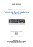
2.3.1. Preparing the ProDAQ Module
To install a ProDAQ function card into one of the ProDAQ motherboards, you need to remove the
module’s top cover:
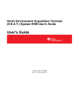
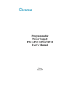
1 - Module Cover
2 - Cover Screws
3 - Cover Hooks
Figure 1 – Removing the ProDAQ module cover
To remove the top cover, remove the one countersunk screw in the back and the two panhead
screws towards the front panel (), that hold the cover in place. Remove the cover by sliding it out
of its position towards the VXIbus connectors and up. Take special care about the hooks ()
holding it in place. Try not to lift the cover straight up. See Figure 1 for the location of the screws.
To re-install the cover, slide it back into its position by placing the small hooks over their holes and
moving the cover down and forward. Secure the top cover using two panhead screws and one
countersunk screw ().
Page 12 of 171
Copyright,
2014 Bustec Production Ltd.
ProDAQ 3416 Function Card User Manual
3416-XX-UM
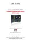
2.3.2. Installing a ProDAQ Function Card
The single-width ProDAQ function cards are arranged inside the ProDAQ module in four stacks of
two cards each. The double-width ProDAQ function cards are arranged inside the ProDAQ module
in two stacks of two cards each. The function cards are mounted face down, e.g. the front-panel
connectors as well as the motherboard connectors are underneath the PCB. Single-width and
double-width ProDAQ function cards can be mixed in the ProDAQ module. The ProDAQ 3416
function card is a single-width card.
To install a single-width ProDAQ function card in any of the possible positions, use the following
procedure (See
Figure 2 for reference):
Remove the top cover of the module as described earlier in this chapter (Fig. 2, Pos. 1).
Remove all screws on the front-panel holding installed function cards or double filler
panels in place (Fig. 2, Pos. 2). Screws holding single filler panels don't need to be
removed.
Remove the two panhead screws that mount the front panel to the modules bottom cover
(Fig. 2, Pos. 6).
Please take special care of the module handles and the rings (Fig. 2, Pos. 3 and 4), which
are also fixed by those screws. The mounting angle (Fig. 2, Pos. 5) stays fixed to the front
panel.
Remove the front panel by moving it forward carefully so as to avoid bending the installed
function cards.
Choose the stack and position (lower or upper) where you want to mount the function
card. If the stack, in which the function card should be installed, is covered by a double
filler panel, you have to remove it before installing the function card.
Remove the three 2.5mm panhead screws and the crinkle washers from the stack's
standoffs (Fig. 2, Pos. 9 and 10 for example).
If you want to install a function card in the upper position of a stack without having a
function card in the lower position, you need to mount both spacers (Fig. 3, Pos. 11) on
each standoff. If the stack is already populated with a function card in the lower position,
mount only the bigger spacer (Fig. 2, Pos. 8) onto each standoff.
Place a bayonet (supplied) on each standoff. Align the function card over these and slide
carefully down. The function card should be held parallel to the modules bottom cover all
the time during its way down.
Fix the function card by mounting the three 2.5mm panhead screws and the crinkle
washers onto each standoff. If you install a function card in the lower position of a stack,
you need first to mount both spacers (Fig. 2, Pos. 11) onto each standoff.
Re-mount the modules front-panel. If there is only one function card mounted in a stack,
cover the remaining opening in the front panel by a single filler panel.
Re-mount the modules top cover.
Adjust the procedure respectively for a double-width ProDAQ function card.
Copyright,
2014 Bustec Production Ltd.
Page 13 of 171
3416-XX-UM
ProDAQ 3416 Function Card User Manual
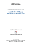
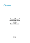
1
10
9
8
7
11
2
6
3
5
4
1 - 2.5mm Panhead Screws
4 - Ring
7 - Standoff
10 - 2.5mm Panhead Screw
2 - 2.5mm Panhead Screws
5 - Mounting Angle
8 - Spacer
11 - 2mm Spacer
3 - Module Handle
6 - 2.5mm Panhead Screws
9 - Crinkle Washer
Figure 2 – The ProDAQ module assembly
Page 14 of 171
Copyright,
2014 Bustec Production Ltd.
ProDAQ 3416 Function Card User Manual
3416-XX-UM
2.3.3. Removing a ProDAQ Function Card
Removing a ProDAQ function card is exactly the reverse operation then installing it. After removing
the top cover and the front panel as described previously, remove the three roundhead screws that
fix the function card(s) on the standoffs.
Take special care when removing the function card(s) not to bend the motherboard connectors.
After removing the function card(s), install the correct combination of spacers on the standoffs. If a
stack is populated with only one function card, each of the standoffs needs to be mounted with
both spacers to cover the distance between the cards as well as the PCB thickness of the missing
card. If a stack is populated with two function cards, only the bigger spacer must be mounted.
Fix any remaining function cards again by mounting the three panhead screws on the standoffs, remount the front panel and the modules cover.
2.4. ProDAQ LXI Function Card Carrier Installation
WARNING
Disconnect the ProDAQ 6100 from the mains before opening the enclosure!
2.4.1. Opening the ProDAQ 6100 Enclosure
Remove the up to eight M2.5x6mm Pozidrive Panhead screws () attaching the front bezel to the
function cards (If there is no function card installed in a slot and a blanking panel is used to cover
the front bezel opening, do not remove it screws before detaching the front bezel). Then remove
the two M3x6mm Torx Countersunk screws () attaching the front bezel to the enclosure.
Copyright,
2014 Bustec Production Ltd.
Page 15 of 171
3416-XX-UM
ProDAQ 3416 Function Card User Manual
Slide the front bezel off () as shown below:
Remove the M3x6mm Torx Countersunk screw () attaching the function card cover to the
enclosure:
Page 16 of 171
Copyright,
2014 Bustec Production Ltd.
ProDAQ 3416 Function Card User Manual
3416-XX-UM
Slide the function card cover off () as shown below:
2.4.2. Installing a ProDAQ Function Card
To install a ProDAQ Function Card into the ProDAQ 6100 LXI Function Card Carrier, you must first
remove the front bezel and the function card cover as shown previously (see paragraph 2.4.1
Opening the ProDAQ 6100 Enclosure). The ProDAQ Function Cards are mounted inside the
ProDAQ 6100 directly on the main PCB. The function cards positions two and four are located on
top of the PCB and the positions one and three below. The function cards are mounted face down,
e.g. the front-panel connectors as well as the motherboard connectors are underneath the PCB
when mounted. Make sure that the M3x6mm screws and washers are removed from the PCB
standoffs ():
Copyright,
2014 Bustec Production Ltd.
Page 17 of 171
3416-XX-UM
ProDAQ 3416 Function Card User Manual
Position the function card over the function card slot you want to install it to (), carefully aligning
the connectors connecting it to the ProDAQ 6100 PCB and push it down until it seats fully onto the
standoffs of the ProDAQ 6100 PCB:
Use three M3x6mm panhead screws and washers () to attach the function card to the ProDAQ
6100 PCB (six screws and washers for a double wide function card):
Page 18 of 171
Copyright,
2014 Bustec Production Ltd.
ProDAQ 3416 Function Card User Manual
3416-XX-UM
2.4.3. Removing a ProDAQ Function Card
If you need to remove an installed function card, remove the three M3x6mm screws () mounting
them to the base board (six M3x6mm screws for a double wide function card.
Remove the function card by pulling it () straight and evenly upward (or downward for a function
card mounted on the bottom of the main PCB). Do not tilt the function card when doing so as it
might damage the connectors connecting it to the ProDAQ 6100 PCB.
Copyright,
2014 Bustec Production Ltd.
Page 19 of 171
3416-XX-UM
ProDAQ 3416 Function Card User Manual
2.4.4. Closing the ProDAQ 6100 Enclosure
To close the enclosure after installing or removing a ProDAQ function card, first slide back on the
function card cover ():
and attach it with a M3x6mm Torx screw to the enclosure:
Page 20 of 171
Copyright,
2014 Bustec Production Ltd.
ProDAQ 3416 Function Card User Manual
3416-XX-UM
Make sure that the cutouts for the function card connectors in the front bezel are properly opened
or covered by filler panels to match the installed function cards. Slide the front bezel back on ()
and attach it to the enclosure by two M3x6 Torx screws
Copyright,
2014 Bustec Production Ltd.
Page 21 of 171
3416-XX-UM
ProDAQ 3416 Function Card User Manual
This page was intentionally left blank.
Page 22 of 171
Copyright,
2014 Bustec Production Ltd.
ProDAQ 3416 Function Card User Manual
3416-XX-UM
3. Theory of Operation
3.1. Block Diagram
Front-End Circuit
Channel #1
ADC
Front-End Circuit
Channel #2
ADC
Front-End Circuit
Channel #3
ADC
ADC Data
Register
FIR Filter and
Decimation Stage #1
FIR Filter and
Decimation Stage #2
MUX
FIFO
ADC
Front-End Circuit
Channel #5
ADC
DA Control
Front-End Circuit
Channel #15
ADC
Front-End Circuit
Channel #16
ADC
FC Connector
FIR Filter and
Decimation Stage #3
Front-End Circuit
Channel #4
Internal
Registers
Synchronization
System
External
SYNC I/O
Front Panel
I2C connection
Clock Generation
(PLL and DDS)
I2C Master
Controller
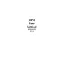
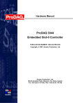
Figure 3 – Simplified Block Diagram
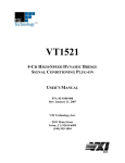
3.2. Analog Front-End Circuitry
The ProDAQ 3416 features sixteen fully differential, overvoltage protected, high impedance analog
input channels numbered from 1 to 16. Analog front end circuitry condition the input signal, which is
later digitized by an ADC.
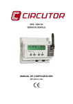
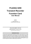
Figure 3 shows a block diagram of the analog front end circuitry for a single channel. The input
signal is first passed through an optional attenuator stage designed to allow for voltages of up to
60V. For calibration purposes, the input of every channel can be connected to the voltage
reference bus available on ProDAQ motherboards and function card carriers via a 2:1 multiplexer.
The gain block consists of multiple stages providing gain factors of 1, 2, 5, 10, 20, 50, 100, 200,
500, 1000 and 2000; independently software selectable on a per-channel basis. In the following
ADC driver block a combined differential driver, level shifter and Butterworth filter in MFB topology
prepares the signal to be digitized by the 24-bit ADC available per channel.
Copyright,
2014 Bustec Production Ltd.
Page 23 of 171
3416-XX-UM
ProDAQ 3416 Function Card User Manual
2.5V
Vref
Gain Block
HV Attenuation
LNF
2:1 Mux
IN+
AD8253
IN-
Div2
IN+
Differential
ADC Driver
Attenuator
Level Shift
RC Filter
AD8250
IN-
AIN1P
AIN1N
AIN2P
From
VRef
Eight
Identical
Channels
per ADC
ADC
ADS1278
AIN8N
Figure 4 – Analog front-end circuitry (single channel)
3.3. TEDS Reader Interface
Transducer Electronic Data Sheet (TEDS) is a nonvolatile memory within a sensor that is utilized
for storing information about that sensor. The manufacturer of the sensor deposits into this
memory initial information such as manufacturer name, sensor type, model number, serial number,
and calibration data. Memory space allocation permits the user to add additional information such
as channel ID, location, position, direction, tag number, etc. The protocols and formats of the data
are defined by IEEE P1451.4 standard.
The sensor operates in a “mixed mode”, i.e. analog or digital fashion. In the digital mode, the
information stored in memory is downloaded. In the analog mode, the sensor functions normally,
as a measurement device. A suitable TEDS signal conditioner is used to access the memory
digitally, over the same wires ordinarily used for analog measurement signal transmission.
The 3416 card has a common TEDS reader interface circuitry for all sixteen channels. It is brought
to the front panel connector on a separate pin. To provide a class 1 TEDS interface, the TEDS line
needs to be externally multiplexed onto any of analog input lines.
3.4. I2C Master Interface
2
The card contains an I C master, which may be used to program an external signal conditioning
unit via the two wire bus. For this purpose the bus signals of the master controller are amplified and
made available on separate pins on the front panel connector.
Page 24 of 171
Copyright,
2014 Bustec Production Ltd.
ProDAQ 3416 Function Card User Manual
3416-XX-UM
3.5. Data Acquisition
The 3416 function card allows continuous digitizing of up to 16 input channels. The acquired data
is streamed into onboard FIFO memory. As each input channel uses its own ADC, all channels are
sampled simultaneously. The acquisition process can be started instantly by a host application or
by a trigger event after prior arming the acquisition process. The same applies to the end of the
acquisition; it can be stopped on a host request or after another trigger event. Alternatively the
acquisition may end after collecting a programmed number of samples. A single measurement is
possible for externally triggered measurements, in such configuration a trigger event requests a
measurement of all enabled input channels on one or more cards.
A DA (data acquisition) trigger event can start the acquisition and a following trigger event can stop
the acquisition:
Note: the active trigger edge on the above picture is a rising edge, it can be configured according
to an application needs.
Alternatively the DA trigger can act as a gate and the acquisition can take place as long as the DA
trigger is active:
Note: the active trigger level on the above picture is a logical high level, it can be configured.
A DA trigger event can also start an acquisition configured to collect a programmed number of
scans. In a default configuration it is infinity and a second DA trigger event stops the acquisition. If
a number of samples to be collected is limited than a second DA trigger does not stop the
acquisition but instead can retrigger a collection of new scans if a previous set of scans have
already been collected.
Copyright,
2014 Bustec Production Ltd.
Page 25 of 171
3416-XX-UM
ProDAQ 3416 Function Card User Manual
If a number of scans to be collected is limited and a new DA trigger event happens too early before
previous programmed number of samples has been collected an error flag will be set. The error will
not appear if a new DA trigger event comes during the last scan of the programmed set of samples
so a new acquisition can be triggered at any time after the last scan begun no matter if it has
finished yet or is still in progress.
A DA trigger input, which can start and stop the acquisition has implemented a hold off feature,
which protects against false trigger events (glitches) occurring near the functional trigger event.
The hold off time is fixed and equals to 1μs. False trigger events happening in the hold off zone will
not generate an error condition and will be safely ignored.
A data acquisition trigger can be generated internally by a software command or accepted from an
external source via the input trigger line on the front panel connector or the motherboard trigger
line on the function card interface.
3.6. Sampling Settings
The output data rate of the acquisition is common for all input channels and can be set up to 10
kSamples/sec (-Bx versions) or 1 kSample/sec (-Ax versions). The acquisition clock can be
generated onboard or can be accepted from an external source via various trigger lines. If it is
generated locally, it is generated using the Direct Digital Synthesis (DDS) technique and can be
programmed by the user with a very fine resolution, much lower than 1Hz. The locally generated
clocks on multiple 3416 or other ProDAQ function cards using the same scheme can be
synchronized to each other.
As the sigma-delta ADCs together with a fixed low-pass filter in the input stage can only sample the
input data with a rate down to TBD samples/sec, additional FIR filter stages implemented in the onboard programmable logic devices provide additional decimation to allow output data rates down to
1 Sample/sec.
3.7. Multiple Cards Synchronization
The 3416 function card samples all 16 channels simultaneously. If more than 16 channels need to
be sampled in a synchronous way and the acquisition started at the same time on all channels than
multiple cards can be synchronized together.
The ProDAQ 3416 can be set as a master or a slave. If the 3416 works in stand-alone mode it
need always to be configured as master. If a number of the 3416 cards should work in a multiplecard synchronization mode then card is configured as master and all other as slaves. For the
synchronous acquisition, the master card generates two signals, which have to be distributed to all
slaves: a clock signal and a sync signal.
Page 26 of 171
Copyright,
2014 Bustec Production Ltd.
ProDAQ 3416 Function Card User Manual
3416-XX-UM
4. Specifications
4.1. Input Characteristics
Number of Channels
16
Input Type
Differential
Coupling
DC
Full Scale Signal Ranges
±5 mV, ±10 mV, ±20 mV, ±50 mV, ±100 mV,
±200 mV, ±500 mV, ±1 V, ±2 V, ±5 V and ±10 V
(plus 5% for hardware calibration and over-range capability)
Gain Settings
1, 2, 5, 10, 20, 50, 100, 200, 500, 1000, 2000
Analog Input Filter Type
2-pole Butterworth
Input Impedance
> 10 M , 25 pF
Input Protection
±25 V
Input Offset Voltage
(typical)
±30 µV typ.
±6 µV typ.
±80 µV typ.
(gain 1)
(gain 2000)
(-Cx versions, gain 1, >25 kS/s)
Gain Error
(typical)
typ. 0.002%
typ.
0.05%
typ. 0.004%
typ.
0.1%
(gain 1)
(gain 2000)
(-Cx versions, gain 1, >25 kS/s)
(-Cx versions, gain 2000, >25 kS/s)
INL (Best Fit Method)
±0.0003% FSR typ.
±0.0012% FSR max.
DC Accuracy
±(8 + 225/gain) µV
±(20 + 600/gain) µV
±(25 + 800/gain) µV
Common-mode Rejection Ratio
87 dB typ.
106 dB typ.
(gain 1)
(gain 2000)
0.1dB Analog Passband
DC to 450 Hz
DC to 4.5 kHz
DC to 23.7 kHz
(-Ax versions)
(-Bx versions)
(-Cx versions)
3dB Analog Bandwidth (fC)
DC to 490 Hz
DC to 4.9 kHz
DC to 25.8 kHz
(-Ax versions)
(-Bx versions)
(-Cx versions)
Pass Band Ripple
±0.005 dB
Stop Band Attenuation
95 dB min.
Signal-to-Noise Ratio
105 dB typ.
Signal, Noise And Distortion
(SINAD)
100 dB typ.
Total Harmonic Distortion (THD)
-102 dB typ.
Spurious-free Dynamic Range
>103 dB
Noise
Copyright,
(97.7 Hz, -1 dBFS)
(1 kHz, -1 dBFS)
35 µV RMS typ.
0.3 µV RMS typ.
2014 Bustec Production Ltd.
(typ.)
(max.)
(max., -Cx, >25 kS/s)
(1 kHz bandwidth, gain 1)
(1 kHz bandwidth, gain 2000)
Page 27 of 171
3416-XX-UM
Crosstalk
ProDAQ 3416 Function Card User Manual
116 dB typ.
4.2. Sampling
Resolution
24 bit
ADC Type
Sigma-Delta
Output Data Rates
1 S/s to 1 kS/s (-Ax versions)
1 S/s to 10 kS/s (-Bx versions)
5 kS/s to 52 kS/s (-Cx versions)
Rate Selection Resolution
0.01 S/s
Oversampling
128 x
FIFO
10 kSamples
4.3. Triggering
Trigger Input
Motherboard or Front Panel Connector
Signal Type
TTL
Active Level
Low
Minimum Pulse Width
100 ns
4.4. Synchronization
Clock and Sync I/O
Motherboard or Front Panel Connector
Signal Type
TTL
Active Level
Low
Clock Input Frequency
2 MHz Reference Clock for DDS or ADC clock
4.5. Environmental Specifications
Power Consumption
9.7 W max.
Dimensions
230 x 52.6mm
Weight
TBD
Temperature
0 °C to +50 °C (operational)
-40 °C to +70 °C (storage only)
Humidity
10% - 90% (non-condensing)
Altitude
n/a
Shock and Vibration
n/a
Warm-up Time
30 Min.
Page 28 of 171
Copyright,
2014 Bustec Production Ltd.
ProDAQ 3416 Function Card User Manual
3416-XX-UM
5. The VXIplug&play Driver
5.1. Installation
The ProDAQ 3416 16-Ch. Sigma-Delta ADC function card is supplied with a VXIplug&play driver.
To install the driver, run the “Setup.exe” application coming with it and follow the instructions
presented. Make sure that no other ProDAQ software is running when you start the setup.
The installation program will by default perform a complete installation. It will install the driver files
in the directory tree defined by the %VXIPNPPATH% environment variable and shortcuts into the
VXIPNP program group of the start menu. To choose a different path and/or custom installation
options is not recommended and may result in malfunctioning of the soft front panel and any
application trying to use the driver.
5.2. The Soft Front Panel
The purpose of soft front panel application is to demonstrate the instrument’s abilities. After the
start of the soft front panel application, the user has the choice to either enter the address
information (VISA resource specification and function card number) of the function card the soft
front panel application shall connect to or use the build-in auto find functionality to discover
accessible ProDAQ 3416 function cards.
Figure 5 - Selecting the Connection Method
Please note that the auto find functionality will only inspect network resources that are known to the
VISA library to avoid unwanted accesses of network resources that might be unintentionally
reachable via the local network. For VXIbus resources, running the VISA resource manager prior to
running the soft front panel application is necessary for both the auto find functionality to work and
in general the access to the function card to be possible.
If “Auto Find” is selected, the user will be presented with a dialog box showing all available ProDAQ
3416 function cards, allowing the selection of one function card to connect to. The soft front panel
is not designed to handle more than one function card at a time. If there is only one function card
available, the dialog box will not appear and the soft front panel application will automatically
establish the communication to this instrument. If no ProDAQ 3416 is available in your system, the
soft front panel application can be run in demo mode, allowing to operate all controls as if
connected to a 3416.
Copyright,
2014 Bustec Production Ltd.
Page 29 of 171
3416-XX-UM
ProDAQ 3416 Function Card User Manual
If “Enter Address” is selected, the user is presented with a dialog box that allows entering the VISA
resource string and the function card number directly:
Figure 6 – Specifying the Function Card Address
The resource string and range of function card numbers differ depending on the ProDAQ
Motherboard or Carrier the ProDAQ 3416 is installed on. Please refer to the motherboard/carrier
user manual for more information.
Note
In some systems it might be necessary to register the network instrument via the
Configuration Utility coming with the Bustec VISA before the function card can be
found via “Auto Find” or accessed using a TCPIP resource descriptor.
After initializing the ProDAQ 3416 function card, during which a splash screen is displayed, the soft
front panel window will appear (see Figure 7 - ProDAQ 3416 Soft Front Panel Application).
Figure 7 - ProDAQ 3416 Soft Front Panel Application
Page 30 of 171
Copyright,
2014 Bustec Production Ltd.
ProDAQ 3416 Function Card User Manual
3416-XX-UM
5.2.1. “Waveforms” Tab
The “Waveforms” tab, which is shown by default, allows the user to acquire and display data from
enabled channels (see 5.2.2 - “Channels” Tab). Each time the start button ( )is clicked, the soft
front panel application acquires a block of data as specified by the settings in the “Acquisition” tab
(see 5.2.3 - “Acquisition” Tab) and displays it. If the run button ( ) is clicked, the soft front panel
application continuously acquires blocks of data until the stop button ( ) is clicked.
With the “Autoscale On/Off” button the user can select whether the graph display is automatically
scaled to the acquired signal or whether a constant scaling should be used. Clicking on the graph
display with the right mouse key and dragging the mouse to select an area will allow the user to
zoom in on the data.
5.2.2. “Channels” Tab
The “Channels” tab contains a set of tabs, one for each channel. Each channel tab allows the user
to select the input source for the channel as well as the gain and to choose, whether the channel
should be included when data is acquired.
Figure 8 – Channel Configuration
The “Input Source” for each channel can be selected to be either the front panel connector or the
voltage reference bus from the ProDAQ motherboard or carrier. If no voltage reference option is
installed on the motherboard or carrier, selecting the voltage reference bus as input should be
avoided. The gain is selectable on a per channel basis between 1 and 2000 in steps of 1,2 and 5.
The button “Apply to all” will apply the current tabs settings for input source, gain and channel
enable/disable to all channels.
Copyright,
2014 Bustec Production Ltd.
Page 31 of 171
3416-XX-UM
ProDAQ 3416 Function Card User Manual
5.2.3. “Acquisition” Tab
The “Acquisition” tab allows the user to specify the parameter for the acquisition started by the start
or run button on the “Waveform” tab.
Figure 9 – Acquisition Configuration
The “Waveform Length” parameter determines how many samples per channel will be acquired
each time the start button is pressed. The “Sampling Rate” selects the common sampling rate for
all channels.
By default the acquisition starts immediately after the user presses the start or run button on the
“Waveform” tab. By selecting one of the trigger sources the user can specify the acquisition to wait
for a start trigger. Please note that if one of the motherboard input triggers is chosen, the
motherboard or carrier must be configured separately to route a trigger to the function card in
addition.
For convenience the optional voltage reference of the motherboard or carrier can be directly
controlled from the ProDAQ 3416 soft front panel application. Selecting one of the voltages or
ground via the “Voltage Reference” drop down selector will allow to sample this voltage on all
channels which are configured for this input source.
Page 32 of 171
Copyright,
2014 Bustec Production Ltd.
ProDAQ 3416 Function Card User Manual
3416-XX-UM
6. Programming the ProDAQ 3416
This chapter shows how to program the ProDAQ 3416 function card using the VXIplug&play driver.
Complete examples can be found in the “Examples” subdirectory of the driver. All functions are
explained in detail in the help file coming with the driver.
6.1. VXIplug&play Driver Organization
The VXIplug&play driver is organized in a hierarchical manner to allow the user to quickly choose
the function calls to solve the task at hand without being confronted with unnecessary details.
Besides the standard connection/disconnection and utility functions it contains different levels of
functionality which provide single functions or sets of functions to solve a particular data acquisition
task:
Function Tree Layout:
ProDAQ 3416 16-ch 24-bit Sigma Delta ADC
Initialization
bu3416_init
Select Function Card
bu3416_fcSelect
Initialization with Parameters
bu3416_paramInit
Hardware Configuration
...
Single-Card Acquisition
Single-shot Acquisition
...
Continuous Acquisition
...
Multi-Card Acquisition
...
Low-Level Access
...
Utility Functions
Get Serial Number
Reset
Self Test
Error Query
Error Message
Revision Query
bu3416_getSerNum
bu3416_reset
bu3416_self_test
bu3416_error_query
bu3416_error_message
bu3416_revision_query
Close
bu3416_close
Figure 10 – VXIplug&play Driver Organization
The section Hardware Configuration contains high-level functions to configure the card (e.g. gain
settings). The different sections Single-Card Acquisition (with the sub-sections for Single-shot
Acquisition and Continuous Acquisition) and Multi-Card Acquisition contain functions or sets
of functions to quickly program the card for different acquisition tasks. The functions from the
different sections should be used together per section and not be mixed.
Copyright,
2014 Bustec Production Ltd.
Page 33 of 171
3416-XX-UM
ProDAQ 3416 Function Card User Manual
The section Low-level Access contains functions that directly change settings on a register level
and are used by the higher level functions to implement their functionality. Using them directly in
combination with the higher level functions might interfere with the functionality implemented and
should be avoided. In general the usage of the low-level functions will require an intimate
knowledge of the ProDAQ 3416 hardware as well as the hardware of the ProDAQ motherboards
and function card carriers. Before you attempt to implement your data acquisition or test application
using them, it is recommended to study their usage in the higher level functions in the driver
sources and/or contact Bustec for support.
The following paragraphs will explain the usage of the high level functions:
6.2. Connecting to the Function Card
To initialize the driver and connect to the ProDAQ motherboard or function card carrier, the
standard VXIplug&play initialization function bu3416_init() is used (see
Figure 11, ). (Please refer to the VXIplug&play standard VPP-4.3, section 4.3 for a detailed
description of the address string used.)
After initializing the driver and connecting to the motherboard or carrier, the driver must be told
which one of the function cards to work with. This is done by the function bu3416_fcSelect(). It
takes as an argument the session established via the function bu3416_init(), the function card
number and a boolean value specifying whether to reset the selected function card (see
Figure 11,).
#include <visa.h>
#include <bu3416.h>
main (int argc, char **argv)
{
ViStatus status;
ViSession session;
ViChar descr[256];
/* connect to a ProDAQ motherboard in a VXIbus system */
if ((status = bu3416_init(“VXI0::2::INSTR”, VI_TRUE, VI_TRUE, &session)) != VI_SUCCESS)
{
viStatusDesc (rm_session, status, descr);
printf (“Error: bu3416_init() failed due to %s\n”, descr);
return -1;
}
/* use function card in position/slot 1 */
if ((status = bu3416_fcSelect(session, 1, VI_TRUE)) != VI_SUCCESS)
{
viStatusDesc (instr_session, status, descr);
printf (“Error: bu3416_fcSelect failed due to %s\n”, descr);
return -1;
}
/* OR: connect to a 3416 in position 1 in a LXI function card carrier */
if ((status = bu3416_paramInit(“TCPIP::192.168.168.63::INSTR”,
1, VI_TRUE, VI_TRUE, &session)) != VI_SUCCESS)
{
viStatusDesc (rm_session, status, descr);
printf (“Error: bu3416_paramInit() failed due to %s\n”, descr);
return -1;
}
/* ... */
Figure 11 - Opening a Session
Page 34 of 171
Copyright,
2014 Bustec Production Ltd.
ProDAQ 3416 Function Card User Manual
3416-XX-UM
For your convenience, the driver contains a new function called bu3416_paramInit(), which
combines the functionality of the bu3416_init() and bu3416_fcSelect() functions by extending
the argument list of the standard initialization function with a parameter specifying the function card
number (see
Figure 11,).
For the driver functions to work properly, you will either have to use the function
bu3416_paramInit() to open a session with the device, or you will have to call the function
bu3416_fcSelect()after calling the function bu3416_init() and before any other driver function
is called.
To close a session with the ProDAQ 3416 16-Ch. Sigma/Delta ADC function card, the standard
VXIplug&play function bu3416_close() must be used.
6.3. Hardware Configuration
The input multiplexer and gain stages on the ProDAQ 3416 function card are configured using the
function bu3416_setChanConfig(). It takes as arguments the session to the instrument, a channel
number, a selection for the input multiplexer and a value for the gain setting. The channel number
has to be an integer number in the range of 1...16 to select one of the channels or 0 for applying
the configuration to all channels. Predefined macros from the include file bu3416.h can be used
(bu3416_CHAN_1 to bu3416_CHAN_16 or bu3416_CHAN_ALL). The input multiplexer can be set to
either connect the channel’s input to the front panel connector or to the internal voltage reference
bus. The selection can be made by using an integer value of 0 (front panel connector) or 1 (voltage
reference bus) or again by using a macro predefined in bu3416.h (bu3416_CH_FP or
bu3416_CH_VREF). The gain can be set in steps of 1, 2, 5 between 1 and 2000 by either using valid
integer numbers (1, 2, 5, 10, 20, 50, 100, 200, 500, 1000, 2000) or by using the predefined macros
bu3416_GAIN_1 to bu3416_GAIN_2000 (see Figure 12, ).
If the acquisition shall be started by a hardware trigger, the trigger used for this purpose can be
selected by using the function bu3416_setTrigConfig().The trigger can be received from either
the ProDAQ function card bus (bu3416_DA_TRIG_MBA and bu3416_DA_TRIG_MBB) or the front panel
connector (signal FP_TRG_IO_3, see 0
). If the front panel connector input is used, the trigger used can be low- or high-active
(bu3416_DA_TRIG_FP3_LOW or bu3416_DA_TRIG_FP3). The type of the parameter is integer and
might be specified again either directly as a value or by using the predefined macros from the
include file bu3416.h. The driver help file bu3416.hlp lists also both forms. Please note that the
usage of the function card bus trigger lines will require you to configure their routing in the ProDAQ
motherboard or function card carrier in addition.
6.4. Single-Card Acquisition
6.4.1. Single-shot Acquisition
To acquire a consecutive number of samples from a single channel or several channels, the
functions bu3416_acquireWaveform() (see Figure 12, ) and bu3416_acquireWaveforms() (see
Figure 12, ) can be used. These functions implement the complete functionality of configuring
the card, starting the acquisition, waiting for the end of the acquisition and transferring the data
back to your application.
Copyright,
2014 Bustec Production Ltd.
Page 35 of 171
3416-XX-UM
ProDAQ 3416 Function Card User Manual
The functions take either a channel number or a channel mask as an argument to specify which
channel or group of channels to acquire data from. In addition the sample rate in
samples/sec/channel, a number of samples to specify the consecutive number of samples that will
be acquired per channel and an output array used to store the waveform(s):
{
ViSession session;
ViInt16 mask;
ViReal64 waveform[10240];
/* .... */
/* configuring all channels for gain 10, front panel connector input */
if ((status = bu3416_setChanConf (session, bu3416_CHAN_ALL,
bu3416_GAIN_10, bu3416_CH_FP)) < VI_SUCCESS)
{
bu3416_error_message (rm_session, status, descr);
printf (“Error: bu3416_acquireWaveform() failed due to %s\n”, descr);
return -1;
}
/* acquire a waveform of 1024 samples from channel 3 at 1 kSa/s */
if ((status = bu3416_acquireWaveform (session, 3, 1000.0, 1024, waveform)) < VI_SUCCESS)
{
bu3416_error_message (rm_session, status, descr);
printf (“Error: bu3416_acquireWaveform() failed due to %s\n”, descr);
return -1;
}
/* acquire waveforms from channels 1-8, 12, and 13 */
mask = 0x18FF;
if ((status = bu3416_acquireWaveforms (session, mask, 1000.0, 1024,
bu3416_GROUP_BY_CHANNEL, waveform)) != VI_SUCCESS)
{
bu3416_error_message (rm_session, status, descr);
printf (“Error: bu3416_acquireWaveforms() failed due to %s\n”, descr);
return -1;
}
/* ... */
}
Figure 12 – Acquiring a Waveform
The function bu3416_acquireWaveforms() has an additional argument specifying the
arrangement of the data in the output array. The function card is storing the data interleaved in the
on-board FIFO. So the arrangement of the data as read from the on-board FIFO is
CH 1 CH 2 CH 3
●●●
Scan 1
CH n CH 1 CH 2 CH 3
●●●
Scan 2
CH n
●●●
CH 1 CH 2 CH 3
●●●
Scan n
CH n
The number of values per scan depends on the number of channels enabled in the channel mask.
If for example channels 1-8, 12 and 13 as in the above example are enabled, each scan delivers
10 values.
This is also the arrangement of the data in the output array when the parameter fillMode is
specified as bu3416_GROUP_BY_SCAN. But most of the time it is more convenient to have the data
arranged on a per channel basis. Therefore, the function bu3416_acquireWaveforms() will rearrange the data while transferring it to the output array when the parameter fillMode is specified as
bu3416_GROUP_BY_CHANNEL. The result is an arrangement like
Data
Data 2 Data 3
●●●
1
Channel 1
Page 36 of 171
Data Data
Data 2 Data 3
●●●
n
1
Channel 2
Data
n
●●●
Data
Data 2 Data 3
●●●
1
Scan n
Copyright,
Data
n
2014 Bustec Production Ltd.
ProDAQ 3416 Function Card User Manual
3416-XX-UM
The complete number of samples as specified by the parameter scans for the first enabled channel
is placed into the output array, then the complete number of samples for the second enabled
channel and so on.
6.4.2. Continuous Acquisition
To acquire data continuously, the ProDAQ 3416 needs to be configured for scanning the input
channels and moving the data into the on-board FIFO. The FIFO memory stores the data until the
host computer is ready to read out the data. The timing for this asynchronous read-out depends on
the amount of data in the FIFO.
The driver function bu3416_setAcquisitionMode() can be used to configure the card for the
acquisition. The parameter mask defines which channels should be enabled. The parameter
sampleRate defines the scan rate used in samples per second per channel. The parameter
scansToCollect can be used to limit the total amount of samples acquired. If 0 (zero) is specified,
the acquisition will continue until stopped by using bu3416_stopAcquisition(). The parameter
start mode specifies whether bu3416_startAcquisition() shall start the acquisition immediately
or whether it should wait for the “start” trigger (see 6.3 - Hardware Configuration). Last not least the
parameter stopOnError defines whether the data acquisition is stopped when an error occurs.
{
ViSession session;
ViStatus status;
ViInt16 mask;
/* .... */
/*
* configure the ProDAQ 3416 for continuous acquisition of channels 1...4,
* 1000 Sa/s/ch, start mode ‘immediate’ and stop on all errors:
*/
mask = 0x000f;
If ((status = bu3416_setAcquisitionMode (session, mask, 1000.0, 1000000,
bu3416_DA_START_IMM, bu3416_DA_STOP_ERR_ANY)) < VI_SUCCESS)
{
/* error handling ... */
}
/*
* Start the asynchronous acquisition as configured above:
*/
if ((status = bu3416_startAcquisition (session)) < VI_SUCCESS)
{
/* error handling ... */
}
/* ... */
}
Figure 13 – Starting the Asynchronous Acquisition
To read out the acquired data at the right time, the application needs to poll the status of the
acquisition using the function bu3416_checkAcquisition(). The function returns the acquisition
state, errors that may occur during the acquisition (e.g. over-range error) and the number of scans
available for readout. Due to the hardware synchronisation support for multi-card configurations
and the requirements of the Sigma-Delta ADC, the state machine on the function card uses
number of states before the card is ready for sampling. These states (bu3416_SM_DDSUD,
bu3416_SM_SYNC) will only be returned in case an error happened and must not be used in the
application to follow the progress of the state machine.
Copyright,
2014 Bustec Production Ltd.
Page 37 of 171
3416-XX-UM
ProDAQ 3416 Function Card User Manual
If no error occurs, the state machine will either go to the state bu3416_SM_READY, if the acquisition
is configured to wait for a trigger, or directly to the state bu3416_SM_POST. In this state the ProDAQ
3416 is acquiring data and storing it in the FIFO.
{
ViSession session;
ViStatus status;
ViInt16 state, error;
ViInt32 backlog, nread, remaining;
ViInt32 *waveforms;
/* .... */
/* wait for the ProDAQ 3416 to acquire data */
do
{
status = bu3416_checkAcquisition (session, &state, &error, &backlog);
if (error != 0)
{
/* handle error, break loop ... */
}
}
while (state < bu3416_SM_POST);
/*
* read out the data. Acquisition will stop automatically when total number
* of samples is reached:
*/
do
{
status = bu3416_checkAcquisition (session, &state, &error, &backlog);
if (error != 0)
{
/* handle error, break loop ... */
}
if (backlog > 1024)
{
status = bu3416_readAcquisition (session, 1024, bu3416_GROUP_BY_CHANNEL,
&remaining, &nread, waveforms);
}
}
while (state == bu3416_SM_POST);
/* ... */
}
Figure 14 – Checking the Status of the Acquisition and Data Read-out
When data is available, the function bu3410_readAcquisition() can be used to read out the data
acquired. It takes as parameters the number of scans to read, the fill mode as described above for
the function bu3410_acquireWaveforms() and a pointer to the data buffer. It also returns the
actual number of scans read and the number of scans still in the on-board FIFO. Depending on the
timing, it may be necessary to continue reading data after the ProDAQ 3416 has stopped acquiring
data to read the data remaining in the FIFO.
If you want to use an asynchronous callback instead of polling, you will need to use the function
bu3416_startAcquisitionEx() to specify a callback function and a threshold. The driver will then
configure the card to generate an asynchronous event that will activate the callback function
whenever the amount of data available reaches the specified threshold. The callback function must
be of the type bu3100_irqHandler_t, see bu3100.h. As this is a generic handler function used for
all ProDAQ functions cards, you still need to use the function bu3416_checkAcquisition() inside
the callback function to check for errors and bu3416_readAcquisition() to read the data. See
the example “AsynchAcquisition” coming with the driver for a complete example how to use these
functions.
Page 38 of 171
Copyright,
2014 Bustec Production Ltd.
ProDAQ 3416 Function Card User Manual
3416-XX-UM
6.5. Calibration
The ProDAQ 3416 comes factory calibrated. Yet, to achieve the highest accuracy possible, it is
recommended to calibrate the ProDAQ 3416 before starting an acquisition by using the optional
voltage reference which can be installed on ProDAQ motherboards and function card carriers. To
perform the calibration, the driver provides the function bu3416_calibrateBoard(). The results of
the run-time calibration are stored on the card and used for further acquisitions by the gain and
offset correction stage in the hardware, but get lost again when the card is powered off. If the
motherboard or carrier housing the ProDAQ 3416 function card is not equipped with a voltage
reference, the function returns an error. Please note that the calibrationyou will need to configure
first the gain for the channels before calibrating.
Copyright,
2014 Bustec Production Ltd.
Page 39 of 171
3416-XX-UM
ProDAQ 3416 Function Card User Manual
This page was intentionally left blank.
Page 40 of 171
Copyright,
2014 Bustec Production Ltd.
ProDAQ 3416 Function Card User Manual
3416-XX-UM
Appendix A: Front-panel Connector
The front panel connector used on the ProDAQ 3416 is a high-density 50-pin female SCSI
connector with the following pin-out:
Signal
A
B
Signal
FP_TRG_IO_1
1
26
GND
FP_TRG_IO_2
2
27
GND
FP_TRG_IO_3
3
28
GND
TEDS
4
29
GND
I2C_DET
5
30
GND
I2C_SCL
6
31
GND
I2C_SDA
7
32
GND
n.c.
8
33
n.c.
Vref-
9
34
Vref+
In 16-
10
35
In 16+
In 15-
11
36
In 15+
In 14-
12
37
In 14+
In 13-
13
38
In 13+
In 12-
14
39
In 12+
In 11-
15
40
In 11+
In 10-
16
41
In 10+
In 9-
17
42
In 9+
In 8-
18
43
In 8+
In 7-
19
44
In 7+
In 6-
20
45
In 6+
In 5-
21
46
In 5+
In 4-
22
47
In 4+
In 3-
23
48
In 3+
In 2-
24
49
In 2+
In 1-
25
50
In 1+
1
top
26
25
50
Figure 15 - Front panel connector as seen when the card is fitted in the module.
Copyright,
2014 Bustec Production Ltd.
Page 41 of 171
3416-XX-UM
ProDAQ 3416 Function Card User Manual
Signal
Description
FP_TRG_IO_N
Front panel trigger inputs
TEDS
TEDS Interface. This signal needs to be multiplexed into the
inputs signal paths for sensor readout.
I2C_DET
I C Detection Signal
I2C_SCL
I2C Clock Signal
I2C_SDA
I2C Data Signal
VRef+/VRef-
Buffered voltage reference bus output.
In N+/In N-
Differential channel inputs.
Page 42 of 171
2
Copyright,
2014 Bustec Production Ltd.
ProDAQ 3416 Function Card User Manual
3416-XX-UM
Appendix B: Register Description
All addresses are given in hexadecimal notation. FC_ADR is address in the function cards address
space. VXI_ADR is address in VXI address space (refer to the motherboard manual for more
details).
WARNING
Writing directly to the registers of the function card can cause unexpected behavior
and/or may render the card unusable (e.g. by overwriting calibration values). Please
use the function card driver to access the card!
FC_
ADDR
0
1
2
3
4
5
6
7
8
9
A
B
C
D
E
F
10
11
12
13
14
15
16-18
19
1A
1B-1F
20
21
22
23
24
25
26
27
Copyright,
VXI_
ADDR
00
04
08
0C
10
14
18
1C
20
24
28
2C
30
34
38
3C
40
44
48
4C
50
54
64
68
80
84
88
8C
90
94
98
9C
Register Name
Access
Function
FCID
FCVER
FCCSR
MODE1
MODE2
OTRI
ITRI
reserved
DDS_WX
OCOEFL
OCOEFH
GCOEFL
GCOEFH
reserved
I2C_CTRL
TEDS_ACC
FIFO_CTRL
FIFO_AFT
FIFO_WR
SIG_ERR
reserved
ERROR
reserved
POSTT_NOSL
POSTT_NOSH
reserved
CHN1CFG
CHN2CFG
CHN3CFG
CHN4CFG
CHN5CFG
CHN6CFG
CHN7CFG
CHN8CFG
RO
RO
RW
RW
RW
RW
RW
FC ID register
FC version register
Function card Control and Status register
RW
RW
RW
RW
RW
DDS control register
Offset coefficient register (lower part)
Offset coefficient register (upper part)
Gain coefficient register (lower part)
Gain coefficient register (upper part)
RW
RW
RW
RW
RW
RO
I2C control register
TEDS access register
FIFO control register
FIFO almost full flag threshold register
FIFO Write register
Signal error register
RW
Second error register
RW
RW
Number of samples for DA (lower part)
Number of samples for DA (upper part)
RW
RW
RW
RW
RW
RW
RW
RW
Channel #1 configuration register
Channel #2 configuration register
Channel #3 configuration register
Channel #4 configuration register
Channel #5 configuration register
Channel #6 configuration register
Channel #7 configuration register
Channel #8 configuration register
2014 Bustec Production Ltd.
Output trigger control register
Input trigger control register
Page 43 of 171
3416-XX-UM
FC_
ADDR
28
29
2A
2B
2C
2D
2E
2F
30-FB
FC
FE
FF
8000
VXI_
ADDR
A0
A4
A8
AC
B0
B4
B8
C0
3F4
3F8
3FC
20000
Page 44 of 171
ProDAQ 3416 Function Card User Manual
Register Name
Access
Function
CHN9CFG
CHN10CFG
CHN11CFG
CHN12CFG
CHN13CFG
CHN14CFG
CHN15CFG
CHN16CFG
reserved
FCSUB
FCSERH
FCSERL
FIFO
RW
RW
RW
RW
RW
RW
RW
RW
Channel #9 configuration register
Channel #10 configuration register
Channel #11 configuration register
Channel #12 configuration register
Channel #13 configuration register
Channel #14 configuration register
Channel #15 configuration register
Channel #16 configuration register
RO
RO
RO
RO
Function Card sub-type register
FC Serial Number High register
FC Serial Number Low register
Access to FIFO memory
Copyright,
2014 Bustec Production Ltd.
ProDAQ 3416 Function Card User Manual
3416-XX-UM
B.1 FCID (0x0) – Function Card ID Register
The FCID register contains function card identification number. Readout should always give a
value of 3416H.
Bit
15:0
Access &
Default
RO
0x3416
Description
FCID – Function Card ID
FC identification number, 0x3416 for 16-channel, 24-bit Delta Sigma ADC
B.2 FCVER (0x1) – Function Card Version Register
This is the FC version register. Readout from this register gives information about the PCB revision
and the FPGA design revision.
Bit
15:8
7:0
Access &
Default
RO
h
RO
h
Description
FPGA_REV – FPGA Revision Number
PCB_REV – PCB Revision Number
B.3 FCCSR (0x2) – Function Card Control and Status Register
This is control and status register of the function card.
Bit
Access &
Default
15
R/W
0
14
RO
h
13
RO
h
Description
MASTER – Master
When the card is a Master, it generates all control signals, needed for the DA,
internally. If the boards work in standalone configuration then all boards have to be
set to Master. If the boards are configured for the synchronous sampling then only
one board can be switched to be a Master.
1 : the board is a Slave
1 : the board is a Master
I2C_DET – I2C device detected
The bit is used to detect a cable supporting communication with I2C devices is
connected to the card. The bit does not change its status during normal operation.
0 : the cable supporting I2C is not present
1 : the cable supporting I2C communication is connected
DA_END – Data Acquisition End
The bit is set by hardware after the normal end of data acquisition or when the
DA_SKIP has been performed. It is not set if DA ends with the error.
This bit is cleared on arming command.
1 : DA ended
MAINSM_ST – Main State Machine States
The bits indicate the states of the main state machine.
Read:
12:10
Copyright,
RO
h
000
001
010
011
100
101
: IDLE_ST (idle state)
: DDSUD_ST (frequency synchronization)
: ADCSYNC_ST (ADC synchronization)
: READY4DA_ST (armed)
: PRET_ST (armed, ready for trigger)
: POSTT_ST (acquisition in progress)
2014 Bustec Production Ltd.
Page 45 of 171
3416-XX-UM
ProDAQ 3416 Function Card User Manual
Others : reserved
FIFO_PAFF – FIFO Programmable Almost Full Flag
The Almost Full Flag indicates that FIFO memory is almost full.
9
RO
0
8
RO
0
Read:
0 : FIFO not almost full
1 : FIFO almost full
Note: the same flag is present in the FIFO_CTRL register
ERR – a Common Error Flag
The bit informs that an error condition happened. The error source can be found by
reading the ERROR register.
Read:
0 : normal operation
1 : error condition happened
7:6
RO
h
5
WSC
0
4
R/W
0
3
R/W
0
2
R/W
0
1
WSC
‘0’
0
R/WSC
0
Page 46 of 171
MODE_PINS – Mode Pins Status
The bits are read only and return the status of the Mode pins.
DA_SKIP – DA Skip
Writing this bit causes the end of DA.
Write
1 : current DA skipped
SYNC_SEL – SYNC Source Selection
This bit selects the source of the SYNC signal. If the board is a Master then it
generates the SYNC signal internally, otherwise it takes the SYNC from the external
source selected by the SYNC_SEL bit.
Write
0 : MB trigger input B (MB_TRIGI_B)
1 : FP trigger input 2 (FP_TRG2)
SYNC_NEED – Synchronisation Need
Defines if the DA has to be launched together with the synchronisation
Write
0 : DA launched without a synchronisation
1 : DA launched with a synchronisation
LONG_SYNC – Long Synchronisation
If set when the board is a Master then a long P2 part of the SYNC pulses will be
generated.
Write
0 : synchronization takes about 950ms
1 : synchronization takes about 8200ms
ARM_CMD – Arming Command
Arming command launches the data acquisition process (the main SM leaves the
IDLE_ST)
Write
0 : No effect
1 : Generates arming command
SW_RST – Software Reset
This bit is used to reset a part of the FPGA logic which is related to the Data
Acquisition. The reset doesn’t change the contents of the registers.
Reset is started by writing “1” to that bit. After the reset is done, the hardware clears
the bit. Software should poll the bit until it is cleared.
Write
0 : No effect
1 : Starts reset of the FPGA logic
Read
0 : Card ready (reset finished, if previously started)
1 : Card not ready (reset in progress)
Copyright,
2014 Bustec Production Ltd.
ProDAQ 3416 Function Card User Manual
3416-XX-UM
B.4 MODE1 (0x3) – Mode 1 Register
This register is used to configure parameters of the function card.
Bit
Access &
Default
15
14
R/W
0
13:8
R/W
0
7
RO
0
6
R/W
0
5
R/W
0
4:3
R/W
0
2
R/W
0
1:0
R/W
0
Copyright,
Description
Reserved
Reserved (SHORT_SYNC)
This bit should be always set to ‘0’.
DA_TRG_SEL [5:0] – Source for Data Acquisition Trigger
These bits enable trigger sources for starting and stopping the data acquisition
process. Multiple sources can be selected at a time.
Write ‘1’ enables a source
DA_TRG[5] – enables MB_TRIGI_A trigger input
DA_TRG[4] – enables MB_TRIGI_B trigger input
DA_TRG[3] – reserved
DA_TRG[2] – reserved
DA_TRG[1] – enables FP_TRG3 trigger input
DA_TRG[0] – forces DA trigger to active state (software trigger)
DA_TRG_STS – DA Trigger Status
Current state of the DA Trigger. The status shows OR function of all enabled
sources of the DA Trigger.
0 : DA Trigger inactive
1 : DA Trigger active
DA_TRG_LEVEL – DA Trigger Edge/Level Selection
This bit selects between edge or level of the DA trigger
0 : DA trigger reacts on the edge
1 : DA trigger follows level
DA_TRG_ESEL – Stop Trigger Edge Selection
This bit selects the edge transition for the stop trigger event
0 : DA trigger reacts on the active to inactive transition
1 : DA trigger reacts on the inactive to active transition
STOP_ON_ERR – Stop On Error Mode
When set the bit enables stopping the data acquisition if an error happens.
00 : errors don’t stop DA
01 : any error excluding OUTRANGE_ERR stops DA
10 : any error including OUTRANGE_ERR stops DA
11 : reserved
DA_STARTSEL – DA Start Mode Selection
This bit selects the way the Data Acquisition is started.
0 : DA starts immediately after synchronisation is done
1 : DA starts when DA Trigger goes active
DA_STOPSEL – DA Stop Mode Selection
This bit selects the way the Data Acquisition is stopped.
00 : DA stops when a programmed number of samples has been collected
01 : DA stops when DA Trigger stop event happens (Start Stop mode)
10: DA stops when DA Trigger goes inactive (Gate mode)
11: reserved
2014 Bustec Production Ltd.
Page 47 of 171
3416-XX-UM
ProDAQ 3416 Function Card User Manual
B.5 MODE2 (0x4) – Mode 2 Register
This register is used to configure parameters of the function card.
Bit
Access &
Default
15
R/W
‘0’
14
R/W
‘1’
13:12
R/W
‘01’
11:7
6:5
R/W
‘00’
4:3
R/W
‘00’
2
R/W
0
1:0
R/W
‘00’
Page 48 of 171
Description
ADC_PWRDOWN – ADS1278 ADC power down
Write:
0 : ADS1278 powered up (default)
1 : ADS1278 in power down state
Read
Returns previously written value
ADC_CLK_DIV – ADS1278 ADC clock divider
Write:
0 : ADS1278 clock divider line set to 0
1 : ADS1278 clock divider line set to 1 (default)
Read
Returns previously written value
ADC_MODE – ADS1278 ADC mode selection
Write:
00 : High speed mode
01 : High resolution mode (default)
10 : Low Power mode
11 : Low Speed mode
Read
Returns previously written value
Reserved
DECIM_SEL – Decimation Stage Selection
These bits select the decimation factor of the chain of FIR filters.
00 : decimation switched off
01 : decimation by 10 selected
10 : decimation by 100 selected
11 : decimation by 1000 selected
ADC_CLK_SEL – Clock Selection
These bits select the source of the clock signal for the A/D converters.
Write
00 : clock from on-board DDS selected
01 : common clock input from the MB (CCLK)
10 : MB input trigger ‘A’ (MB_TRIGI_A)
11 : FP input Trigger FP_TRG1
Read
Returns previously written value
PLL_EN – PLL Enable
This bit enables/disables on-board PLL. PLL must be enabled if onboard DDS is
engaged.
0 : PLL disabled
1 : PLL enabled
PLL_RSEL – PLL Reference Clock Selection
These bits select the source of the PLL reference clock.
Write
00 : local oscillator (40MHz divided down to 2MHz)
01 : common clock input from the MB (CCLK)
10 : MB input trigger ‘A’ (MB_TRIGI_A)
11 : FP input Trigger FP_TRG1
Copyright,
2014 Bustec Production Ltd.
ProDAQ 3416 Function Card User Manual
3416-XX-UM
B.6 OTRI (0x5) – Output Trigger Configuration Register
This register allows selection of a source for a particular trigger output.
Bit
Access &
Default
15:13
R/W
‘000’
12:10
R/W
‘000’
9:7
Copyright,
R/W
‘000’
Description
TRIGO_A – Output trigger ‘A’ to the MB
Select a source for the trigger
Write
000 : Output disabled (inactive)
001 : Front Panel Trigger input ‘3’
010 : Reference clock (2MHz)
011 : ADC clock
100 : Acquisition in progress
101 : OUTRANGE_ERR asserts trigger line
110 : FIFO trigger flag (programmable almost full PAF)
111 : Software assertion (forced to active state)
Read
Returns previously written value
TRIGO_B – Output trigger ‘B’ to the MB
Select a source for the trigger
Write
000 : Output disabled (inactive)
001 : Front Panel Trigger input ‘2’
010 : SYNC pulses
011 : reserved
100 : Pulse per Scan
101 : OUTRANGE_ERR asserts the trigger line
110 : FIFO trigger flag (programmable almost full PAF) 111 : Software assertion
(forced to active state)
Read
Returns previously written value
FPTRIGO_1 – Front Panel Output trigger ‘1’
Select a source for the trigger
Write
000 : Output disabled (high impedance)
001 : MB Trigger input ‘A’
010 : Common Clock input from the MB (CCLK)
011 : Reference clock (2MHz)
100 : ADC clock
101 : reserved
110 : Acquisition in progress
111 : Software assertion (forced to active state)
Read
Returns previously written value
2014 Bustec Production Ltd.
Page 49 of 171
3416-XX-UM
ProDAQ 3416 Function Card User Manual
6:4
R/W
‘000’
3:2
R/W
‘00’
1:0
R/W
‘00’
FPTRIGO_2 – Front Panel Output trigger ‘2’
Select a source for the trigger
Write
000 : Output disabled (high impedance)
001 : MB Trigger input ‘B’
010 : SYNC pulses
011 : reserved
100 : reserved
101 : OUTRANGE_ERR asserts trigger line
110 : Pulse per Scan
111 : Software assertion (forced to active state)
Read
Returns previously written value
Note:
If FP trigger output 2 is selected as the SYNC source then FPTRG_2_LOW
should be set for compatibility with other FCs.
FPTRIGO_3 – Front Panel Output trigger ‘3’
Select a source for the trigger
Write
00 : Output disabled (high impedance)
01 : MB Trigger input ‘A’
10 : MB Trigger input ‘B’
11 : Software assertion (forced to active state)
Read
Returns previously written value
DI – Direct Interrupt
Select a source for the interrupt line
Write
00 : Output disabled (inactive)
01 : FIFO trigger flag (programmable almost full PAF)
10 : OUTRANGE_ERR asserts DI line
11 : Software assertion (forced to active state)
Read
Returns previously written value
B.7 ITRI (0x6) – Input Trigger Status Register
This is the FC version register. Readout from this register gives information about the PCB revision
and the FPGA design revision.
Bit
Access &
Default
15:12
11:9
Page 50 of 171
RO
H
Description
Reserved
CCLK – Common clock input status
This is a status of common clock input line.
Read:
000 : Input at a low level (for at least last 10us)
001 : Input toggles at 2MHz
010 : Input toggles at 5MHz
011 : Input toggles at 10MHz
100 : Input toggles at another frequency
101 : reserved
110 : reserved
111 : Input at a high level (for at least last 10us)
Copyright,
2014 Bustec Production Ltd.
ProDAQ 3416 Function Card User Manual
8
RO
H
7
R/W
0
6
R/W
0
5
R/W
0
4
RO
H
3
RO
H
2
RO
H
1
RO
H
0
RO
H
Copyright,
3416-XX-UM
I2C_INT – status of the interrupt line
This bit reflects the actual status of the I2C interrupt line from the PCA9665
controller.
Read:
0 : interrupt line not active
1 : interrupt line active (asserted by the PCA9665 controller)
FPTRG_3_LOW – FP trigger 3 active low
The bit negates the front panel trigger (both directions) so the active level is LOW
Write:
0 : trigger high active
1 : trigger low active
FPTRG_2_LOW – FP trigger 2 active low
The bit negates the front panel trigger (both directions) so the active level is LOW
Write:
0 : trigger high active
1 : trigger low active
FPTRG_1_LOW – FP trigger 1 active low
The bit negates the front panel trigger (both directions) so the active level is LOW
Write:
0 : trigger high active
1 : trigger low active
FPTRIGI_3 – FP Trigger Input ‘3’
This is a status bit that indicates when the current state of the trigger line.
Read:
0 : trigger not active
1 : trigger active (asserted)
FPTRIGI_2 – FP Trigger Input ‘2’
This is a status bit that indicates when the current state of the trigger line.
Read:
0 : trigger not active
1 : trigger active (asserted)
FPTRIGI_1 – FP Trigger Input ‘1’
This is a status bit that indicates when the current state of the trigger line.
Read:
0 : trigger not active
1 : trigger active (asserted)
TRIGI_B – MB Trigger Input ‘B’
This is a status bit that indicates when the current state of the trigger line.
Read:
0 : trigger not active
1 : trigger active (asserted)
TRIGI_A – MB Trigger Input ‘A’
This is a status bit that indicates when the current state of the trigger line.
Read:
0 : trigger not active
1 : trigger active (asserted)
2014 Bustec Production Ltd.
Page 51 of 171
3416-XX-UM
ProDAQ 3416 Function Card User Manual
B.8 DDS_WX (0x8) – DDS Control Register
This is DDS control register. It is used to set up words written to DDS during DDS update phase if
DDS is to be used.
Bit
Access &
Default
15:12
11:8
WO
7:0
WO
Description
Reserved
WX_ADDR – Word X Address
The address of the word. WX_ADDR is in the range from 0 to 12.
DDS_WX – DDS Word X
The content of the DDS word to be stored
B.9 OCOEFL (0x9) – Offset Coefficient Write Low Register
OCOEFL register together with OCOEFH register can be used to overwrite offset coefficients
loaded during card initialisation from EEPROM.
Bit
Access &
Default
15:0
WO
Description
GCOEFL – Offset coefficient, bits 15..0
Write
Stores bits 15..0 of the offset coefficient in an internal temporary register
B.10 OCOEFH (0xA) – Offset Coefficient Write High Register
OCOEFH register together with OCOEFL register can be used to overwrite offset coefficients
loaded during card initialisation from EEPROM.
Bit
Access &
Default
15:12
11:8
Page 52 of 171
WO
Description
OCOEF_CHN – Gain coefficient write channel selection
Write
Specifies the channel the offset coefficient is being written for:
0000 : Channel 1
0001 : Channel 2
0010 : Channel 3
0011 : Channel 4
0100 : Channel 5
0101 : Channel 6
0110 : Channel 7
0111 : Channel 8
1000 : Channel 9
1001 : Channel 10
1010 : Channel 11
1011 : Channel 12
1100 : Channel 13
1101 : Channel 14
1110 : Channel 15
1111 : Channel 16
Reserved
Copyright,
2014 Bustec Production Ltd.
ProDAQ 3416 Function Card User Manual
7:0
WO
3416-XX-UM
OCOEFH – Offset coefficient, bits 23..16
Write
Stores the offset coefficient into the internal gain coefficient memory at a location
specified by OCOEF_CHN field
B.11 GCOEFL (0xB) – Gain Coefficient Write Low Register
GCOEFL register together with GCOEFH register can be used to overwrite gain coefficients loaded
during card initialisation from EEPROM.
Bit
Access &
Default
15:0
WO
Description
GCOEFL – Gain coefficient, bits 15..0
Write
Stores bits 15..0 of the gain coefficient in an internal temporary register
B.12 GCOEFH (0xC) – Gain Coefficient Write High Register
GCOEFH register together with GCOEFL register can be used to overwrite gain coefficients loaded
during card initialisation from EEPROM.
Bit
15:12
Access &
Default
WO
11:8
7:0
Copyright,
WO
Description
GCOEF_CHN – Gain coefficient write channel selection
Write
Specifies the channel the gain coefficient is being written for:
0000 : Channel 1
0001 : Channel 2
0010 : Channel 3
0011 : Channel 4
0100 : Channel 5
0101 : Channel 6
0110 : Channel 7
0111 : Channel 8
1000 : Channel 9
1001 : Channel 10
1010 : Channel 11
1011 : Channel 12
1100 : Channel 13
1101 : Channel 14
1110 : Channel 15
1111 : Channel 16
Reserved
GCOEFH – Gain coefficient, bits 23..16
Write
Stores gain coefficient into internal gain coefficient memory at location specified
by GCOEF_CHN field
2014 Bustec Production Ltd.
Page 53 of 171
3416-XX-UM
ProDAQ 3416 Function Card User Manual
B.13 I2C_CTRL (0xE) – I2C Control Register
This is the I2C control register, used to communicate with the I2C controller.
Bit
Access &
Default
15
14
WO
13
RO
h
12:2
9:8
R/W
‘00’
7:0
R/W
h
Description
Reserved
I2C_RD_nWR – I2C Read / Write
This bit is used to select desired operation for the I2C controller.
Write
0 : WRITE to the I2C controller
1 : READ from the I2C controller
I2C_INT – status of the interrupt line
This bit reflects the actual status of the I2C interrupt line from the controller.
Read:
0 : interrupt line not active
1 : interrupt line active (asserted by the controller)
Reserved
I2C_ADDR – I2C Controller Address
Write
Selects the I2C controller register for which command is issued (range: 0..3)
Read
Returns previously written value
I2C_DATA
This the data byte that will be transferred to the I2C controller during WRITE
operation or data read from the I2C controller after previous READ operation.
Write
Stores written data to be transmitted to the I2C controller after WRITE
command is issued using the I2C_CTRL register
Read
Returns the data read from the I2C controller after last READ command issued
through I2C_CTRL register
B.14 TEDS_ACC (0xF) – TEDS Access Register
This register gives the possibility to access the TEDS-enabled sensor’s memory.
Bit
Access &
Default
15:12
11
RO
1
10
RO
0
9:8
WO
Page 54 of 171
Description
Reserved
TEDS_READY – TEDS Ready
This bit indicates if the execution of an operation specified on the OP bits is finished.
Read
0 : TEDS memory not ready, operation in progress
1 : TEDS memory ready and able to react on further actions
TEDS_PRESENT – TEDS Present
This bit indicates if the execution of a RESET operation finished successfully.
Read
0 : TEDS not present
1 : TEDS present and able to react on further actions
OP – Operation Selection
The Operation bits specify the action the TEDS interface logic shall do.
Write
00 : Has no effect
01 : READ - Requests a read of one data byte from TEDS sensor memory. After
Copyright,
2014 Bustec Production Ltd.
ProDAQ 3416 Function Card User Manual
7:0
R/W
h
3416-XX-UM
operation is completed (bit TEDS_READY set to ‘1’), software can read this
data from the CMD_DATA bits.
10 : WRITE - Requests a write of byte specified in the CMD_DATA field to the
TEDS sensor memory. Transmission of the next byte can be initiated after
operation is completed (bit TEDS_READY set to ‘1’).
11 : RESET - Initiates TEDS sensor memory Reset operation, which is
necessary before first access to TEDS memory and after some commands
issued to it. Next operation can be initiated after operation is completed
successfully (bit TEDS_READY set to ‘1’ and bit TEDS_PRESENT set to
‘1’).
CMD_DATA – Command / Data
This is the command/address/data byte that will be transferred to the TEDS sensor
memory during WRITE operation or data read from memory after READ operation.
Write
Specifies the byte that has to be transferred to the TEDS memory during a Write
operation
Read
Gives the last data read from the TEDS sensor memory
B.15 FIFO_CTRL (0x10) – FIFO Control Register
This register is a control/status register of the FIFO memory.
Bit
Access &
Default
Description
FIFO_RST – FIFO Reset
This is FIFO reset. Reset is done by writing “1” to that bit and waiting for “0”.
Reset of the FIFO means clearing read, write pointers and internal registers.
15
R/WSC
0
14
RO
0
13
RO
0
12
RO
0
11
RO
0
Copyright,
Write
0 : no effect
1 : starts reset of FIFO
Read
0 : resetting finished (if previously started)
1 : resetting in progress
FIFO_UNF_ERR – FIFO Underflow Error Flag
This signal indicates that a read request was rejected because the FIFO is empty.
Underflowing to the FIFO is non-destructive to the FIFO.
0 : FIFO not underflow
1 : FIFO underflow
FIFO_OVF_ERR – FIFO Overflow Error Flag
This signal indicates that a write request was rejected because the FIFO is full.
Overflowing to the FIFO is non-destructive to the FIFO.
0 : FIFO not overflow
1 : FIFO overflow
FIFO_FF – FIFO Full Flag
The Full Flag indicates that FIFO memory is full.
0 : FIFO not full
1 : FIFO full
FIFO_PAFF – FIFO Programmable Almost Full Flag
The Almost Full Flag indicates that FIFO memory is almost full.
0 : FIFO not almost full
1 : FIFO almost full
2014 Bustec Production Ltd.
Page 55 of 171
3416-XX-UM
ProDAQ 3416 Function Card User Manual
RO
1
10
9:8
RO
0
7:0
FIFO_EF – FIFO Empty Flag
The Empty Flag indicates that FIFO memory is empty.
0 : FIFO not empty
1 : FIFO empty
Reserved
FIFO_COUNT[7:0] – FIFO Count
This is a lower part of a counter for a number of samples stored in the FIFO
memory. The most significant bits are not available.
B.16 FIFO_AFT (0x11) – FIFO Almost Full Flag Threshold Register
This register is used to write the configuration data for programmable Almost Full FIFO flag. FIFO
Reset has to be asserted for reconfiguration.
Bit
Access &
Default
15:14
R/W
0
13:0
Description
Reserved
FIFO_AFL – FIFO Almost Full Assert Level
Value is used to set the threshold level for programmable almost full flag, which
define when the signal is asserted.
B.17 FIFO_WR (0x12) – FIFO Write Register
This register is used to write the data to FIFO. Writing to FIFO is allowed in IDLE_ST only. Two
writes to FIFO_WR register (a first is 16 bit a second uses only lower 8 bits of data) cause one
24bit word stored in the onboard FIFO memory, which can be later read out using FIFO register.
Bit
Access &
Default
15:0
WO
Description
FIFO_DATA – FIFO Data Input
Writes a word to a FIFO memory for test purposes.
B.18 SIG_ERR (0x13) – Signal Error Register
This is signal out of range error register.
Bit
Access &
Default
15:0
Page 56 of 171
RO
0x0
Description
SIG_ERR – Signal Out of Range Error
Indicates that signal out of range condition detected on (bit number + 1) channel
1 : signal out of range
0 : signal in range
Copyright,
2014 Bustec Production Ltd.
ProDAQ 3416 Function Card User Manual
3416-XX-UM
B.19 GAIN_COMP (0x14) – Gain Compensation Register
This is the gain compensation register.
Bit
15:0
Access &
Default
Description
R/W
0x0
GAIN_COMP[15..0] – Gain compensation coefficient (lower part)
Write
Allows overwriting the GAIN_COMP_COEFF loaded automatically from
EEPROM. Value 0x0 written to this register disables the frequency dependant
gain compensation mechanism.
Read
Returns lower 16 bits of a gain compensation coefficient, upper 8 bits have a
value of 0x7F (or 0x80 if read value is 0x0000). The coefficient is sampling clock
dependant and is scaled automatically with the actual ADC clock frequency
according to programmed in EEPROM value.
B.20 ERROR (0x15) – Error Register
Bit
Access &
Default
15
WSC
14:13
R/W
0
12:8
7
RO
0
6
RO
0
5
RO
h
Copyright,
Description
CLR_CMD – Clear Command
Clear command clears errors
Write
0 : No effect
1 : clear errors command
DE – Direct Error
Select sources for the error line DE
Write
00 : DE output disabled
01 : OUTRANGE_ERR asserts DE line
10 : any error asserts DE line
11 : Software assertion (forced to active state)
Read
Returns previously written value
Reserved
FIFO_UNF_ERR – FIFO Underflow Error
This bit indicates that there was an attempt to read from an empty FIFO.
1 : FIFO underflow error occurred
FIFO_OVF_ERR – FIFO Overflow Error
The bit when reading returns the status of the FIFO overload event (occurs
when trying to write to a full FIFO).
This bit is cleared on the clearing command.
Read
1 : FIFO overload error occurred
SCAN_ERR – Scan Error
The bit is read only and is set by hardware after scan error happens.
This bit is cleared on the clearing command.
1 : Scan error occurred
2014 Bustec Production Ltd.
Page 57 of 171
3416-XX-UM
ProDAQ 3416 Function Card User Manual
ADCRANGE_ERR – ADC Clock Frequency Out of Range Error
RO
h
4
The bit is read only and is set by hardware after the frequency of the ADC
signal goes out of range (lower than 512kHz or higher than 5.12MHz) .
This bit will be set after a first arming with the synchronization.
This bit is cleared on the clearing command and after arming with synchronization.
1 : ADC frequency out of range error occurred
DDSUD_ERR – DDS External Update Signal Error
RO
h
3
2
RO
h
1
RO
h
0
RO
h
The bit is read only and is set by hardware after DDS external update signal
error happens. This bit is cleared on the clearing command.
1 : external update signal not in phase
ARITH_ERR – Arithmetic Overflow Error
Indicates that during offset and gain correction calculations, overflow condition
happened on any channel.This bit is cleared on the clearing command.
1 : out of range error occurred
DEC_ERR – Decimation error detected
Bit indicates that during writing data to decimation stage collision happen which is
related to decimation module fatal error
1 : decimation error
0 : normal operation
OUTRANGE_ERR – Input Signal Out of Range Error
The bit is read only and is set by hardware after input signal out of range
error happens. This bit is cleared on the clearing command.
1 : out of range error occurred
This is common signal for all channels. Read SIG_ERR register to detect which
channel caused this error.
B.21 POSTT_NOSL (0x19) – Post Trigger Number of Scans Low Register
The POSTT_NOSL/H registers define the number of scans to be acquired during DA if the mode
with number of scans has been selected (DA_STOPSEL=’00’). The number of post-trigger scans is
in the range from 0 to 16777215 (0 means unlimited number of scans).
Bit
15:0
Access &
Default
R/W
0x0
Description
POSTT_NOS – Post Trigger Number Of Scans
Lower 16 bits (POSTT_NOS[15:0]) of the post trigger number of scans to collect.
B.22 POSTT_NOSH (0x1A) – Post Trigger Number of Scans High Register
The POSTT_NOSL/H registers define the number of scans to be acquired during DA if the mode
with number of scans has been selected (DA_STOPSEL=’00’). The number of post-trigger scans is
in the range from 0 to 16777215 (0 means unlimited number of scans).
Bit
Access &
Default
15:8
7:0
Page 58 of 171
R/W
0x0
Description
Reserved
POSTT _NOS – Post Trigger Number Of Scans
Upper 8 bits (POSTT_NOS [23:16]) of the post trigger number of scans to collect.
Copyright,
2014 Bustec Production Ltd.
ProDAQ 3416 Function Card User Manual
3416-XX-UM
B.23 CHNxCFG (0x20…0x2F) – Channel x Configuration Register
These are the registers used to configure the settings for all channels.
Bit
Access &
Default
15:6
5:4
R/W
‘00’
3:2
R/W
‘00’
1
R/W
0
0
R/W
0
Description
Reserved
GAIN2_SEL – Gain of the Second Stage Selection
These bits select the second PGA gain of the analog front end.
00 : x1 gain
01 : x2 gain
10 : x5 gain
11 : x10 gain
GAIN1_SEL – Gain of the First Stage Selection
These bits select the first PGA gain of the analog front end.
00 : x1 gain
01 : x10 gain
10 : x100 gain
11 : x1000 gain
VREF_EN – VREF Input Enabled
This bit connects the channel to the voltage reference option fitted on the MB.
0 : channel input switched to the FP input connector
1 : channel input switched to VREF voltage
CHN_EN – Channel Enable
This bit is used to include the channel in the DA.
0 : channel disabled
1 : channel enabled
B.24 FCSSUB (0xFC) – Function Card Sub-Type Register
This is function card sub-type register useful for software to distinguish between versions of the
board.
Bit
15:8
7:0
Access &
Default
RO
h
RO
h
Description
FCSUB_2CH – Sub-Type Second Character
Second ASCII character of the function card sub-type
FCSUB_1CH – Sub-Type First Character
First ASCII character of the function card sub-type
B.25 FCSERH (0xFE) – Function Card Serial Number High Register
This register contains the upper 16 bits of the FC serial number. Serial numbers are coded as BCD
digits.
Bit
15:0
Copyright,
Access &
Default
RO
h
Description
FCSERH – Function Card Serial Number (upper part)
Upper 16 bits (FCSER[31:16]) of the function card serial number
2014 Bustec Production Ltd.
Page 59 of 171
3416-XX-UM
ProDAQ 3416 Function Card User Manual
B.26 FCSERL (0xFF) – Function Card Serial Number Low Register
This register contains the lower 16 bits of the FC serial number.
Bit
15:0
Access &
Default
RO
h
Description
FCSERL – Function Card Serial Number (lower part)
Lower 16 bits (FCSER[15:0]) of the function card serial number
B.27 FIFO (0x8000) – FIFO memory
Allows the readout of the FIFO memory.
Bit
Access &
Default
Description
RO
0x0
FIFO – FIFO memory readout
The measured 24bit data is stored in the FIFO memory and can be read using this
register. A first access is for lower 16 bits of the 24bit ADC sample, a second
access uses only bits FIFO[7:0] for higher 8 bits (23 to 16) of the 24bit ADC sample
(FIFO[15:8] bits contain repeated sign bit so a result is extended to signed 32bit
value).
15:0
Page 60 of 171
Copyright,
2014 Bustec Production Ltd.
ProDAQ 3416 Function Card User Manual
3416-XX-UM
Appendix C: VXIplug&play Driver Functions
C.1 Introduction
This instrument driver provides programming support for the ProDAQ 3416 16 channel, 24-bit
Sigma-Delta ADC Function card. It contains functions for opening, configuring, acquiring data with,
and closing the instrument.
C.2 Assumptions
To successfully use this function card, it must be installed onto a ProDAQ VXIbus motherboard or
a ProDAQ LXI function card carrier. The ProDAQ motherboard must in turn be installed in a
VXIbus system which is connected via a suitable slot-0 controller to your computer. The LXI
function card carrier must be connected via network to your computer. A suitable VISA library must
be installed on your computer.
C.3 Error and Status Information:
Each function in this instrument driver returns a status code that either indicates success or
describes an error or warning condition. Your program should examine the status code from each
call to an instrument driver function to determine if an error occurred.
The general meaning of the status code is as follows:
Value
0
Positive Values
Negative Values
Meaning
Success
Warnings
Errors
The description of each instrument driver function lists possible error codes and their meanings.
Copyright,
2014 Bustec Production Ltd.
Page 61 of 171
3416-XX-UM
ProDAQ 3416 Function Card User Manual
C.4 Function Tree Layout:
ProDAQ 3416 16-ch 24-bit Sigma Delta ADC
Initialization
Select Function Card
Initialization With Parameters
Hardware Configuration
Set Channel Configuration
Set Trigger Configuration
Calibrate Board
Single-Card Acquisition
Single-shot Acquisition
Acquire Waveform
Acquire Waveforms
Continuous Acquisition
Set Acquisition Mode
Start Acquisition
Start Acquisition Ex
Check Acquisition
Read Acquisition
Stop Acquisition
Multi-Card Acquisition
Multi-Card Initialization
Multi-Card Configuration
Multi-Card Channel Config
Multi-Card Trigger Config
Multi-Card Start Acquisition
Multi-Card Start Acquisition Ex
Multi-Card Check Acquisition
Multi-Card Read Acquisition
Multi-Card Stop Acquisition
Multi-Card Set DRAM Buffer Size
Multi-Card Get FC Handle
Multi-Card Close
Low-Level Access
Set Input Trigger Config
Get Input Trigger Config
Set Output Trigger Config
Get Output Trigger Config
Set FP Triggers Polarity
Get FP Triggers Polarity
Set DAQ Mode
Get DAQ Mode
Set ADC Mode
Get ADC Mode
Set Post-Trigger Scans
Get Post-Trigger Scans
Set DDS Frequency
Get DDS Frequency
Set Sampling Frequency
Get Sampling Frequency
Control/Status Functions
Generate Input Trigger
Generate Output Trigger
Get Input Triggers State
Reset DAQ
Arm DAQ
Clear Errors
Stop DAQ
Get DAQ Status
FIFO Readout / Control
Set FIFO Configuration
Get FIFO Configuration
Get FIFO Status
Read FIFO
Reset FIFO
Page 62 of 171
Function Name:
bu3416_init
bu3416_fcSelect
bu3416_paramInit
bu3416_setChanConfig
bu3416_setTrigConfig
bu3416_calibrateBoard
bu3416_acquireWaveform
bu3416_acquireWaveforms
bu3416_setAcquisitionMode
bu3416_startAcquisition
bu3416_startAcquisitionEx
bu3416_checkAcquisition
bu3416_readAcquisition
bu3416_stopAcquisition
bu3416_multInit
bu3416_multConfig
bu3416_setMultChanConfig
bu3416_setMultTrigConfig
bu3416_startMultAcquisition
bu3416_startMultAcquisitionEx
bu3416_checkMultAcquisition
bu3416_readMultAcquisition
bu3416_stopMultAcquisition
bu3416_resizeMultBuf
bu3416_getMultFCsession
bu3416_multClose
bu3416_setITRIConfig
bu3416_getITRIConfig
bu3416_setOTRIConfig
bu3416_getOTRIConfig
bu3416_setFPTrigPolarity
bu3416_getFPTrigPolarity
bu3416_setDAQMode
bu3416_getDAQMode
bu3416_setADCMode
bu3416_getADCMode
bu3416_setPostScans
bu3416_getPostScans
bu3416_setDDSFreq
bu3416_getDDSFreq
bu3416_setSampFreq
bu3416_getSampFreq
bu3416_generateITRI
bu3416_generateOTRI
bu3416_getITRIState
bu3416_resetDAQ
bu3416_armDAQ
bu3416_clearErrors
bu3416_stopDAQ
bu3416_getDAQStatus
bu3416_setFIFOConfig
bu3416_getFIFOConfig
bu3416_getFIFOStatus
bu3416_readFIFO
bu3416_resetFIFO
Copyright,
2014 Bustec Production Ltd.
ProDAQ 3416 Function Card User Manual
Calibration Functions
Calibrate All Channels
Store Calibration Data
Get Calibration Data
LIST Processor Support
Set Buffer Size
Get Buffer Size
Enable LIST
TEDS
Read 1-Wire ROM
Burn 64-bit OTP ROM
Read 64-bit OTP ROM
Write 256-Bit EEPROM
Read 256-Bit EEPROM
I2C
Communicate with I2C device
Reset I2C Controller
JTAG
Generate Sequence
Get Status
Utility Functions
Get Serial Number
Reset
Self Test
Error Query
Error Message
Revision Query
Close
Copyright,
2014 Bustec Production Ltd.
3416-XX-UM
bu3416_calibrateAllChannels
bu3416_storeCalibData
bu3416_getCalibData
bu3416_setBufferSize
bu3416_getBufferSize
bu3416_enableLIST
bu3416_readTEDS_ROM
bu3416_burnTEDS_OTP_ROM
bu3416_readTEDS_OTP_ROM
bu3416_writeTEDS_EEPROM
bu3416_readTEDS_EEPROM
bu3416_writeReadI2C
bu3416_resetI2C
bu3416_JTAG_generateSeq
bu3416_JTAG_getStatus
bu3416_getSerNum
bu3416_reset
bu3416_self_test
bu3416_error_query
bu3416_error_message
bu3416_revision_query
bu3416_close
Page 63 of 171
3416-XX-UM
ProDAQ 3416 Function Card User Manual
C.5 VXIplug&play Driver Function Details
The following functions are in alphabetical order.
C.5.1 bu3416_acquireWaveform
ViStatus bu3416_acquireWaveform (ViSession instrumentHandle, ViInt16 channel,
ViReal64 sampleRateHz, ViInt32 samples,
ViReal64 waveform[], ViInt16 *errors);
Purpose
This function acquires the waveform from the specified channel. The
channel should be configured using the bu3416_setChanConfig() function
prior to this function call.
For the triggered waveform acquisition the trigger must be configured
using bu3416_setTrigConfig() function prior to this function call.
Parameter List
instrumentHandle
Variable Type
ViSession
The Instrument Handle is used to identify the unique session or
communication channel between the driver and the instrument.
If more than one instrument of the same model type is used, this
Handle will be used to differentiate between them.
channel
Variable Type
ViInt16
This parameter specifies from which channel the waveform will be
acquired.
Possible values are:
bu3416_CHAN_1
bu3416_CHAN_2
bu3416_CHAN_3
bu3416_CHAN_4
bu3416_CHAN_5
bu3416_CHAN_6
bu3416_CHAN_7
bu3416_CHAN_8
bu3416_CHAN_9
bu3416_CHAN_10
bu3416_CHAN_11
bu3416_CHAN_12
bu3416_CHAN_13
bu3416_CHAN_14
bu3416_CHAN_15
bu3416_CHAN_16
1
2
3
4
5
6
7
8
9
10
11
12
13
14
15
16
Channel
Channel
Channel
Channel
Channel
Channel
Channel
Channel
Channel
Channel
Channel
Channel
Channel
Channel
Channel
Channel
1
2
3
4
5
6
7
8
9
10
11
12
13
14
15
16
sampleRateHz
Variable Type
ViReal64
This parameter specifies the sample rate (in Hertz) for data
acquisition process. Possible values are from 1.0 (1Hz) to 10000.0
(10KHz)
Page 64 of 171
Copyright,
2014 Bustec Production Ltd.
ProDAQ 3416 Function Card User Manual
3416-XX-UM
samples
Variable Type
ViInt32
This parameter sets the number of samples to collect.
waveform
Variable Type
ViReal64[]
The output buffer containing the samples from the specified channel.
This buffer should be allocated by application before the function
call with appropriate size to hold all data.
Values of the waveform are expressed in Volts.
errors
Variable Type
ViInt16 (passed by reference)
This parameter contains information about any error happened during
Data Acquisition process. The value is a bitmask of the following
values:
bu3416_DA_OUTRANGE_ERR
bu3416_DA_DECIM_ERR
bu3416_DA_ARITH_ERR
bu3416_DA_DDSUD_ERR
bu3416_DA_MCLK_ERR
bu3416_DA_SCAN_ERR
bu3416_DA_FIFO_OV_ERR
bu3416_DA_FIFO_UF_ERR
0x0001
0x0002
0x0004
0x0008
0x0010
0x0020
0x0040
0x0080
Cumulative Out Of Range error;
Decimation error;
Arithmetic error;
DDS Update Signal error;
MCLK Clock Frequency error;
Scan Error;
FIFO Overflow error;
FIFO Underflow error;
NOTE:
For error bu3416_DA_OUTRANGE_ERR please use function
bu3416_getDAQStatus() to get more details about error happened on
channel.
Return Value
Displays the return status of the function call. If the function was
successful, it will return a status of VI_SUCCESS, otherwise it will
return an error code. Passing the error code into the function
"bu3416_error_message", will return a string describing the error.
VISA Errors:
See section 3.3 of the VPP 4.2.2 document for a complete list of the
WIN Framework error codes and their values. Appendix B of VPP 4.2
contains descriptions and a breakdown of the error codes returned by
each of the VISA functions.
bu3416 Driver Errors:
Errors returned from the bu3416 drivers will be between 0xBFFC0900
and 0xBFFC0FFF.
Copyright,
2014 Bustec Production Ltd.
Page 65 of 171
3416-XX-UM
C.5.2
ProDAQ 3416 Function Card User Manual
bu3416_acquireWaveforms
ViStatus bu3416_acquireWaveforms (ViSession instrumentHandle,
ViInt16 channelMask, ViReal64 scanRateHz,
ViInt32 scans, ViInt16 fillMode,
ViReal64 waveforms[], ViInt16 *errors);
Purpose
This function acquires the waveforms from the specified channels. All
channels should be configured using the bu3416_setChanConfig() function
prior to this function call.
For the triggered waveform acquisition the trigger must be configured
using bu3416_setTrigConfig() function prior to this function call.
Parameter List
instrumentHandle
Variable Type
ViSession
The Instrument Handle is used to identify the unique session or
communication channel between the driver and the instrument.
If more than one instrument of the same model type is used, this
Handle will be used to differentiate between them.
channelMask
Variable Type
ViInt16
Selects the channels from which the data will be taken.
bit 0 corresponds to the Channel 1
...
bit 15 corresponds to the Channel 16
"1" written in the appropriate bit means that the channel will be
included in the data acquisition.
All selected channels must be configured using bu3416_setChanConfig()
function prior to this function call.
scanRateHz
Variable Type
ViReal64
This parameter specifies the sample rate (in Hertz) for data
acquisition process. Possible values are from 1.0 (1Hz) to 10000.0
(10kHz).
scans
Variable Type
ViInt32
This parameter sets the number of scans to collect.
fillMode
Variable Type
ViInt16
The parameter specifies whether the Waveform array will be grouped by
channels or grouped by scans.
Page 66 of 171
Copyright,
2014 Bustec Production Ltd.
ProDAQ 3416 Function Card User Manual
3416-XX-UM
Possible values are:
bu3416_GROUP_BY_CHANNEL
bu3416_GROUP_BY_SCAN
0
1
Group data by channel
Group data by scans
For example:
If you scan channels A through C and Number of Scans is 5, then the
possible fill modes are:
Grouped by channel:
A1 A2 A3 A4 A5 B1 B2 B3 B4 B5 C1 C2 C3 C4 C5
\----------/
\----------/
\----------/
or
Grouped by scan:
A1 B1 C1 A2 B2 C2 A3 B3 C3 A4 B4 C4 A5 B5 C5
\----/
\----/
\----/
\----/
\----/
If you are to pass the array to a graph, you should acquire the data
grouped by channel.
If you are to pass the array to a strip chart, you should acquire the
data grouped by scan.
waveforms
Variable Type
ViReal64[]
The output buffer containing the samples (in Volts) from the
specified channels. This buffer should be allocated by application
before the function call with appropriate size to hold all data.
Samples in this buffer are arranged according to "Fill Mode"
parameter".
errors
Variable Type
ViInt16 (passed by reference)
This parameter contains information about any error happened during
Data Acquisition process. The value is a bitmask of the following
values:
bu3416_DA_OUTRANGE_ERR
bu3416_DA_DECIM_ERR
bu3416_DA_ARITH_ERR
bu3416_DA_DDSUD_ERR
bu3416_DA_MCLK_ERR
bu3416_DA_SCAN_ERR
bu3416_DA_FIFO_OV_ERR
bu3416_DA_FIFO_UF_ERR
0x0001
0x0002
0x0004
0x0008
0x0010
0x0020
0x0040
0x0080
Cumulative Out Of Range error;
Decimation error;
Arithmetic error;
DDS Update Signal error;
MCLK Clock Frequency error;
Scan Error;
FIFO Overflow error;
FIFO Underflow error;
NOTE:
For error bu3416_DA_OUTRANGE_ERR please use function
bu3416_getDAQStatus() to get more details about error happened on
channel.
Return Value
Displays the return status of the function call. If the function was
successful, it will return a status of VI_SUCCESS, otherwise it will
return an error code. Passing the error code into the function
"bu3416_error_message", will return a string describing the error.
Copyright,
2014 Bustec Production Ltd.
Page 67 of 171
3416-XX-UM
ProDAQ 3416 Function Card User Manual
VISA Errors:
See section 3.3 of the VPP 4.2.2 document for a complete list of the
WIN Framework error codes and their values. Appendix B of VPP 4.2
contains descriptions and a breakdown of the error codes returned by
each of the VISA functions.
bu3416 Driver Errors:
Errors returned from the bu3416 drivers will be between 0xBFFC0900
and 0xBFFC0FFF.
Page 68 of 171
Copyright,
2014 Bustec Production Ltd.
ProDAQ 3416 Function Card User Manual
3416-XX-UM
C.5.3 bu3416_armDAQ
ViStatus bu3416_armDAQ (ViSession instrumentHandle, ViInt16 syncNeed);
Purpose
This function issues the arming command, which launches the Data
Acquisition process.
Parameter List
instrumentHandle
Variable Type
ViSession
The Instrument Handle is used to identify the unique session or
communication channel between the driver and the instrument.
If more than one instrument of the same model type is used, this
Handle will be used to differentiate between them.
syncNeed
Variable Type
ViInt16
This parameter specifies whether DAQ Arming process will go through
the Synchronization procedure or not.
Possible values are:
bu3416_OFF
0
bu3416_ON
1
bu3416_SYNC_IF_NEED
2
Synchronization procedure will not be
performed;
Synchronization procedure will be
performed;
Synchronization procedure will be
performed only if necessary, i.e. if the
function card was reconfigured before,
so it must be re-synchronized (Default);
Return Value
Displays the return status of the function call. If the function was
successful, it will return a status of VI_SUCCESS, otherwise it will
return an error code. Passing the error code into the function
"bu3416_error_message", will return a string describing the error.
VISA Errors:
See section 3.3 of the VPP 4.2.2 document for a complete list of the
WIN Framework error codes and their values. Appendix B of VPP 4.2
contains descriptions and a breakdown of the error codes returned by
each of the VISA functions.
bu3416 Driver Errors:
Errors returned from the bu3416 drivers will be between 0xBFFC0900
and 0xBFFC0FFF.
Copyright,
2014 Bustec Production Ltd.
Page 69 of 171
3416-XX-UM
ProDAQ 3416 Function Card User Manual
C.5.4 bu3416_burnTEDS_OTP_ROM
ViStatus bu3416_burnTEDS_OTP_ROM (ViSession instrumentHandle, ViBuf buf,
ViBoolean burn);
Purpose
Burns TEDS 64-bit OTP ROM if not programmed yet.
ATTENTION:
This memory can be programmed only once(OTP)
Please make sure that data is correct and byte's
order is right.
Parameter List
instrumentHandle
Variable Type
ViSession
The Instrument Handle is used to identify the unique session or
communication channel between the driver and the instrument.
If more than one instrument of the same model type is used, this
Handle will be used to differentiate between them.
buf
Variable Type
ViBuf
Buffer with bytes to write.
NOTE: size of this buffer must be 8 bytes (64 bits).
Function will copy bytes in following order:
buf[0]
buf[1]
buf[2]
buf[3]
buf[4]
buf[5]
buf[6]
buf[7]
into
into
into
into
into
into
into
into
ROM
ROM
ROM
ROM
ROM
ROM
ROM
ROM
address
address
address
address
address
address
address
address
0x00
0x01
0x02
0x03
0x04
0x05
0x06
0x07
burn
Variable Type
ViBoolean
if "burn" is VI_TRUE function will program ROM.
if not function will write data into scratchpad. (for testing)
ATTENTION: Be careful programming ROM can be done only once.
Return Value
Displays the return status of the function call. If the function was
successful, it will return a status of VI_SUCCESS, otherwise it will
return an error code. Passing the error code into the function
"bu3416_error_message", will return a string describing the error.
VISA Errors:
See section 3.3 of the VPP 4.2.2 document for a complete list of the
WIN Framework error codes and their values. Appendix B of VPP 4.2
contains descriptions and a breakdown of the error codes returned by
each of the VISA functions.
bu3416 Driver Errors:
Errors returned from the bu3416 drivers will be between 0xBFFC0900
and 0xBFFC0FFF.
Page 70 of 171
Copyright,
2014 Bustec Production Ltd.
ProDAQ 3416 Function Card User Manual
3416-XX-UM
C.5.5 bu3416_calibrateAllChannels
ViStatus bu3416_calibrateAllChannels (ViSession instrumentHandle, ViInt16 gain,
ViInt32 offsets[], ViInt32 gains[]);
Purpose
This function performs the calibration of all channels for the selected gain. Please note
that calibration process requires Voltage Reference module fitted on Motherboard.
Parameter List
instrumentHandle
Variable Type
ViSession
The Instrument Handle is used to identify the unique session or
communication channel between the driver and the instrument.
If more than one instrument of the same model type is used, this
Handle will be used to differentiate between them.
gain
Variable Type
ViInt16
This parameter specifies the gain for which all channels will be
calibrated;
Possible values are:
bu3416_GAIN_1
bu3416_GAIN_2
bu3416_GAIN_5
bu3416_GAIN_10
bu3416_GAIN_20
bu3416_GAIN_50
bu3416_GAIN_100
bu3416_GAIN_200
bu3416_GAIN_500
bu3416_GAIN_1000
bu3416_GAIN_2000
1
2
5
10
20
50
100
200
500
1000
2000
Gain
Gain
Gain
Gain
Gain
Gain
Gain
Gain
Gain
Gain
Gain
1 (Default)
2
5
10
20
50
100
200
500
1000
2000
offsets
Variable Type
ViInt32[]
This parameter returns the calibration coefficients (Offsets)
acquired during calibration process. It is array of 16 values for all
16 channels. The program should allocate this buffer with appropriate
size prior to the function call.
gains
Variable Type
ViInt32[]
This parameter returns the calibration coefficients (Gains). It is
array of 16 values for all 16 channels. The program should allocate
this buffer with appropriate size prior to the function call.
Return Value
Displays the return status of the function call. If the function was
successful, it will return a status of VI_SUCCESS, otherwise it will
return an error code. Passing the error code into the function
"bu3416_error_message", will return a string describing the error.
VISA Errors:
See section 3.3 of the VPP 4.2.2 document for a complete list of the
WIN Framework error codes and their values. Appendix B of VPP 4.2
contains descriptions and a breakdown of the error codes returned by
each of the VISA functions.
bu3416 Driver Errors:
Errors returned from the bu3416 drivers will be between 0xBFFC0900
and 0xBFFC0FFF.
Copyright,
2014 Bustec Production Ltd.
Page 71 of 171
3416-XX-UM
ProDAQ 3416 Function Card User Manual
C.5.6 bu3416_calibrateBoard
ViStatus bu3416_calibrateBoard (ViSession instrumentHandle, ViInt16 gain);
Purpose
This function performs the calibration of all 16 channels of the ProDAQ
3416 module.
The calibration will be performed only for the selected gain setting.
If any other gain will be selected for the data acquision process, the
board should be calibrated for this gain setting as well.
The calibration coefficients will be applied to the hardware of the 3416
module immediately, but they will not be stored in any non-volatile
memory on the board. So, after power-down or function card reset the bord
should be calibrated again.
Please note that calibration process require Voltage Reference module
fitted on the Motherboard.
Parameter List
instrumentHandle
Variable Type
ViSession
The Instrument Handle is used to identify the unique session or
communication channel between the driver and the instrument.
If more than one instrument of the same model type is used, this
Handle will be used to differentiate between them.
gain
Variable Type
ViInt16
This parameter specifies the gain for which all channels will be
calibrated;
Possible values are:
bu3416_GAIN_1
bu3416_GAIN_2
bu3416_GAIN_5
bu3416_GAIN_10
bu3416_GAIN_20
bu3416_GAIN_50
bu3416_GAIN_100
bu3416_GAIN_200
bu3416_GAIN_500
bu3416_GAIN_1000
bu3416_GAIN_2000
1
2
5
10
20
50
100
200
500
1000
2000
Gain
Gain
Gain
Gain
Gain
Gain
Gain
Gain
Gain
Gain
Gain
1 (Default)
2
5
10
20
50
100
200
500
1000
2000
Return Value
Displays the return status of the function call. If the function was
successful, it will return a status of VI_SUCCESS, otherwise it will
return an error code. Passing the error code into the function
"bu3416_error_message", will return a string describing the error.
VISA Errors:
See section 3.3 of the VPP 4.2.2 document for a complete list of the
WIN Framework error codes and their values. Appendix B of VPP 4.2
contains descriptions and a breakdown of the error codes returned by
each of the VISA functions.
bu3416 Driver Errors:
Errors returned from the bu3416 drivers will be between 0xBFFC0900
and 0xBFFC0FFF.
Page 72 of 171
Copyright,
2014 Bustec Production Ltd.
ProDAQ 3416 Function Card User Manual
3416-XX-UM
C.5.7 bu3416_checkAcquisition
ViStatus bu3416_checkAcquisition (ViSession instrumentHandle,
ViInt16 *acquisitionState, ViInt16 *error,
ViInt32 *scanBacklog);
Purpose
Returns the state of the last or current Data Acquisition.
Parameter List
instrumentHandle
Variable Type
ViSession
The Instrument Handle is used to identify the unique session or
communication channel between the driver and the instrument.
If more than one instrument of the same model type is used, this
Handle will be used to differentiate between them.
acquisitionState
Variable Type
ViInt16 (passed by reference)
Returns the status of the Data Acquisition process. Possible values
are:
bu3416_SM_IDLE
0
bu3416_SM_DDSUD
1
bu3416_SM_SYNC
2
bu3416_SM_READY
3
bu3416_SM_POST
5
bu3416_SM_END
6
DAQ in IDLE state; All needed settings (FE
config, Clock and Trigger Config etc.) must
be done in this state;
DAQ in DDS UPDATE state; In this state the
card performs the update of the DDS
settings;
DAQ in SYNC state; After DDS UPDATE the card
performs reset and re-synchronization of
ADCs and FIR filters. This stage takes
approximately 1 second;
DAQ in READY state; The synchronization is
done and card is ready to start DAQ;
DAQ in POST-TRIGGER state; Post-trigger
samples are stored in FIFO as long as the
End Event of DAQ is not happened;
DAQ process terminated successfully;
error
Variable Type
ViInt16 (passed by reference)
This parameter contains information about any error happened during
Data Acquisition process. The value is a bitmask of the following
values:
bu3416_DA_OUTRANGE_ERR
bu3416_DA_DECIM_ERR
bu3416_DA_ARITH_ERR
bu3416_DA_DDSUD_ERR
bu3416_DA_MCLK_ERR
bu3416_DA_SCAN_ERR
bu3416_DA_FIFO_OV_ERR
bu3416_DA_FIFO_UF_ERR
bu3416_DA_CB_OV_ERR
Copyright,
2014 Bustec Production Ltd.
0x0001
0x0002
0x0004
0x0008
0x0010
0x0020
0x0040
0x0080
0x0100
Cumulative Out Of Range error;
Decimation error;
Arithmetic error;
DDS Update Signal error;
MCLK Clock Frequency error;
Scan Error;
FIFO Overflow error;
FIFO Underflow error;
Circular Buffer Overflow error;
Page 73 of 171
3416-XX-UM
ProDAQ 3416 Function Card User Manual
NOTE:
For error bu3416_DA_OUTRANGE_ERR please use function
bu3416_getDAQStatus() to get more details about error happened on
channel.
scanBacklog
Variable Type
ViInt32 (passed by reference)
Returns the backlog of scans that have been acquired into the buffer
but have not been read using bu3416_readAcquisition.
Return Value
If the function was successful, it will return a status of
VI_SUCCESS, otherwise it will return a warning or error code.
Passing the status code to the function "bu3416_error_message" will
return a string describing the warning or error.
A driver function can return three different types of warnings or
errors. The function "bu3416_error_message" will handle all three
types of warning/error codes by passing them to the appropriate
function if necessary ("bu3100_error_message" or
"viStatusDesc") to return the correct warning/error message:
VISA Warnings/Errors:
See section 3.3 of the VPP 4.3.2 document for a complete list of
VISA status codes and their values. The VPP 4.3 document contains
detailed descriptions of all VISA functions and the status codes
returned by each of them.
BU3100 Warnings/Errors:
These are warning or error codes returned by the common motherboard
interface library, which is used by the 3416 driver to access a
ProDAQ motherboard. Warnings returned by the library
will be in the range 0x3FFC0800 to 0x3FFC0900 and errors in the range
0xBFFC0800 to 0xBFFC0900. They are defined in the include file
bu3100.h.
BU3416 Warnings/Errors:
Warning codes returned by the 3416 driver functions will be in the
range 0x3FFC900 to 0x3FFC0FFF and errors codes in the range
0xBFFC0900 to 0xBFFC0FFF. They are defined in the include file
bu3416.h.
Page 74 of 171
Copyright,
2014 Bustec Production Ltd.
ProDAQ 3416 Function Card User Manual
3416-XX-UM
C.5.8 bu3416_checkMultAcquisition
ViStatus bu3416_checkMultAcquisition (ViSession instrumentHandle,
ViInt16 *acquisitionState, ViInt16 *error,
ViInt32 *scanBacklog);
Purpose
Returns the state of the last or current Data Acquisition process running
on the Group of Function Cards operating synchronously.
Parameter List
instrumentHandle
Variable Type
ViSession
The Instrument Handle is used to identify the unique session or
communication channel between the driver and the Group of the
Function Cards operating synchronously.
This Handle can be obtained only from initialization of Function Card
Group by using bu3416_multInit() function, not from initialization of
individual Function Cards (bu3416_init() or bu3416_paramInit()).
acquisitionState
Variable Type
ViInt16 (passed by reference)
Returns the status of the Data Acquisition process. Possible values
are:
Possible values are:
bu3416_SM_IDLE
0
bu3416_SM_DDSUD
1
bu3416_SM_SYNC
2
bu3416_SM_READY
3
bu3416_SM_POST
5
bu3416_SM_END
6
DAQ in IDLE state; All needed settings (FE
config, Clock and Trigger Config etc.) must
be done in this state;
DAQ in DDS UPDATE state; In this state the
card performs the update of the DDS
settings;
DAQ in SYNC state; After DDS UPDATE the card
performs reset and re-synchronization of
ADCs and FIR filters. This stage takes
approximately 1 second;
DAQ in READY state; The synchronization is
done and card is ready to start DAQ;
DAQ in POST-TRIGGER state; Post-trigger
samples are stored in FIFO as long as the
End Event of DAQ is not happened;
DAQ process terminated successfully;
error
Variable Type
ViInt16 (passed by reference)
This parameter contains information about any error happened during
Data Acquisition process. The value is a bitmask of the following
values:
bu3416_DA_OUTRANGE_ERR
bu3416_DA_DECIM_ERR
bu3416_DA_ARITH_ERR
bu3416_DA_DDSUD_ERR
bu3416_DA_MCLK_ERR
bu3416_DA_SCAN_ERR
Copyright,
2014 Bustec Production Ltd.
0x0001
0x0002
0x0004
0x0008
0x0010
0x0020
Cumulative Out Of Range error;
Decimation error;
Arithmetic error;
DDS Update Signal error;
MCLK Clock Frequency error;
Scan Error;
Page 75 of 171
3416-XX-UM
ProDAQ 3416 Function Card User Manual
bu3416_DA_FIFO_OV_ERR
bu3416_DA_FIFO_UF_ERR
bu3416_DA_CB_OV_ERR
0x0040
0x0080
0x0100
FIFO Overflow error;
FIFO Underflow error;
Circular Buffer Overflow error;
NOTE:
For error bu3416_DA_OUTRANGE_ERR please use function
bu3416_getDAQStatus() to get more details about error happened on
channel.
scanBacklog
Variable Type
ViInt32 (passed by reference)
Returns the backlog of scans that have been acquired into the buffer
but have not been read using bu3416_readAcquisition.
Return Value
If the function was successful, it will return a status of
VI_SUCCESS, otherwise it will return a warning or error code.
Passing the status code to the function "bu3416_error_message" will
return a string describing the warning or error.
A driver function can return three different types of warnings or
errors. The function "bu3416_error_message" will handle all three
types of warning/error codes by passing them to the appropriate
function if necessary ("bu3100_error_message" or
"viStatusDesc") to return the correct warning/error message:
VISA Warnings/Errors:
See section 3.3 of the VPP 4.3.2 document for a complete list of
VISA status codes and their values. The VPP 4.3 document contains
detailed descriptions of all VISA functions and the status codes
returned by each of them.
BU3100 Warnings/Errors:
These are warning or error codes returned by the common motherboard
interface library, which is used by the 3416 driver to access a
ProDAQ motherboard. Warnings returned by the library
will be in the range 0x3FFC0800 to 0x3FFC0900 and errors in the range
0xBFFC0800 to 0xBFFC0900. They are defined in the include file
bu3100.h.
BU3416 Warnings/Errors:
Warning codes returned by the 3416 driver functions will be in the
range 0x3FFC900 to 0x3FFC0FFF and errors codes in the range
0xBFFC0900 to 0xBFFC0FFF. They are defined in the include file
bu3416.h.
Page 76 of 171
Copyright,
2014 Bustec Production Ltd.
ProDAQ 3416 Function Card User Manual
3416-XX-UM
C.5.9 bu3416_clearErrors
ViStatus bu3416_clearErrors (ViSession instrumentHandle);
Purpose
This function issues the Clear command, which clears Error Status
information.
Parameter List
instrumentHandle
Variable Type
ViSession
The Instrument Handle is used to identify the unique session or
communication channel between the driver and the instrument.
If more than one instrument of the same model type is used, this
Handle will be used to differentiate between them.
Return Value
Displays the return status of the function call. If the function was
successful, it will return a status of VI_SUCCESS, otherwise it will
return an error code. Passing the error code into the function
"bu3416_error_message", will return a string describing the error.
VISA Errors:
See section 3.3 of the VPP 4.2.2 document for a complete list of the
WIN Framework error codes and their values. Appendix B of VPP 4.2
contains descriptions and a breakdown of the error codes returned by
each of the VISA functions.
bu3416 Driver Errors:
Errors returned from the bu3416 drivers will be between 0xBFFC0900
and 0xBFFC0FFF.
Copyright,
2014 Bustec Production Ltd.
Page 77 of 171
3416-XX-UM
ProDAQ 3416 Function Card User Manual
C.5.10 bu3416_close
ViStatus bu3416_close (ViSession instrumentHandle);
Purpose
This function closes the instrument and reclaims the resources allocated
by the call to the initialization function bu3416_init() or
bu3416_paramInit().
This should be called once for every instrument handle returned by the
initialize functions prior to terminating the application program.
Parameter List
instrumentHandle
Variable Type
ViSession
The Instrument Handle is used to identify the unique session or
communication channel between the driver and the instrument.
If more than one instrument of the same model type is used, this
Handle will be used to differentiate between them.
Return Value
Displays the return status of the function call. If the function was
successful, it will return a status of VI_SUCCESS, otherwise it will
return an error code. Passing the error code into the function
"bu3416_error_message", will return a string describing the error.
VISA Errors:
See section 3.3 of the VPP 4.2.2 document for a complete list of the
WIN Framework error codes and their values. Appendix B of VPP 4.2
contains descriptions and a breakdown of the error codes returned by
each of the VISA functions.
bu3416 Driver Errors:
Errors returned from the bu3416 drivers will be between 0xBFFC0900
and 0xBFFC0FFF.
Page 78 of 171
Copyright,
2014 Bustec Production Ltd.
ProDAQ 3416 Function Card User Manual
3416-XX-UM
C.5.11 bu3416_enableLIST
ViStatus bu3416_enableLIST (ViSession instrumentHandle, ViBoolean enable);
Purpose
This function forces the usage of the ProDAQ 3150 Motherboard's LIST
processor. By default the LIST processor is enabled when the ProDAQ 3416
module is running on 3150 equipped with LIST processor. LIST processor
cannot be used while the ProDAQ 3416 module is running on ProDAQ 3120
Motherboard.
Parameter List
instrumentHandle
Variable Type
ViSession
The Instrument Handle is used to identify the unique session or
communication channel between the driver and the instrument.
If more than one instrument of the same model type is used, this
Handle will be used to differentiate between them.
enable
Variable Type
ViBoolean
This parameter enables/disables the ProDAQ 3150 Motherboard's LIST
processor.
Return Value
Displays the return status of the function call. If the function was
successful, it will return a status of VI_SUCCESS, otherwise it will
return an error code. Passing the error code into the function
"bu3416_error_message", will return a string describing the error.
VISA Errors:
See section 3.3 of the VPP 4.2.2 document for a complete list of the
WIN Framework error codes and their values. Appendix B of VPP 4.2
contains descriptions and a breakdown of the error codes returned by
each of the VISA functions.
bu3416 Driver Errors:
Errors returned from the bu3416 drivers will be between 0xBFFC0900
and 0xBFFC0FFF.
Copyright,
2014 Bustec Production Ltd.
Page 79 of 171
3416-XX-UM
ProDAQ 3416 Function Card User Manual
C.5.12 bu3416_error_message
ViStatus bu3416_error_message (ViSession instrumentHandle,
ViStatus errorReturnValue, ViChar errorMessage[]);
Purpose
This function converts a numeric error code returned by one of the
functions of this driver into a descriptive error message string.
Parameter List
instrumentHandle
Variable Type
ViSession
The Instrument Handle is used to identify the unique session or
communication channel between the driver and the instrument.
If more than one instrument of the same model type is used, this
Handle will be used to differentiate between them.
errorReturnValue
Variable Type
ViStatus
Accepts the error code returned by one of the functions in this
instrument driver. See bu3416.h for Error Codes.
errorMessage
Variable Type
ViChar[]
Upon return from the function, holds a text error message which
corresponds to the error code.
The VISA Warnings and VISA Errors are described in section 3.3 of the
VPP 4.2.2 document and Appendix B of VPP 4.2.
Return Value
Displays the return status of the function call. If the function was
successful, it will return a status of VI_SUCCESS, otherwise it will
return an error code. Passing the error code into the function
"bu3416_error_message", will return a string describing the error.
VISA Errors:
See section 3.3 of the VPP 4.2.2 document for a complete list of the
WIN Framework error codes and their values. Appendix B of VPP 4.2
contains descriptions and a breakdown of the error codes returned by
each of the VISA functions.
bu3416 Driver Errors:
Errors returned from the bu3416 drivers will be between 0xBFFC0900
and 0xBFFC0FFF.
Page 80 of 171
Copyright,
2014 Bustec Production Ltd.
ProDAQ 3416 Function Card User Manual
3416-XX-UM
C.5.13 bu3416_error_query
ViStatus bu3416_error_query (ViSession instrumentHandle, ViInt32 *errorCode,
ViChar errorMessage[]);
Purpose
This function queries the instrument for latest error code and error
message.
NOTE: this function is included for VXIplug&play compatibility but is not
supported by this instrument and the function always returns a
VI_WARN_NSUP_ERROR_QUERY warning.
Parameter List
instrumentHandle
Variable Type
ViSession
The Instrument Handle is used to identify the unique session or
communication channel between the driver and the instrument.
If more than one instrument of the same model type is used, this
Handle will be used to differentiate between them.
errorCode
Variable Type
ViInt32 (passed by reference)
Returns the result of the error query.
errorMessage
Variable Type
ViChar[]
Upon return from the function, holds a text error message which
corresponds to the error code.
Return Value
Displays the return status of the function call. If the function was
successful, it will return a status of VI_SUCCESS, otherwise it will
return an error code. Passing the error code into the function
"bu3416_error_message", will return a string describing the error.
VISA Errors:
See section 3.3 of the VPP 4.2.2 document for a complete list of the
WIN Framework error codes and their values. Appendix B of VPP 4.2
contains descriptions and a breakdown of the error codes returned by
each of the VISA functions.
bu3416 Driver Errors:
Errors returned from the bu3416 drivers will be between 0xBFFC0900
and 0xBFFC0FFF.
Copyright,
2014 Bustec Production Ltd.
Page 81 of 171
3416-XX-UM
ProDAQ 3416 Function Card User Manual
C.5.14 bu3416_fcSelect
ViStatus bu3416_fcSelect (ViSession instrumentHandle, ViInt16 functionCard,
ViBoolean resetFC);
Purpose
Selects the Function Card to be accessed further by the driver's
functions.
Parameter List
instrumentHandle
Variable Type
ViSession
The Instrument Handle is used to identify the unique session or
communication channel between the driver and the instrument.
If more than one instrument of the same model type is used, this
Handle will be used to differentiate between them.
functionCard
Variable Type
ViInt16
The function card to which the instrument handler will be bound.
resetFC
Variable Type
ViBoolean
Specifies if the Function Card is to be reset to its power-on
settings during the initialization procedure.
Valid Range:
1 - Yes
0 - No
Default Value: Yes
NOTE: If you do not want the instrument reset set this control to No
while initializing the instrument.
Return Value
Displays the return status of the function call. If the function was
successful, it will return a status of VI_SUCCESS, otherwise it will
return an error code. Passing the error code into the function
"bu3416_error_message", will return a string describing the error.
VISA Errors:
See section 3.3 of the VPP 4.2.2 document for a complete list of the
WIN Framework error codes and their values. Appendix B of VPP 4.2
contains descriptions and a breakdown of the error codes returned by
each of the VISA functions.
bu3416 Driver Errors:
Errors returned from the bu3416 drivers will be between 0xBFFC0900
and 0xBFFC0FFF.
Page 82 of 171
Copyright,
2014 Bustec Production Ltd.
ProDAQ 3416 Function Card User Manual
3416-XX-UM
C.5.15 bu3416_generateITRI
ViStatus bu3416_generateITRI (ViSession instrumentHandle, ViInt16 function);
Purpose
This function asserts/deasserts DA Trigger signal line.
Parameter List
instrumentHandle
Variable Type
ViSession
The Instrument Handle is used to identify the unique session or
communication channel between the driver and the instrument.
If more than one instrument of the same model type is used, this
Handle will be used to differentiate between them.
function
Variable Type
ViInt16
This parameter specifies what function will be performed on Input
Trigger line.
Possible values are:
bu3416_OFF
0
bu3416_ON
1
bu3416_PULSE
2
The Trigger Line will be switched to
inactive state (if all selected Output
Trigger sources are in inactive state);
The Trigger Line will be switched to
active state;
The Trigger Line will be switched
subsequently to inactive-active-inactive
states (if all selected Output
Trigger sources are in inactive state);
Return Value
Displays the return status of the function call. If the function was
successful, it will return a status of VI_SUCCESS, otherwise it will
return an error code. Passing the error code into the function
"bu3416_error_message", will return a string describing the error.
VISA Errors:
See section 3.3 of the VPP 4.2.2 document for a complete list of the
WIN Framework error codes and their values. Appendix B of VPP 4.2
contains descriptions and a breakdown of the error codes returned by
each of the VISA functions.
bu3416 Driver Errors:
Errors returned from the bu3416 drivers will be between 0xBFFC0900
and 0xBFFC0FFF.
Copyright,
2014 Bustec Production Ltd.
Page 83 of 171
3416-XX-UM
ProDAQ 3416 Function Card User Manual
C.5.16 bu3416_generateOTRI
ViStatus bu3416_generateOTRI (ViSession instrumentHandle, ViInt16 trigger,
ViInt16 function);
Purpose
This function asserts/deasserts selected Output Trigger.
Parameter List
instrumentHandle
Variable Type
ViSession
The Instrument Handle is used to identify the unique session or
communication channel between the driver and the instrument.
If more than one instrument of the same model type is used, this
Handle will be used to differentiate between them.
trigger
Variable Type
ViInt16
This parameter specifies trigger which will be used.
The parameter is a bit mask, so more than one trigger can be used at
the same time using bitwise-OR of the following values:
bu3416_TRIG_MBA
bu3416_TRIG_MBB
bu3416_TRIG_FP1
bu3416_TRIG_FP2
bu3416_TRIG_FP3
0x0001
0x0002
0x0004
0x0008
0x0010
Motherboard
Motherboard
Front Panel
Front Panel
Front Panel
Trigger
Trigger
Trigger
Trigger
Trigger
Stack A
Stack B
1
2
3
function
Variable Type
ViInt16
This parameter specifies what function will be performed on choosen
Trigger.
Possible values are:
bu3416_OFF
0
bu3416_ON
1
bu3416_PULSE
2
The Trigger Line will be switched to
inactive state (if all selected Output
Trigger sources are in inactive state);
The Trigger Line will be switched to
active state;
The Trigger Line will be switched
subsequently to inactive-active-inactive
states (if all selected Output
Trigger sources are in inactive state);
Return Value
Displays the return status of the function call. If the function was
successful, it will return a status of VI_SUCCESS, otherwise it will
return an error code. Passing the error code into the function
"bu3416_error_message", will return a string describing the error.
VISA Errors:
See section 3.3 of the VPP 4.2.2 document for a complete list of the
WIN Framework error codes and their values. Appendix B of VPP 4.2
contains descriptions and a breakdown of the error codes returned by
each of the VISA functions.
bu3416 Driver Errors:
Errors returned from the bu3416 drivers will be between 0xBFFC0900
and 0xBFFC0FFF.
Page 84 of 171
Copyright,
2014 Bustec Production Ltd.
ProDAQ 3416 Function Card User Manual
3416-XX-UM
C.5.17 bu3416_getADCMode
ViStatus bu3416_getADCMode (ViSession instrumentHandle, ViInt16 *ADCClockSource,
ViInt16 *PLLClockSource, ViInt16 *decimation);
Purpose
This function returns the ADC operational mode.
Parameter List
instrumentHandle
Variable Type
ViSession
The Instrument Handle is used to identify the unique session or
communication channel between the driver and the instrument.
If more than one instrument of the same model type is used, this
Handle will be used to differentiate between them.
ADCClockSource
Variable Type
ViInt16 (passed by reference)
This parameter returns the source for the ADC Clock.
Possible values are:
bu3416_ADC_CLK_DDS
bu3416_ADC_CLK_CCLK
bu3416_ADC_CLK_MBA
bu3416_ADC_CLK_FP
0
1
2
3
Clock
Clock
Clock
Clock
from
from
from
from
DDS (Default);
CCLK (Common Clock);
MB Input Trigger A;
FP Input Trigger 1;
PLLClockSource
Variable Type
ViInt16 (passed by reference)
This parameter returns the source for the PLL circuitry.
Possible values are:
bu3416_PLL_CLK_OSC
bu3416_PLL_CLK_CCLK
bu3416_PLL_CLK_MBA
bu3416_PLL_CLK_FP
0
1
2
3
Clock
Clock
Clock
Clock
from
from
from
from
on-board oscillator;
CCLK (Common clock);
MB Input Trigger A;
FP Input Trigger 1;
decimation
Variable Type
ViInt16 (passed by reference)
This parameter returns the decimation factor applied at ADC output
data.
Possible values are:
bu3416_DECIM_OFF
bu3416_DECIM_10
bu3416_DECIM_100
bu3416_DECIM_1000
Copyright,
0
1
2
3
Decimation
Decimation
Decimation
Decimation
2014 Bustec Production Ltd.
is
is
is
is
off;
10;
100;
1000;
Page 85 of 171
3416-XX-UM
ProDAQ 3416 Function Card User Manual
Return Value
Displays the return status of the function call. If the function was
successful, it will return a status of VI_SUCCESS, otherwise it will
return an error code. Passing the error code into the function
"bu3416_error_message", will return a string describing the error.
VISA Errors:
See section 3.3 of the VPP 4.2.2 document for a complete list of the
WIN Framework error codes and their values. Appendix B of VPP 4.2
contains descriptions and a breakdown of the error codes returned by
each of the VISA functions.
bu3416 Driver Errors:
Errors returned from the bu3416 drivers will be between 0xBFFC0900
and 0xBFFC0FFF.
Page 86 of 171
Copyright,
2014 Bustec Production Ltd.
ProDAQ 3416 Function Card User Manual
3416-XX-UM
C.5.18 bu3416_getBufferSize
ViStatus bu3416_getBufferSize (ViSession instrumentHandle, ViInt32 *bufferSize);
Purpose
This function returns the size of the buffer in ProDAQ Motherboard
on-board DRAM memory.
Parameter List
instrumentHandle
Variable Type
ViSession
The Instrument Handle is used to identify the unique session or
communication channel between the driver and the instrument.
If more than one instrument of the same model type is used, this
Handle will be used to differentiate between them.
bufferSize
Variable Type
ViInt32 (passed by reference)
Returns the size of the DRAM buffer allocated for the Function Card.
Default size of the DRAM buffer depends on the type of the Function
Card Carrier.
Return Value
If the function was successful, it will return a status of
VI_SUCCESS, otherwise it will return a warning or error code.
Passing the status code to the function "bu3416_error_message" will
return a string describing the warning or error.
A driver function can return three different types of warnings or
errors. The function "bu3416_error_message" will handle all three
types of warning/error codes by passing them to the appropriate
function if necessary ("bu3100_error_message" or
"viStatusDesc") to return the correct warning/error message:
VISA Warnings/Errors:
See section 3.3 of the VPP 4.3.2 document for a complete list of
VISA status codes and their values. The VPP 4.3 document contains
detailed descriptions of all VISA functions and the status codes
returned by each of them.
BU3100 Warnings/Errors:
These are warning or error codes returned by the common motherboard
interface library, which is used by the 3416 driver to access a
ProDAQ motherboard. Warnings returned by the library
will be in the range 0x3FFC0800 to 0x3FFC0900 and errors in the range
0xBFFC0800 to 0xBFFC0900. They are defined in the include file
bu3100.h.
BU3416 Warnings/Errors:
Warning codes returned by the 3416 driver functions will be in the
range 0x3FFC900 to 0x3FFC0FFF and errors codes in the range
0xBFFC0900 to 0xBFFC0FFF. They are defined in the include file
bu3416.h.
Copyright,
2014 Bustec Production Ltd.
Page 87 of 171
3416-XX-UM
ProDAQ 3416 Function Card User Manual
C.5.19 bu3416_getCalibData
ViStatus bu3416_getCalibData (ViSession instrumentHandle, ViInt16 channel,
ViUInt32 *offset, ViUInt32 *gain);
Purpose
This function retrieves the calibration data from on-board EEPROM.
Parameter List
instrumentHandle
Variable Type
ViSession
The Instrument Handle is used to identify the unique session or
communication channel between the driver and the instrument.
If more than one instrument of the same model type is used, this
Handle will be used to differentiate between them.
channel
Variable Type
ViInt16
This parameter specifies for which channel the calibration data will
be acquired.
Possible values are:
bu3416_CHAN_1
bu3416_CHAN_2
bu3416_CHAN_3
bu3416_CHAN_4
bu3416_CHAN_5
bu3416_CHAN_6
bu3416_CHAN_7
bu3416_CHAN_8
bu3416_CHAN_9
bu3416_CHAN_10
bu3416_CHAN_11
bu3416_CHAN_12
bu3416_CHAN_13
bu3416_CHAN_14
bu3416_CHAN_15
bu3416_CHAN_16
1
2
3
4
5
6
7
8
9
10
11
12
13
14
15
16
Channel
Channel
Channel
Channel
Channel
Channel
Channel
Channel
Channel
Channel
Channel
Channel
Channel
Channel
Channel
Channel
1
2
3
4
5
6
7
8
9
10
11
12
13
14
15
16
offset
Variable Type
ViUInt32 (passed by reference)
This parameter returns the calibration coefficient (Offset) which was
stored into on-board EEPROM.
gain
Variable Type
ViUInt32 (passed by reference)
This parameter returns the calibration coefficient (Gain) which was
stored into on-board EEPROM.
Page 88 of 171
Copyright,
2014 Bustec Production Ltd.
ProDAQ 3416 Function Card User Manual
3416-XX-UM
Return Value
Displays the return status of the function call. If the function was
successful, it will return a status of VI_SUCCESS, otherwise it will
return an error code. Passing the error code into the function
"bu3416_error_message", will return a string describing the error.
VISA Errors:
See section 3.3 of the VPP 4.2.2 document for a complete list of the
WIN Framework error codes and their values. Appendix B of VPP 4.2
contains descriptions and a breakdown of the error codes returned by
each of the VISA functions.
bu3416 Driver Errors:
Errors returned from the bu3416 drivers will be between 0xBFFC0900
and 0xBFFC0FFF.
Copyright,
2014 Bustec Production Ltd.
Page 89 of 171
3416-XX-UM
ProDAQ 3416 Function Card User Manual
C.5.20 bu3416_getDAQMode
ViStatus bu3416_getDAQMode (ViSession instrumentHandle, ViInt16 *boardMode,
ViInt16 *startMode, ViInt16 *stopMode,
ViInt16 *stopOnError);
Purpose
This function returns the Data Acquisition operational mode.
Parameter List
instrumentHandle
Variable Type
ViSession
The Instrument Handle is used to identify the unique session or
communication channel between the driver and the instrument.
If more than one instrument of the same model type is used, this
Handle will be used to differentiate between them.
boardMode
Variable Type
ViInt16 (passed by reference)
This parameter returns the Function Card operational mode.
Possible values are:
bu3416_FC_STALONE 0
bu3416_FC_MASTER
1
bu3416_FC_SLAVE
2
The Board operates in a Stand-Alone mode
(Default);
The Board operates as a Master in
Multi-Card operational mode;
The Board operates as a Slave in
Multi-Card operational mode;
startMode
Variable Type
ViInt16 (passed by reference)
This Parameter returns the Start Mode of Data Acquisition.
Possible values are:
bu3416_DA_START_IMM
0
bu3416_DA_START_TRIG
1
Data Acquisition starts immediately
after synchronization is done
(Default);
Data Acquisition starts when Input
Trigger goes active;
stopMode
Variable Type
ViInt16 (passed by reference)
This Parameter returns the Stop Mode of Data Acquisition.
Possible values are:
bu3416_DA_STOP_COUNT
0
bu3416_DA_STOP_TRIG
1
bu3416_DA_STOP_GATE
2
bu3416_DA_STOP_UNLIM
3
Page 90 of 171
Data Acquisition stops when the
specified number of samples has been
collected (Default);
Data Acquisition stops when Input
Trigger Stop Event happened;
DA stops when Trigger goes inactive;
Data Acquisition stops only when DAQ
STOP command issued;
Copyright,
2014 Bustec Production Ltd.
ProDAQ 3416 Function Card User Manual
3416-XX-UM
stopOnError
Variable Type
ViInt16 (passed by reference)
This parameter returns what kind of error will break data acquisition
(DA).
Possible values are:
bu3416_DA_STOP_ERR_OFF
bu3416_DA_STOP_ERR_EXOFR
0
1
bu3416_DA_STOP_ERR_ANY
2
Errors don't stop DA;
Any error excluding OUTRANGE
stops DA;
Any error stop DA;
Return Value
Displays the return status of the function call. If the function was
successful, it will return a status of VI_SUCCESS, otherwise it will
return an error code. Passing the error code into the function
"bu3416_error_message", will return a string describing the error.
VISA Errors:
See section 3.3 of the VPP 4.2.2 document for a complete list of the
WIN Framework error codes and their values. Appendix B of VPP 4.2
contains descriptions and a breakdown of the error codes returned by
each of the VISA functions.
bu3416 Driver Errors:
Errors returned from the bu3416 drivers will be between 0xBFFC0900
and 0xBFFC0FFF.
Copyright,
2014 Bustec Production Ltd.
Page 91 of 171
3416-XX-UM
ProDAQ 3416 Function Card User Manual
C.5.21 bu3416_getDAQStatus
ViStatus bu3416_getDAQStatus (ViSession instrumentHandle, ViInt16 *state,
ViInt16 *errors, ViInt32 *chErrors);
Purpose
This function returns status of the Data Acquisition process.
Parameter List
instrumentHandle
Variable Type
ViSession
The Instrument Handle is used to identify the unique session or
communication channel between the driver and the instrument.
If more than one instrument of the same model type is used, this
Handle will be used to differentiate between them.
state
Variable Type
ViInt16 (passed by reference)
This parameter returns the DAQ State Machine state.
Possible values are:
bu3416_SM_IDLE
0
bu3416_SM_DDSUD
1
bu3416_SM_SYNC
2
bu3416_SM_READY
3
bu3416_SM_POST
5
bu3416_SM_END
6
DAQ in IDLE state; All needed settings (FE
config, Clock and Trigger Config etc.) must
be done in this state;
DAQ in DDS UPDATE state; In this state the
card performs the update of the DDS
settings;
DAQ in SYNC state; After DDS UPDATE the card
performs reset and re-synchronization of
ADCs and FIR filters. This stage takes
approximately 1 second;
DAQ in READY state; The synchronization is
done and card is ready to start DAQ;
DAQ in POST-TRIGGER state; Post-trigger
samples are stored in FIFO as long as the
End Event of DAQ is not happened;
DAQ process terminated successfully;
errors
Variable Type
ViInt16 (passed by reference)
This parameter contains information about any error happened during
Data Acquisition process. The value is a bitmask of the following
values:
bu3416_DA_OUTRANGE_ERR
bu3416_DA_DECIM_ERR
bu3416_DA_ARITH_ERR
bu3416_DA_DDSUD_ERR
bu3416_DA_MCLK_ERR
bu3416_DA_SCAN_ERR
bu3416_DA_FIFO_OV_ERR
bu3416_DA_FIFO_UF_ERR
Page 92 of 171
0x0001
0x0002
0x0004
0x0008
0x0010
0x0020
0x0040
0x0080
Cumulative Out Of Range error;
Decimation error;
Arithmetic error;
DDS Update Signal error;
MCLK Clock Frequency error;
Scan Error;
FIFO Overflow error;
FIFO Underflow error;
Copyright,
2014 Bustec Production Ltd.
ProDAQ 3416 Function Card User Manual
3416-XX-UM
chErrors
Variable Type
ViInt32 (passed by reference)
This parameter contains information error happened on channel during
Data Acquisition process. The value is a bitmask of the following
values:
bu3416_CH1_OUTRANGE
bu3416_CH2_OUTRANGE
bu3416_CH3_OUTRANGE
bu3416_CH4_OUTRANGE
bu3416_CH5_OUTRANGE
bu3416_CH6_OUTRANGE
bu3416_CH7_OUTRANGE
bu3416_CH8_OUTRANGE
bu3416_CH9_OUTRANGE
bu3416_CH10_OUTRANGE
bu3416_CH11_OUTRANGE
bu3416_CH12_OUTRANGE
bu3416_CH13_OUTRANGE
bu3416_CH14_OUTRANGE
bu3416_CH15_OUTRANGE
bu3416_CH16_OUTRANGE
0x00000001
0x00000002
0x00000004
0x00000008
0x00000010
0x00000020
0x00000040
0x00000080
0x00000100
0x00000200
0x00000400
0x00000800
0x00001000
0x00002000
0x00004000
0x00008000
Channel
Channel
Channel
Channel
Channel
Channel
Channel
Channel
Channel
Channel
Channel
Channel
Channel
Channel
Channel
Channel
1
2
3
4
5
6
7
8
9
10
11
12
13
14
15
16
Out
Out
Out
Out
Out
Out
Out
Out
Out
Out
Out
Out
Out
Out
Out
Out
Of
Of
Of
Of
Of
Of
Of
Of
Of
Of
Of
Of
Of
Of
Of
Of
Range
Range
Range
Range
Range
Range
Range
Range
Range
Range
Range
Range
Range
Range
Range
Range
error
error
error
error
error
error
error
error
error
error
error
error
error
error
error
error
Return Value
Displays the return status of the function call. If the function was
successful, it will return a status of VI_SUCCESS, otherwise it will
return an error code. Passing the error code into the function
"bu3416_error_message", will return a string describing the error.
VISA Errors:
See section 3.3 of the VPP 4.2.2 document for a complete list of the
WIN Framework error codes and their values. Appendix B of VPP 4.2
contains descriptions and a breakdown of the error codes returned by
each of the VISA functions.
bu3416 Driver Errors:
Errors returned from the bu3416 drivers will be between 0xBFFC0900
and 0xBFFC0FFF.
Copyright,
2014 Bustec Production Ltd.
Page 93 of 171
3416-XX-UM
ProDAQ 3416 Function Card User Manual
C.5.22 bu3416_getDDSFreq
ViStatus bu3416_getDDSFreq (ViSession instrumentHandle, ViReal64 *frequencyHz);
Purpose
This function returns the frequency (in Hz) of the DDS generator.
Parameter List
instrumentHandle
Variable Type
ViSession
The Instrument Handle is used to identify the unique session or
communication channel between the driver and the instrument.
If more than one instrument of the same model type is used, this
Handle will be used to differentiate between them.
frequencyHz
Variable Type
ViReal64 (passed by reference)
This parameter returns the actual frequency what DDS generator was
set up for.
Return Value
Displays the return status of the function call. If the function was
successful, it will return a status of VI_SUCCESS, otherwise it will
return an error code. Passing the error code into the function
"bu3416_error_message", will return a string describing the error.
VISA Errors:
See section 3.3 of the VPP 4.2.2 document for a complete list of the
WIN Framework error codes and their values. Appendix B of VPP 4.2
contains descriptions and a breakdown of the error codes returned by
each of the VISA functions.
bu3416 Driver Errors:
Errors returned from the bu3416 drivers will be between 0xBFFC0900
and 0xBFFC0FFF.
Page 94 of 171
Copyright,
2014 Bustec Production Ltd.
ProDAQ 3416 Function Card User Manual
3416-XX-UM
C.5.23 bu3416_getFIFOConfig
ViStatus bu3416_getFIFOConfig (ViSession instrumentHandle,
ViInt16 *affThreshold);
Purpose
This function gets FIFO configuration.
Parameter List
instrumentHandle
Variable Type
ViSession
The Instrument Handle is used to identify the unique session or
communication channel between the driver and the instrument.
If more than one instrument of the same model type is used, this
Handle will be used to differentiate between them.
affThreshold
Variable Type
ViInt16 (passed by reference)
This parameter returns the threshold level for Programmable Almost
Full Flag (PAFF).
Possible values are:
2 to (FIFO_SIZE-1) where FIFO_SIZE is 8192 or 16384 depending on
card version
NOTE:
The following table
shows configuration for FIFO flags:
Number of samples in FIFO
Empty
Almost Full
Full
0
1 to (aftThreshold-1)
aftThreshold to (FIFO_SIZE-1)
FIFO_SIZE
1
0
0
0
0
0
1
0
0
0
0
1
Return Value
Displays the return status of the function call. If the function was
successful, it will return a status of VI_SUCCESS, otherwise it will
return an error code. Passing the error code into the function
"bu3416_error_message", will return a string describing the error.
VISA Errors:
See section 3.3 of the VPP 4.2.2 document for a complete list of the
WIN Framework error codes and their values. Appendix B of VPP 4.2
contains descriptions and a breakdown of the error codes returned by
each of the VISA functions.
bu3416 Driver Errors:
Errors returned from the bu3416 drivers will be between 0xBFFC0900
and 0xBFFC0FFF.
Copyright,
2014 Bustec Production Ltd.
Page 95 of 171
3416-XX-UM
ProDAQ 3416 Function Card User Manual
C.5.24 bu3416_getFIFOStatus
ViStatus bu3416_getFIFOStatus (ViSession instrumentHandle, ViInt16 *FIFOFlags,
ViInt16 *FIFOCounter);
Purpose
This function returns the information about current load of FIFO.
Parameter List
instrumentHandle
Variable Type
ViSession
The Instrument Handle is used to identify the unique session or
communication channel between the driver and the instrument.
If more than one instrument of the same model type is used, this
Handle will be used to differentiate between them.
FIFOFlags
Variable Type
ViInt16 (passed by reference)
This parameter returns the status of the FIFO Flags. Possible values
are:
bu3416_FIFO_EMPTY
bu3416_FIFO_NEMPTY
bu3416_FIFO_AFULL
0
1
2
bu3416_FIFO_FULL
bu3416_FIFO_OV
3
4
bu3416_FIFO_UF
5
No Samples stored in FIFO;
FIFO contains 1 to FIFO_AFT-1 samples
FIFO contains FIFO_AFT to FIFO_SIZE-1
samples;
FIFO contains FIFO_SIZE samples;
Overflow - write request was
rejected because the FIFO is full;
Underflow - read request was
rejected becuase the FIFO is empty;
where FIFO_AFT is Almost Full Threshold register.
See bu3416_setFIFOConfig() function.
FIFOCounter
Variable Type
ViInt16 (passed by reference)
This parameter returns a lower 8-bit part of a counter for a number
of samples stored in the FIFO memory.
Return Value
Displays the return status of the function call. If the function was
successful, it will return a status of VI_SUCCESS, otherwise it will
return an error code. Passing the error code into the function
"bu3416_error_message", will return a string describing the error.
VISA Errors:
See section 3.3 of the VPP 4.2.2 document for a complete list of the
WIN Framework error codes and their values. Appendix B of VPP 4.2
contains descriptions and a breakdown of the error codes returned by
each of the VISA functions.
bu3416 Driver Errors:
Errors returned from the bu3416 drivers will be between 0xBFFC0900
and 0xBFFC0FFF.
Page 96 of 171
Copyright,
2014 Bustec Production Ltd.
ProDAQ 3416 Function Card User Manual
3416-XX-UM
C.5.25 bu3416_getFPTrigPolarity
ViStatus bu3416_getFPTrigPolarity (ViSession instrumentHandle, ViInt16 *polFPT1,
ViInt16 *polFPT2, ViInt16 *polFPT3);
Purpose
This function gets active state levels for Front Panel Triggers.
Parameter List
instrumentHandle
Variable Type
ViSession
The Instrument Handle is used to identify the unique session or
communication channel between the driver and the instrument.
If more than one instrument of the same model type is used, this
Handle will be used to differentiate between them.
polFPT1
Variable Type
ViInt16 (passed by reference)
This parameter returns level of active state of
Front Panel Trigger 1
Possible values are:
bu3416_LOW
bu3416_HIGH
0
1
active state for FP trigger 1 is low (zero)
active state for FP trigger 1 is high (one)
polFPT2
Variable Type
ViInt16 (passed by reference)
This parameter returns level of active state of
Front Panel Trigger 2
Possible values are:
bu3416_LOW
bu3416_HIGH
0
1
active state for FP trigger 2 is low (zero)
active state for FP trigger 2 is high (one)
polFPT3
Variable Type
ViInt16 (passed by reference)
This parameter returns level of active state of
Front Panel Trigger 3
Possible values are:
bu3416_LOW
bu3416_HIGH
0
1
active state for FP trigger 3 is low (zero)
active state for FP trigger 3 is high (one)
Return Value
Displays the return status of the function call. If the function was
successful, it will return a status of VI_SUCCESS, otherwise it will
return an error code. Passing the error code into the function
"bu3416_error_message", will return a string describing the error.
Copyright,
2014 Bustec Production Ltd.
Page 97 of 171
3416-XX-UM
ProDAQ 3416 Function Card User Manual
VISA Errors:
See section 3.3 of the VPP 4.2.2 document for a complete list of the
WIN Framework error codes and their values. Appendix B of VPP 4.2
contains descriptions and a breakdown of the error codes returned by
each of the VISA functions.
bu3416 Driver Errors:
Errors returned from the bu3416 drivers will be between 0xBFFC0900
and 0xBFFC0FFF.
Page 98 of 171
Copyright,
2014 Bustec Production Ltd.
ProDAQ 3416 Function Card User Manual
3416-XX-UM
C.5.26 bu3416_getITRIConfig
ViStatus bu3416_getITRIConfig (ViSession instrumentHandle,
ViInt16 *daTrigSource, ViInt16 *syncSource);
Purpose
This function returns the configuration of the Input Trigger.
Parameter List
instrumentHandle
Variable Type
ViSession
The Instrument Handle is used to identify the unique session or
communication channel between the driver and the instrument.
If more than one instrument of the same model type is used, this
Handle will be used to differentiate between them.
daTrigSource
Variable Type
ViInt16 (passed by reference)
This parameter returns what sources will be chosen for Data
Acquisition (DA) Trigger. The parameter is a bit mask, so more than
one source can be used at the same time using bitwise-OR of the
following values:
bu3416_DA_TRIG_OFF
bu3416_DA_TRIG_MBA
bu3416_DA_TRIG_MBB
bu3416_DA_TRIG_FP3
0x0000
0x0001
0x0002
0x0004
syncSource
Variable Type
ViInt16 (passed by reference)
This parameter returns the source for the SYNC signal.
Possible values are:
bu3416_SYNC_MBB
bu3416_SYNC_FP
0
1
Motherboard Input Trigger Stack B;
Front Panel SYNC signal;
Return Value
Displays the return status of the function call. If the function was
successful, it will return a status of VI_SUCCESS, otherwise it will
return an error code. Passing the error code into the function
"bu3416_error_message", will return a string describing the error.
VISA Errors:
See section 3.3 of the VPP 4.2.2 document for a complete list of the
WIN Framework error codes and their values. Appendix B of VPP 4.2
contains descriptions and a breakdown of the error codes returned by
each of the VISA functions.
bu3416 Driver Errors:
Errors returned from the bu3416 drivers will be between 0xBFFC0900
and 0xBFFC0FFF.
Copyright,
2014 Bustec Production Ltd.
Page 99 of 171
3416-XX-UM
ProDAQ 3416 Function Card User Manual
C.5.27 bu3416_getITRIState
ViStatus bu3416_getITRIState (ViSession instrumentHandle, ViInt16 *state,
ViInt16 *cclkState);
Purpose
Gets input triggers lines state.
Parameter List
instrumentHandle
Variable Type
ViSession
The Instrument Handle is used to identify the unique session or
communication channel between the driver and the instrument.
If more than one instrument of the same model type is used, this
Handle will be used to differentiate between them.
state
Variable Type
ViInt16 (passed by reference)
This parameter returns bit-OR mask with states of input trigger
lines.
Possible mask values are:
bu3416_TRIG_MBA
bu3416_TRIG_MBB
bu3416_TRIG_FP1
bu3416_TRIG_FP2
bu3416_TRIG_FP3
0x0001
0x0002
0x0004
0x0008
0x0010
bit0
bit1
bit2
bit3
bit4
if
if
if
if
if
set
set
set
set
set
MB
MB
FP
FP
FP
Trigger
Trigger
Trigger
Trigger
Trigger
A
B
1
2
3
is
is
is
is
is
active;
active;
active;
active;
active;
cclkState
Variable Type
ViInt16 (passed by reference)
This parameter returns a status of Commmon Clock (CCLK) input line.
Possible values:
bu3416_CCLK_TOGG_0MHZ
bu3416_CCLK_TOGG_2MHZ
bu3416_CCLK_TOGG_5MHZ
bu3416_CCLK_TOGG_10MHZ
bu3416_CCLK_TOGG_XMHZ
0
1
2
3
4
CCLK
CCLK
CCLK
CCLK
CCLK
at low level for at least 10 us;
toggles at 2MHz;
toggles at 5MHz;
toggles at 10MHz;
toggles at another frequency;
Return Value
Displays the return status of the function call. If the function was
successful, it will return a status of VI_SUCCESS, otherwise it will
return an error code. Passing the error code into the function
"bu3416_error_message", will return a string describing the error.
VISA Errors:
See section 3.3 of the VPP 4.2.2 document for a complete list of the
WIN Framework error codes and their values. Appendix B of VPP 4.2
contains descriptions and a breakdown of the error codes returned by
each of the VISA functions.
bu3416 Driver Errors:
Errors returned from the bu3416 drivers will be between 0xBFFC0900
and 0xBFFC0FFF.
Page 100 of 171
Copyright,
2014 Bustec Production Ltd.
ProDAQ 3416 Function Card User Manual
3416-XX-UM
C.5.28 bu3416_getMultFCsession
ViStatus bu3416_getMultFCsession (ViSession instrumentHandle,
ViInt16 functionCardIndex,
ViSession *FCInstrumentHandle);
Purpose
This function returns the Instrument Handle for individual Function Card
included into the Group.
This Handle can be used to customize some Function Card settings
individually using Instrument Driver Functions not included into the
Multi-Card Acquisition sub-class.
However, those function should be used carefully, as they can change
Function Card settings important for synchronous operation mode.
Parameter List
instrumentHandle
Variable Type
ViSession
The Instrument Handle is used to identify the unique session or
communication channel between the driver and the Group of the
Function Cards operating synchronously.
This Handle can be obtained only from initialization of Function Card
Group by using bu3416_multInit() function, not from initialization of
individual Function Cards (bu3416_init() or bu3416_paramInit()).
functionCardIndex
Variable Type
ViInt16
Specifies the index of the Function Card in the Group for which the
Instrument Handle is required.
FCInstrumentHandle
Variable Type
ViSession (passed by reference)
Returns the Instrument Handle for individual Function Card included
into the Group.
This Handle can be used to customize some Function Card settings
individually using Instrument Driver Functions not included into the
Multi-Card Acquisition sub-class.
However, those function should be used carefully, as they can change
Function Card settings important for synchronous operation mode.
Return Value
If the function was successful, it will return a status of
VI_SUCCESS, otherwise it will return a warning or error code.
Passing the status code to the function "bu3416_error_message" will
return a string describing the warning or error.
A driver function can return three different types of warnings or
errors. The function "bu3416_error_message" will handle all three
types of warning/error codes by passing them to the appropriate
function if necessary ("bu3100_error_message" or
"viStatusDesc") to return the correct warning/error message:
VISA Warnings/Errors:
See section 3.3 of the VPP 4.3.2 document for a complete list of
VISA status codes and their values. The VPP 4.3 document contains
detailed descriptions of all VISA functions and the status codes
returned by each of them.
Copyright,
2014 Bustec Production Ltd.
Page 101 of 171
3416-XX-UM
ProDAQ 3416 Function Card User Manual
BU3100 Warnings/Errors:
These are warning or error codes returned by the common motherboard
interface library, which is used by the 3416 driver to access a
ProDAQ motherboard. Warnings returned by the library
will be in the range 0x3FFC0800 to 0x3FFC0900 and errors in the range
0xBFFC0800 to 0xBFFC0900. They are defined in the include file
bu3100.h.
BU3416 Warnings/Errors:
Warning codes returned by the 3416 driver functions will be in the
range 0x3FFC900 to 0x3FFC0FFF and errors codes in the range
0xBFFC0900 to 0xBFFC0FFF. They are defined in the include file
bu3416.h.
Page 102 of 171
Copyright,
2014 Bustec Production Ltd.
ProDAQ 3416 Function Card User Manual
3416-XX-UM
C.5.29 bu3416_getOTRIConfig
ViStatus bu3416_getOTRIConfig (ViSession instrumentHandle, ViInt16 *sourceMBA,
ViInt16 *sourceMBB, ViInt16 *sourceFPOT1,
ViInt16 *sourceFPOT2, ViInt16 *sourceFPOT3,
ViInt16 *sourceDE, ViInt16 *sourceDI);
Purpose
This function returns the configuration of the Output Trigger.
Parameter List
instrumentHandle
Variable Type
ViSession
The Instrument Handle is used to identify the unique session or
communication channel between the driver and the instrument.
If more than one instrument of the same model type is used, this
Handle will be used to differentiate between them.
sourceMBA
Variable Type
ViInt16 (passed by reference)
This parameter returns what source is chosen for Motherboard Output
Trigger Stack A (MBA).
Possible values are:
bu3416_OFF
bu3416_FPIT3_MBA
bu3416_RCLK_MBA
bu3416_ADCC_MBA
bu3416_DA_ST_MBA
bu3416_OUTRANGE_MBA
bu3416_FIFO_PAFF_MBA
0
1
2
3
4
5
6
Output disabled;
FP trigger input 3 is routed to MBA;
Ref. clock (2MHz) is routed to MBA;
ADC clock is is routed to MBA;
DA progress signal is routed to MBA;
Out of range signal is routed to MBA;
FIFO PAF flag is routed to MBA;
sourceMBB
Variable Type
ViInt16 (passed by reference)
This parameter returns what source is chosen for Motherboard Output
Trigger Stack B (MBB).
Possible values are:
bu3416_OFF
bu3416_FPIT2_MBB
bu3416_SYNC_MBB
bu3416_SCANP_MBB
bu3416_OUTRANGE_MBB
bu3416_FIFO_PAFF_MBB
0
1
2
4
5
6
Output disabled;
FP trigger input 2 is routed to MBB;
SYNC is routed to MBB;
Pulse per Scan sig. is routed to MBB;
Out of range signal is routed to MBB;
FIFO PAF flag is routed to MBB;
sourceFPOT1
Variable Type
ViInt16 (passed by reference)
This parameter returns what source is chosen for Front Panel Output
Trigger 1 (FPOT1).
Possible values are:
Copyright,
2014 Bustec Production Ltd.
Page 103 of 171
3416-XX-UM
ProDAQ 3416 Function Card User Manual
bu3416_OFF
bu3416_MBA_FPOT1
bu3416_CCLK_FPOT1
bu3416_RCLK_FPOT1
bu3416_ADCC_FPOT1
bu3416_DA_ST_FPOT1
bu3416_SWA_FPOT1
0
1
2
3
4
6
7
Output disabled;
MB Trigger input 'A' is routed to FPOT1;
Common Clock (CCLK) is routed to FPOT1;
Ref. clock (2MHz) is routed to FPOT1;
ADC clock is routed to FPOT1;
DA progress signal is routed to FPOT1;
Software assertion mode.
sourceFPOT2
Variable Type
ViInt16 (passed by reference)
This parameter returns what source is chosen for Front Panel Output
Trigger 2 (FPOT2).
Possible values are:
bu3416_OFF
bu3416_MBB_FPOT2
bu3416_SYNC_FPOT2
bu3416_OUTRANGE_FPOT2
bu3416_SCANP_FPOT2
bu3416_SWA_FPOT2
0
1
2
5
6
7
Output disabled;
MB Trigger input'B' is routed to FPOT2;
SYNC is routed to FPOT2;
Out of range signal is routed to FPOT2;
Pulse per Scan sig. is routed to FPOT2;
Software assertion mode.
sourceFPOT3
Variable Type
ViInt16 (passed by reference)
This parameter returns what source is chosen for Front Panel Output
Trigger 3 (FPOT3).
Possible values are:
bu3416_OFF
bu3416_MBA_FPOT3
bu3416_MBB_FPOT3
bu3416_SWA_FPOT3
0
1
2
7
Output disabled;
MB Trigger input 'A' is routed to FPOT3;
MB Trigger input 'B' is routed to FPOT3;
Software assertion mode.
sourceDE
Variable Type
ViInt16 (passed by reference)
This parameter returns what source will be chosen for Direct Error
(DE).
Possible values are:
bu3416_OFF
bu3416_OUTRANGE_DE
bu3416_ANY_DE
0
1
2
Output disabled;
Out of range signal is routed to DE;
Any error asserts DE line;
sourceDI
Variable Type
ViInt16 (passed by reference)
This parameter returns what source is chosen for Direct Interrupt
(DI).
Possible values are:
bu3416_OFF
bu3416_FIFO_PAFF_DI
bu3416_OUTRANGE_DI
Page 104 of 171
0
1
2
Output disabled;
FIFO PAFF flag is routed to DI;
OUTRANGE signal is routed to DI;
Copyright,
2014 Bustec Production Ltd.
ProDAQ 3416 Function Card User Manual
3416-XX-UM
Return Value
Displays the return status of the function call. If the function was
successful, it will return a status of VI_SUCCESS, otherwise it will
return an error code. Passing the error code into the function
"bu3416_error_message", will return a string describing the error.
VISA Errors:
See section 3.3 of the VPP 4.2.2 document for a complete list of the
WIN Framework error codes and their values. Appendix B of VPP 4.2
contains descriptions and a breakdown of the error codes returned by
each of the VISA functions.
bu3416 Driver Errors:
Errors returned from the bu3416 drivers will be between 0xBFFC0900
and 0xBFFC0FFF.
Copyright,
2014 Bustec Production Ltd.
Page 105 of 171
3416-XX-UM
ProDAQ 3416 Function Card User Manual
C.5.30 bu3416_getPostScans
ViStatus bu3416_getPostScans (ViSession instrumentHandle, ViInt32 *scans);
Purpose
This function returns the configured post-trigger number of scans to
collect.
Parameter List
instrumentHandle
Variable Type
ViSession
The Instrument Handle is used to identify the unique session or
communication channel between the driver and the instrument.
If more than one instrument of the same model type is used, this
Handle will be used to differentiate between them.
scans
Variable Type
ViInt32 (passed by reference)
This parameter returns the configured post-trigger number of scans to
collect.
Possible values are from 0 to 0xffffff.
Return Value
Displays the return status of the function call. If the function was
successful, it will return a status of VI_SUCCESS, otherwise it will
return an error code. Passing the error code into the function
"bu3416_error_message", will return a string describing the error.
VISA Errors:
See section 3.3 of the VPP 4.2.2 document for a complete list of the
WIN Framework error codes and their values. Appendix B of VPP 4.2
contains descriptions and a breakdown of the error codes returned by
each of the VISA functions.
bu3416 Driver Errors:
Errors returned from the bu3416 drivers will be between 0xBFFC0900
and 0xBFFC0FFF.
Page 106 of 171
Copyright,
2014 Bustec Production Ltd.
ProDAQ 3416 Function Card User Manual
3416-XX-UM
C.5.31 bu3416_getSampFreq
ViStatus bu3416_getSampFreq (ViSession instrumentHandle, ViReal64 frequencyHz);
Parameter List
instrumentHandle
Variable Type
ViSession
The Instrument Handle is used to identify the unique session or
communication channel between the driver and the instrument.
If more than one instrument of the same model type is used, this
Handle will be used to differentiate between them.
frequencyHz
Variable Type
ViReal64
This parameter returns the actual sampling frequency what was set up
for.
Return Value
Displays the return status of the function call. If the function was
successful, it will return a status of VI_SUCCESS, otherwise it will
return an error code. Passing the error code into the function
"bu3416_error_message", will return a string describing the error.
VISA Errors:
See section 3.3 of the VPP 4.2.2 document for a complete list of the
WIN Framework error codes and their values. Appendix B of VPP 4.2
contains descriptions and a breakdown of the error codes returned by
each of the VISA functions.
bu3416 Driver Errors:
Errors returned from the bu3416 drivers will be between 0xBFFC0900
and 0xBFFC0FFF.
Copyright,
2014 Bustec Production Ltd.
Page 107 of 171
3416-XX-UM
ProDAQ 3416 Function Card User Manual
C.5.32 bu3416_getSerNum
ViStatus bu3416_getSerNum (ViSession instrumentHandle, ViInt32 *serialNumber);
Purpose
This function returns card's serial number.
Parameter List
instrumentHandle
Variable Type
ViSession
The Instrument Handle is used to identify the unique session or
communication channel between the driver and the instrument.
If more than one instrument of the same model type is used, this
Handle will be used to differentiate between them.
serialNumber
Variable Type
ViInt32 (passed by reference)
Contains the serial number of the 3416 function card.
Return Value
Displays the return status of the function call. If the function was
successful, it will return a status of VI_SUCCESS, otherwise it will
return an error code. Passing the error code into the function
"bu3416_error_message", will return a string describing the error.
VISA Errors:
See section 3.3 of the VPP 4.2.2 document for a complete list of the
WIN Framework error codes and their values. Appendix B of VPP 4.2
contains descriptions and a breakdown of the error codes returned by
each of the VISA functions.
bu3416 Driver Errors:
Errors returned from the bu3416 drivers will be between 0xBFFC0900
and 0xBFFC0FFF.
Page 108 of 171
Copyright,
2014 Bustec Production Ltd.
ProDAQ 3416 Function Card User Manual
3416-XX-UM
C.5.33 bu3416_init
ViStatus bu3416_init (ViRsrc instrumentDescriptor, ViBoolean IDQuery,
ViBoolean resetDevice, ViSession *instrumentHandle);
Purpose
Initializes the instrument and returns an "instrument handle". The
instrument handle must be used with all of the other functions of this
driver.
The initialize call allows the instrument to be queried to ensure that it
is a Bustec Data Acquisition System.
It also resets the Module to the power-up state if the "Reset" parameter
is True (ON).
This function interrogates the motherboard registers to ascertain in
which locations there are function cards fitted and then checks those
locations to identify the type of function card fitted.
NOTE: that for each "bu3416_init()" call, a new unique instrument handle
is returned. Thus, if four calls are made to the initialize call in
succession, four unique instrument handles will be returned.
After call of "bu3416_init()", the function "bu3416_fcSelect()"
must be called to bind the acquired instrument handler to the specific
Function Card.
For each instrument handle returned by the "bu3416_init()" function, the
"bu3416_close()" function should be called to free up the resources
allocated by "bu3416_init()". The call(s) to "bu3416_close()" should be
made before the application program terminates.
Parameter List
instrumentDescriptor
Variable Type
ViRsrc
Specifies which remote instrument to establish a communication
session with. Based on the syntax of the Instr Descriptor, the
Initialize function configures the I/O interface and generates an
Instr Handle
The default value is for a VXI interface for logical address 7:Default Value: "VXI::7::INSTR"
Based on the Instrument Descriptor, this operation establishes a
communication session with a device.
IDQuery
Variable Type
ViBoolean
Specifies if an ID Query is sent to the instrument during the
initialization procedure.
Valid Range:
1 - Yes
0 - No
Default Value: Yes
NOTE: Under normal circumstances the ID Query ensures that the
instrument initialized over the bus is the type supported by this
driver. However, circumstances may arise where it is undesirable to
Copyright,
2014 Bustec Production Ltd.
Page 109 of 171
3416-XX-UM
ProDAQ 3416 Function Card User Manual
send an ID Query to the instrument. In those cases set this control
to Skip Query and this function will initialize the bus and the
Command arrays in the driver, without doing an ID Query.
resetDevice
Variable Type
ViBoolean
Specifies if the instrument is to be reset to its power-on settings
during the initialization procedure.
Valid Range:
1 - Yes
0 - No
Default Value: Yes
NOTE: If you do not want the instrument reset, set this control to No
while initializing the instrument.
instrumentHandle
Variable Type
ViSession (passed by reference)
The Instrument Handle is used to identify the unique session or
communication channel between the driver and the instrument.
If more than one instrument of the same model type is used, this
Handle will be used to differentiate between them.
NOTE: A new (unique) handle will be returned EACH time the
Initialize function is called. The bu3416_close() call should be
used for EVERY handle returned by the bu3416_init() function.
Return Value
Displays the return status of the function call. If the function was
successful, it will return a status of VI_SUCCESS, otherwise it will
return an error code. Passing the error code into the function
"bu3416_error_message", will return a string describing the error.
VISA Errors:
See section 3.3 of the VPP 4.2.2 document for a complete list of the
WIN Framework error codes and their values. Appendix B of VPP 4.2
contains descriptions and a breakdown of the error codes returned by
each of the VISA functions.
bu3416 Driver Errors:
Errors returned from the bu3416 drivers will be between 0xBFFC0900
and 0xBFFC0FFF.
Page 110 of 171
Copyright,
2014 Bustec Production Ltd.
ProDAQ 3416 Function Card User Manual
3416-XX-UM
C.5.34 bu3416_multClose
ViStatus bu3416_multClose (ViSession instrumentHandle);
Purpose
This function closes all Function Cards included in the Group and
reclaims the resources allocated by the call to the Function Card Group
initialization function bu3416_multInit().
Parameter List
instrumentHandle
Variable Type
ViSession
The Instrument Handle is used to identify the unique session or
communication channel between the driver and the Group of the
Function Cards operating synchronously.
This Handle can be obtained only from initialization of Function Card
Group by using bu3416_multInit() function, not from initialization of
individual Function Cards (bu3416_init() or bu3416_paramInit()).
Return Value
If the function was successful, it will return a status of
VI_SUCCESS, otherwise it will return a warning or error code.
Passing the status code to the function "bu3416_error_message" will
return a string describing the warning or error.
A driver function can return three different types of warnings or
errors. The function "bu3416_error_message" will handle all three
types of warning/error codes by passing them to the appropriate
function if necessary ("bu3100_error_message" or
"viStatusDesc") to return the correct warning/error message:
VISA Warnings/Errors:
See section 3.3 of the VPP 4.3.2 document for a complete list of
VISA status codes and their values. The VPP 4.3 document contains
detailed descriptions of all VISA functions and the status codes
returned by each of them.
BU3100 Warnings/Errors:
These are warning or error codes returned by the common motherboard
interface library, which is used by the 3416 driver to access a
ProDAQ motherboard. Warnings returned by the library
will be in the range 0x3FFC0800 to 0x3FFC0900 and errors in the range
0xBFFC0800 to 0xBFFC0900. They are defined in the include file
bu3100.h.
BU3416 Warnings/Errors:
Warning codes returned by the 3416 driver functions will be in the
range 0x3FFC900 to 0x3FFC0FFF and errors codes in the range
0xBFFC0900 to 0xBFFC0FFF. They are defined in the include file
bu3416.h.
Copyright,
2014 Bustec Production Ltd.
Page 111 of 171
3416-XX-UM
ProDAQ 3416 Function Card User Manual
C.5.35 bu3416_multConfig
ViStatus bu3416_multConfig (ViSession instrumentHandle, ViInt16 synchMode,
ViInt16 channelMask[], ViReal64 sampleRateHz,
ViInt16 startMode, ViInt32 scansToCollect,
ViInt16 BPTrigClock, ViInt16 BPTrigSynch);
Purpose
This function configures the group of ProDAQ 3416 function cards for
synchronous operation. The group of function cards should be initialized
prior to this function call by using bu3416_multInit() function. If the
group will be configured in Triggered mode, the input trigger for this
group should be configured prior to this function call by using
bu3416_setMultTrigConfig() function.
Parameter List
instrumentHandle
Variable Type
ViSession
The Instrument Handle is used to identify the unique session or
communication channel between the driver and the Group of the
Function Cards operating synchronously.
This Handle can be obtained only from initialization of Function Card
Group by using bu3416_multInit() function, not from initialization of
individual Function Cards (bu3416_init() or bu3416_paramInit()).
synchMode
Variable Type
ViInt16
This parameter specifies how the Function Cards will be synchronized.
Possible values are:
bu3416_MB_SYNC_MODE
0
Synchronization will be done using
ProDAQ Motherboard triggering system.
If the Function Cards are located in
different ProDAQ Motherboards then two
VXI Backplane TTL trigger lines will be
used as well;
bu3416_FP_SYNC_MODE
1
Synchronization will be done using Clock
and Sync Front Panel connectors which
should be connected appropriately using
the external cables;
channelMask
Variable Type
ViInt16[]
Selects the channels from which the data will be taken.
This is an array of 16-bit values, each element corresponds to the
appropriate Function Card from the list of Function Cards used for
Multiple Card Initialization.
The array must contain the number of elements corresponding to the
number of Function Cards initialized in the Group;
Each element in this array is a bitmask of 16 channels:
bit 0 corresponds to the Channel 1
...
bit 15 corresponds to the Channel 16
Page 112 of 171
Copyright,
2014 Bustec Production Ltd.
ProDAQ 3416 Function Card User Manual
3416-XX-UM
"1" written in the appropriate bit means that the channel will be
included in the data acquisition.
sampleRateHz
Variable Type
ViReal64
This parameter specifies the sample rate (in Hertz) for data
acquisition process. Possible values are from 1.0 (1Hz) to 10000.0
(10kHz)
startMode
Variable Type
ViInt16
This Parameter specifies the Start Mode of Data Acquisition.
Possible values are:
bu3416_DA_START_IMM
0
bu3416_DA_START_TRIG
1
Data Acquisition starts immediately
after synchronization is done
(Default);
Data Acquisition starts when Input
Trigger goes active;
scansToCollect
Variable Type
ViInt32
This parameter specifies total number of scans to collect by data
acquisition (including pre-triggered scans). If this parameter
contains '0', the data acquisition will run in unlimited (continuous)
mode.
If the trigger is enabled then the number of scans should not be less
than the number of pre-triggered scans.
BPTrigClock
Variable Type
ViInt16
This control allows to select the VXI Backplane TTL Trigger line if
one should be used for Multiple Function Card synchronization (See
description of "Synch Mode" control for more information).
This line will propagate common Clock signal.
Possible values are:
VI_TRIG_TTL0
to
VI_TRIG_TTL7
VI_TRIG_ALL - VXI Backplane TTL Trigger line will be selected
automatically.
BPTrigSynch
Variable Type
ViInt16
This control allows to select the VXI Backplane TTL Trigger line if
one should be used for Multiple Function Card synchronization (See
description of "Synch Mode" control for more information).
This line will propagate common Synch signal.
Possible values are:
VI_TRIG_TTL0
to
VI_TRIG_TTL7
Copyright,
2014 Bustec Production Ltd.
Page 113 of 171
3416-XX-UM
ProDAQ 3416 Function Card User Manual
VI_TRIG_ALL - VXI Backplane TTL Trigger line will be selected
automatically.
Return Value
Displays the return status of the function call. If the function was
successful, it will return a status of VI_SUCCESS, otherwise it will
return an error code. Passing the error code into the function
"bu3416_error_message", will return a string describing the error.
VISA Errors:
See section 3.3 of the VPP 4.2.2 document for a complete list of the
WIN Framework error codes and their values. Appendix B of VPP 4.2
contains descriptions and a breakdown of the error codes returned by
each of the VISA functions.
bu3416 Driver Errors:
Errors returned from the bu3416 drivers will be between 0xBFFC0900
and 0xBFFC0FFF.
Page 114 of 171
Copyright,
2014 Bustec Production Ltd.
ProDAQ 3416 Function Card User Manual
3416-XX-UM
C.5.36 bu3416_multInit
ViStatus bu3416_multInit (ViRsrc instrumentDescriptor, ViInt16 functionCards[],
ViBoolean IDQuery, ViBoolean resetDevice,
ViSession *instrumentHandle);
Purpose
Initializes the group of specified Function Cards for synchronous
operations and returns the "instrument handle" associated with this group
of Function Cards.
IMPORTANT NOTE: The instrument handle must be used with all of the other
functions of Multi-Card Acquisition sub-class and it cannot be used with
any other function of the Instrument driver.
The function cards can be fitted in the same or in different ProDAQ
motherboard modules, but they must be located in the same VXI crate.
First function card in the list will operate as a Master, while all
others will operate as Slaves.
If the function cards are located on the same ProDAQ motherboard module,
the will be synchronized over ProDAQ motherboard internal trigger system.
If the function cards are located on different ProDAQ motherboard
modules, two VXI backplane TTL trigger lines will be used for
synchronization.
"Instrument Descriptor" and "Function Cards" parameters describe the list
of function cards which should be initialized for synchronous operation.
For example, there are three Function Cards:
two are fitted to the same motherboard with logical address 3
as FC1 and FC5 and the third one is fitted to another motherboard with
logical address 5 as FC2.
To initialize them, the comma-separated list of instrument descriptors
for all three function cards should be passed to the "Instrument
Descriptor" parameter and array of appropriate function card positions
should be passed to "Function Cards" control:
ViInt16 fcs[3]={1,5,2};
...
bu3416_multInit("VXI0::3::INSTR,VXI0::5::INSTR", fcs, ...);
Parameter List
instrumentDescriptor
Variable Type
ViRsrc
Comma-separated instrument descriptors list for each 3416 function
card which should be initialized for synchronous operation.
"Instrument Descriptor" and "Function Cards" parameters describe the
list of function cards which should be initialized for synchronous
operation.
For example, there are three Function Cards:
two are fitted to the same motherboard with logical address 3
as FC1 and FC5 and the third one is fitted to another motherboard
with logical address 5 as FC2.
To initialize them, the comma-separated list of instrument
descriptors for all three function cards should be passed to the
"Instrument Descriptor" parameter and array of appropriate function
card positions should be passed to "Function Cards" control:
ViInt16 fcs[3]={1,5,2};
...
bu3416_multInit("VXI0::3::INSTR,VXI0::5::INSTR", fcs, ...);
Copyright,
2014 Bustec Production Ltd.
Page 115 of 171
3416-XX-UM
ProDAQ 3416 Function Card User Manual
functionCards
Variable Type
ViInt16[]
This control should contain an array of the Function Cards positions
(numbered from 1 to 8).
"Instrument Descriptor" and "Function Cards" parameters describe the
list of function cards which should be initialized for synchronous
operation.
For example, there are three Function Cards:
two are fitted to the same motherboard with logical address 3
as FC1 and FC5 and the third one is fitted to another motherboard
with logical address 5 as FC2.
To initialize them, the comma-separated list of instrument
descriptors for all three function cards should be passed to the
"Instrument Descriptor" parameter and array of appropriate function
card positions should be passed to "Function Cards" control:
ViInt16 fcs[3]={1,5,2};
...
bu3416_multInit("VXI0::3::INSTR,VXI0::5::INSTR", fcs, ...);
IDQuery
Variable Type
ViBoolean
Specifies if an ID Query is sent to the instrument during the
initialization procedure.
Valid Range:
1 - Yes
0 - No
Default Value: Yes
NOTE: Under normal circumstances the ID Query ensures that the
instrument initialized over the bus is the type supported by this
driver. However, circumstances may arise where it is undesirable to
send an ID Query to the instrument. In those cases set this control
to Skip Query and this function will initialize the bus and the
Command arrays in the driver, without doing an ID Query.
resetDevice
Variable Type
ViBoolean
Specifies if the instrument is to be reset to its power-on settings
during the initialization procedure.
Valid Range:
1 - Yes
0 - No
Default Value: Yes
NOTE: If you do not want the instrument reset, set this control to No
while initializing the instrument.
instrumentHandle
Variable Type
ViSession (passed by reference)
The Instrument Handle is used to identify the unique session or
communication channel between the driver and the selected group of
the function cards.
IMPORTANT NOTE: The instrument handle must be used with all of the
Page 116 of 171
Copyright,
2014 Bustec Production Ltd.
ProDAQ 3416 Function Card User Manual
3416-XX-UM
other functions of Multi-Card Acquisition sub-class and it cannot be
used with any other function of the Instrument driver.
A bu3416_multClose() function should be called to close this
instrument handle.
Return Value
Displays the return status of the function call. If the function was
successful, it will return a status of VI_SUCCESS, otherwise it will
return an error code. Passing the error code into the function
"bu3416_error_message", will return a string describing the error.
VISA Errors:
See section 3.3 of the VPP 4.2.2 document for a complete list of the
WIN Framework error codes and their values. Appendix B of VPP 4.2
contains descriptions and a breakdown of the error codes returned by
each of the VISA functions.
bu3416 Driver Errors:
Errors returned from the bu3416 drivers will be between 0xBFFC0900
and 0xBFFC0FFF.
Copyright,
2014 Bustec Production Ltd.
Page 117 of 171
3416-XX-UM
ProDAQ 3416 Function Card User Manual
C.5.37 bu3416_paramInit
ViStatus bu3416_paramInit (ViRsrc instrumentDescriptor, ViInt16 functionCard,
ViBoolean IDQuery, ViBoolean resetDevice,
ViSession *instrumentHandle);
Purpose
Initializes the specified Function Card on the specified ProDAQ module
and returns an "instrument handle". The instrument handle must be used
with all of the other functions of this driver.
The Initialize With Parameters call allows the VXI module to be queried
to ensure that it is a Bustec Data Acquisition System and the selected
Function Card is one of the appropriate type (bu3416 Function Card).
It also resets the Module to the power-up state if the "Reset" parameter
is True (ON).
Parameter List
instrumentDescriptor
Variable Type
ViRsrc
Specifies which remote instrument to establish a communication
session with. Based on the syntax of the Instr Descriptor, the
Initialize function configures the I/O interface and generates an
Instr Handle
functionCard
Variable Type
ViInt16
The function card to which the instrument handler will be bound.
IDQuery
Variable Type
ViBoolean
Specifies if an ID Query is sent to the instrument during the
initialization procedure.
Valid Range:
1 - Yes
0 - No
Default Value: Yes
NOTE: Under normal circumstances the ID Query ensures that the
instrument initialized over the bus is the type supported by this
driver. However, circumstances may arise where it is undesirable to
send an ID Query to the instrument. In those cases set this control
to Skip Query and this function will initialize the bus and the
Command arrays in the driver, without doing an ID Query.
resetDevice
Variable Type
ViBoolean
Specifies if the instrument is to be reset to its power-on settings
during the initialization procedure.
Valid Range:
1 - Yes
0 - No
Default Value: Yes
Page 118 of 171
Copyright,
2014 Bustec Production Ltd.
ProDAQ 3416 Function Card User Manual
3416-XX-UM
NOTE: If you do not want the instrument reset, set this control to No
while initializing the instrument.
instrumentHandle
Variable Type
ViSession (passed by reference)
The Instrument Handle is used to identify the unique session or
communication channel between the driver and the instrument.
If more than one instrument of the same model type is used, this
Handle will be used to differentiate between them.
NOTE: A new (unique) handle will be returned EACH time the
Initialize function is called. The bu3416_close() call should be
used for EVERY handle returned by the bu3416_init() function.
Return Value
Displays the return status of the function call. If the function was
successful, it will return a status of VI_SUCCESS, otherwise it will
return an error code. Passing the error code into the function
"bu3416_error_message", will return a string describing the error.
VISA Errors:
See section 3.3 of the VPP 4.2.2 document for a complete list of the
WIN Framework error codes and their values. Appendix B of VPP 4.2
contains descriptions and a breakdown of the error codes returned by
each of the VISA functions.
bu3416 Driver Errors:
Errors returned from the bu3416 drivers will be between 0xBFFC0900
and 0xBFFC0FFF.
Copyright,
2014 Bustec Production Ltd.
Page 119 of 171
3416-XX-UM
ProDAQ 3416 Function Card User Manual
C.5.38 bu3416_readAcquisition
ViStatus bu3416_readAcquisition (ViSession instrumentHandle,
ViInt32 scanstoRead, ViInt16 fillMode,
ViInt32 *scanBacklog, ViInt32 *actualScansRead,
ViReal64 waveforms[]);
Purpose
Fetches the specified amount of data from the function card.
Parameter List
instrumentHandle
Variable Type
ViSession
The Instrument Handle is used to identify the unique session or
communication channel between the driver and the instrument.
If more than one instrument of the same model type is used, this
Handle will be used to differentiate between them.
scanstoRead
Variable Type
ViInt32
Specifies the number of scans to be fetched from Function Card.
Each scan contains one sample per selected channel. For instance, if
3 channels were selected for Data Acquisition and number of scans is
1000, then 3000 samples will be stored in the output buffer.
fillMode
Variable Type
ViInt16
The parameter specifies whether the Waveform array will be grouped by
channels or grouped by scans.
Possible values are:
bu3416_GROUP_BY_CHANNEL
bu3416_GROUP_BY_SCAN
0
1
Group data by channel
Group data by scans
For example:
If you scan channels A through C and Number of Scans is 5, then the
possible fill modes are:
Grouped by channel:
A1 A2 A3 A4 A5 B1 B2 B3 B4 B5 C1 C2 C3 C4 C5
\----------/
\----------/
\----------/
or
Grouped by scan:
A1 B1 C1 A2 B2 C2 A3 B3 C3 A4 B4 C4 A5 B5 C5
\----/
\----/
\----/
\----/
\----/
If you are to pass the array to a graph, you should acquire the data
grouped by channel.
If you are to pass the array to a strip chart, you should acquire the
data grouped by scan.
Page 120 of 171
Copyright,
2014 Bustec Production Ltd.
ProDAQ 3416 Function Card User Manual
3416-XX-UM
scanBacklog
Variable Type
ViInt32 (passed by reference)
Returns the backlog of scans that have been acquired into the buffer
but have not been read using bu3416_readAcquisition.
actualScansRead
Variable Type
ViInt32 (passed by reference)
Returns the number of scans fetched from the function card and stored
in the output buffer. Each scan contains one sample per selected
channel. For instance, if 3 channels were selected for Data
Acquisition and number of scans is 1000, then 3000 samples will be
stored in the output buffer.
waveforms
Variable Type
ViReal64[]
The output buffer containing the samples fetched from Function Card
FIFO. This buffer should be allocated by application before the
function call with appropriate size to hold all data.
Samples in this buffer are arranged according to "Fill Mode"
parameter".
Return Value
If the function was successful, it will return a status of
VI_SUCCESS, otherwise it will return a warning or error code.
Passing the status code to the function "bu3416_error_message" will
return a string describing the warning or error.
A driver function can return three different types of warnings or
errors. The function "bu3416_error_message" will handle all three
types of warning/error codes by passing them to the appropriate
function if necessary ("bu3100_error_message" or
"viStatusDesc") to return the correct warning/error message:
VISA Warnings/Errors:
See section 3.3 of the VPP 4.3.2 document for a complete list of
VISA status codes and their values. The VPP 4.3 document contains
detailed descriptions of all VISA functions and the status codes
returned by each of them.
BU3100 Warnings/Errors:
These are warning or error codes returned by the common motherboard
interface library, which is used by the 3416 driver to access a
ProDAQ motherboard. Warnings returned by the library
will be in the range 0x3FFC0800 to 0x3FFC0900 and errors in the range
0xBFFC0800 to 0xBFFC0900. They are defined in the include file
bu3100.h.
BU3416 Warnings/Errors:
Warning codes returned by the 3416 driver functions will be in the
range 0x3FFC900 to 0x3FFC0FFF and errors codes in the range
0xBFFC0900 to 0xBFFC0FFF. They are defined in the include file
bu3416.h.
Copyright,
2014 Bustec Production Ltd.
Page 121 of 171
3416-XX-UM
ProDAQ 3416 Function Card User Manual
C.5.39 bu3416_readFIFO
ViStatus bu3416_readFIFO (ViSession instrumentHandle, ViInt32 count,
ViInt32 data[]);
Purpose
This function reads the specified amount of data from FIFO. The required
amount of data should not be bigger than actual number of samples stored
in FIFO.
Parameter List
instrumentHandle
Variable Type
ViSession
The Instrument Handle is used to identify the unique session or
communication channel between the driver and the instrument.
If more than one instrument of the same model type is used, this
Handle will be used to differentiate between them.
count
Variable Type
ViInt32
This parameter specifies how many 32-bit samples should be read from
FIFO. The required amount of samples should not be bigger than actual
number of samples stored in FIFO.
data
Variable Type
ViInt32[]
This parameter contains the pointer to the user buffer which will
hold the requested data upon successful function call.
The buffer should be allocated prior to function call with size big
enough to hold all requested data.
Return Value
Displays the return status of the function call. If the function was
successful, it will return a status of VI_SUCCESS, otherwise it will
return an error code. Passing the error code into the function
"bu3416_error_message", will return a string describing the error.
VISA Errors:
See section 3.3 of the VPP 4.2.2 document for a complete list of the
WIN Framework error codes and their values. Appendix B of VPP 4.2
contains descriptions and a breakdown of the error codes returned by
each of the VISA functions.
bu3416 Driver Errors:
Errors returned from the bu3416 drivers will be between 0xBFFC0900
and 0xBFFC0FFF.
Page 122 of 171
Copyright,
2014 Bustec Production Ltd.
ProDAQ 3416 Function Card User Manual
3416-XX-UM
C.5.40 bu3416_readMultAcquisition
ViStatus bu3416_readMultAcquisition (ViSession instrumentHandle,
ViInt32 scanstoRead, ViReal64 waveforms[]);
Purpose
Fetches the specified amount of data from all Function Cards operating
synchronously in the Group.
The amount of data available for reading should be obtained by using
bu3416_checkMultAcquisition() prior to this function call.
Parameter List
instrumentHandle
Variable Type
ViSession
The Instrument Handle is used to identify the unique session or
communication channel between the driver and the Group of the
Function Cards operating synchronously.
This Handle can be obtained only from initialization of Function Card
Group by using bu3416_multInit() function, not from initialization of
individual Function Cards (bu3416_init() or bu3416_paramInit()).
scanstoRead
Variable Type
ViInt32
Specifies the number of scans to be fetched from Function Card.
The amount of scans available for reading should be obtained by using
bu3416_checkMultAcquisition() prior to this function call.
Each scan contains one sample per selected channel. For instance, if
3 channels were selected for Data Acquisition and number of scans is
1000, then 3000 samples will be stored in the output buffer.
waveforms
Variable Type
ViReal64[]
The output buffer containing the samples fetched from Function Cards.
This buffer should be allocated by application before the function
call with appropriate size to hold all data.
Samples in this buffer are grouped by channel, for example:
If you scan channels A through C and Number of Scans is 5, then data
is grouped in the following way:
A1 A2 A3 A4 A5 B1 B2 B3 B4 B5 C1 C2 C3 C4 C5
\----------/
\----------/
\----------/
Return Value
If the function was successful, it will return a status of
VI_SUCCESS, otherwise it will return a warning or error code.
Passing the status code to the function "bu3416_error_message" will
return a string describing the warning or error.
A driver function can return three different types of warnings or
errors. The function "bu3416_error_message" will handle all three
types of warning/error codes by passing them to the appropriate
Copyright,
2014 Bustec Production Ltd.
Page 123 of 171
3416-XX-UM
ProDAQ 3416 Function Card User Manual
function if necessary ("bu3100_error_message" or
"viStatusDesc") to return the correct warning/error message:
VISA Warnings/Errors:
See section 3.3 of the VPP 4.3.2 document for a complete list of
VISA status codes and their values. The VPP 4.3 document contains
detailed descriptions of all VISA functions and the status codes
returned by each of them.
BU3100 Warnings/Errors:
These are warning or error codes returned by the common motherboard
interface library, which is used by the 3416 driver to access a
ProDAQ motherboard. Warnings returned by the library
will be in the range 0x3FFC0800 to 0x3FFC0900 and errors in the range
0xBFFC0800 to 0xBFFC0900. They are defined in the include file
bu3100.h.
BU3416 Warnings/Errors:
Warning codes returned by the 3416 driver functions will be in the
range 0x3FFC900 to 0x3FFC0FFF and errors codes in the range
0xBFFC0900 to 0xBFFC0FFF. They are defined in the include file
bu3416.h.
Page 124 of 171
Copyright,
2014 Bustec Production Ltd.
ProDAQ 3416 Function Card User Manual
3416-XX-UM
C.5.41 bu3416_readTEDS_EEPROM
ViStatus bu3416_readTEDS_EEPROM (ViSession instrumentHandle, ViChar *buf,
ViUInt16 addr, ViUInt16 cnt);
Purpose
Reads "cnt" bytes from TEDS 256-bit EEPROM starting at "addr" address.
Parameter List
instrumentHandle
Variable Type
ViSession
The Instrument Handle is used to identify the unique session or
communication channel between the driver and the instrument.
If more than one instrument of the same model type is used, this
Handle will be used to differentiate between them.
buf
Variable Type
ViChar (passed by reference)
Buffer for result.
addr
Variable Type
ViUInt16
TEDS EEPROM memory address / offset. Valid values: 0x00-0x1F
cnt
Variable Type
ViUInt16
Number of bytes to read from TEDS EEPROM. Valid values: 0-32
Return Value
Displays the return status of the function call. If the function was
successful, it will return a status of VI_SUCCESS, otherwise it will
return an error code. Passing the error code into the function
"bu3416_error_message", will return a string describing the error.
VISA Errors:
See section 3.3 of the VPP 4.2.2 document for a complete list of the
WIN Framework error codes and their values. Appendix B of VPP 4.2
contains descriptions and a breakdown of the error codes returned by
each of the VISA functions.
bu3416 Driver Errors:
Errors returned from the bu3416 drivers will be between 0xBFFC0900
and 0xBFFC0FFF.
Copyright,
2014 Bustec Production Ltd.
Page 125 of 171
3416-XX-UM
ProDAQ 3416 Function Card User Manual
C.5.42 bu3416_readTEDS_OTP_ROM
ViStatus bu3416_readTEDS_OTP_ROM (ViSession instrumentHandle, ViChar *buf,
ViUInt16 addr, ViUInt16 cnt);
Purpose
Function reads "cnt" bytes from TEDS OTP ROM starting at "addr" address.
Parameter List
instrumentHandle
Variable Type
ViSession
The Instrument Handle is used to identify the unique session or
communication channel between the driver and the instrument.
If more than one instrument of the same model type is used, this
Handle will be used to differentiate between them.
buf
Variable Type
ViChar (passed by reference)
Buffer for result.
addr
Variable Type
ViUInt16
TEDS ROM memory address / offset. Valid values: 0x00-0x07
cnt
Variable Type
ViUInt16
Number of bytes to read from TEDS ROM. Valid values: 0-8
Return Value
Displays the return status of the function call. If the function was
successful, it will return a status of VI_SUCCESS, otherwise it will
return an error code. Passing the error code into the function
"bu3416_error_message", will return a string describing the error.
VISA Errors:
See section 3.3 of the VPP 4.2.2 document for a complete list of the
WIN Framework error codes and their values. Appendix B of VPP 4.2
contains descriptions and a breakdown of the error codes returned by
each of the VISA functions.
bu3416 Driver Errors:
Errors returned from the bu3416 drivers will be between 0xBFFC0900
and 0xBFFC0FFF.
Page 126 of 171
Copyright,
2014 Bustec Production Ltd.
ProDAQ 3416 Function Card User Manual
3416-XX-UM
C.5.43 bu3416_readTEDS_ROM
ViStatus bu3416_readTEDS_ROM (ViSession instrumentHandle, ViChar *buf,
ViUInt16 cnt);
Purpose
Function reads "cnt" bytes from TEDS 1-Wire ROM.
Parameter List
instrumentHandle
Variable Type
ViSession
The Instrument Handle is used to identify the unique session or
communication channel between the driver and the instrument.
If more than one instrument of the same model type is used, this
Handle will be used to differentiate between them.
buf
Variable Type
ViChar (passed by reference)
Buffer for result.
cnt
Variable Type
ViUInt16
Number of bytes to read from TEDS 1-Wire ROM. Valid values: 0-8
Return Value
Displays the return status of the function call. If the function was
successful, it will return a status of VI_SUCCESS, otherwise it will
return an error code. Passing the error code into the function
"bu3416_error_message", will return a string describing the error.
VISA Errors:
See section 3.3 of the VPP 4.2.2 document for a complete list of the
WIN Framework error codes and their values. Appendix B of VPP 4.2
contains descriptions and a breakdown of the error codes returned by
each of the VISA functions.
bu3416 Driver Errors:
Errors returned from the bu3416 drivers will be between 0xBFFC0900
and 0xBFFC0FFF.
Copyright,
2014 Bustec Production Ltd.
Page 127 of 171
3416-XX-UM
ProDAQ 3416 Function Card User Manual
C.5.44 bu3416_reset
ViStatus bu3416_reset (ViSession instrumentHandle);
Purpose
This function resets the function card to its power-on state.
Parameter List
instrumentHandle
Variable Type
ViSession
The Instrument Handle is used to identify the unique session or
communication channel between the driver and the instrument.
If more than one instrument of the same model type is used, this
Handle will be used to differentiate between them.
Return Value
Displays the return status of the function call. If the function was
successful, it will return a status of VI_SUCCESS, otherwise it will
return an error code. Passing the error code into the function
"bu3416_error_message", will return a string describing the error.
VISA Errors:
See section 3.3 of the VPP 4.2.2 document for a complete list of the
WIN Framework error codes and their values. Appendix B of VPP 4.2
contains descriptions and a breakdown of the error codes returned by
each of the VISA functions.
bu3416 Driver Errors:
Errors returned from the bu3416 drivers will be between 0xBFFC0900
and 0xBFFC0FFF.
Page 128 of 171
Copyright,
2014 Bustec Production Ltd.
ProDAQ 3416 Function Card User Manual
3416-XX-UM
C.5.45 bu3416_resetDAQ
ViStatus bu3416_resetDAQ (ViSession instrumentHandle);
Purpose
This function resets the Data Acquisition State Machine. The reset
doesn't change contents of the registers.
Parameter List
instrumentHandle
Variable Type
ViSession
The Instrument Handle is used to identify the unique session or
communication channel between the driver and the instrument.
If more than one instrument of the same model type is used, this
Handle will be used to differentiate between them.
Return Value
Displays the return status of the function call. If the function was
successful, it will return a status of VI_SUCCESS, otherwise it will
return an error code. Passing the error code into the function
"bu3416_error_message", will return a string describing the error.
VISA Errors:
See section 3.3 of the VPP 4.2.2 document for a complete list of the
WIN Framework error codes and their values. Appendix B of VPP 4.2
contains descriptions and a breakdown of the error codes returned by
each of the VISA functions.
bu3416 Driver Errors:
Errors returned from the bu3416 drivers will be between 0xBFFC0900
and 0xBFFC0FFF.
Copyright,
2014 Bustec Production Ltd.
Page 129 of 171
3416-XX-UM
ProDAQ 3416 Function Card User Manual
C.5.46 bu3416_resetFIFO
ViStatus bu3416_resetFIFO (ViSession instrumentHandle);
Purpose
This function resets the FIFO pointers. All configuration remains
unchanged.
Parameter List
instrumentHandle
Variable Type
ViSession
The Instrument Handle is used to identify the unique session or
communication channel between the driver and the instrument.
If more than one instrument of the same model type is used, this
Handle will be used to differentiate between them.
Return Value
Displays the return status of the function call. If the function was
successful, it will return a status of VI_SUCCESS, otherwise it will
return an error code. Passing the error code into the function
"bu3416_error_message", will return a string describing the error.
VISA Errors:
See section 3.3 of the VPP 4.2.2 document for a complete list of the
WIN Framework error codes and their values. Appendix B of VPP 4.2
contains descriptions and a breakdown of the error codes returned by
each of the VISA functions.
bu3416 Driver Errors:
Errors returned from the bu3416 drivers will be between 0xBFFC0900
and 0xBFFC0FFF.
Page 130 of 171
Copyright,
2014 Bustec Production Ltd.
ProDAQ 3416 Function Card User Manual
3416-XX-UM
C.5.47 bu3416_resetI2C
ViStatus bu3416_resetI2C (ViSession instrumentHandle);
Parameter List
instrumentHandle
Variable Type
ViSession
The Instrument Handle is used to identify the unique session or
communication channel between the driver and the instrument.
If more than one instrument of the same model type is used, this
Handle will be used to differentiate between them.
Return Value
Displays the return status of the function call. If the function was
successful, it will return a status of VI_SUCCESS, otherwise it will
return an error code. Passing the error code into the function
"bu3416_error_message", will return a string describing the error.
VISA Errors:
See section 3.3 of the VPP 4.2.2 document for a complete list of the
WIN Framework error codes and their values. Appendix B of VPP 4.2
contains descriptions and a breakdown of the error codes returned by
each of the VISA functions.
bu3416 Driver Errors:
Errors returned from the bu3416 drivers will be between 0xBFFC0900
and 0xBFFC0FFF.
Copyright,
2014 Bustec Production Ltd.
Page 131 of 171
3416-XX-UM
ProDAQ 3416 Function Card User Manual
C.5.48 bu3416_resizeMultBuf
ViStatus bu3416_resizeMultBuf (ViSession instrumentHandle, ViInt32 newSize);
Purpose
This function re-allocates new buffer in 3150 Motherboard on-board DRAM
memory for each Function Card in the Group.
Parameter List
instrumentHandle
Variable Type
ViSession
The Instrument Handle is used to identify the unique session or
communication channel between the driver and the Group of the
Function Cards operating synchronously.
This Handle can be obtained only from initialization of Function Card
Group by using bu3416_multInit() function, not from initialization of
individual Function Cards (bu3416_init() or bu3416_paramInit()).
newSize
Variable Type
ViInt32
Specifies the new size of the DRAM buffer allocated for each Function
Card in the Group. The maximum size depends on the amount of DRAM
available and number 3416 Function Cards fitted to each 3180 module.
Default size of the DRAM buffer is 0x20000 samples
Return Value
If the function was successful, it will return a status of
VI_SUCCESS, otherwise it will return a warning or error code.
Passing the status code to the function "bu3416_error_message" will
return a string describing the warning or error.
A driver function can return three different types of warnings or
errors. The function "bu3416_error_message" will handle all three
types of warning/error codes by passing them to the appropriate
function if necessary ("bu3100_error_message" or
"viStatusDesc") to return the correct warning/error message:
VISA Warnings/Errors:
See section 3.3 of the VPP 4.3.2 document for a complete list of
VISA status codes and their values. The VPP 4.3 document contains
detailed descriptions of all VISA functions and the status codes
returned by each of them.
BU3100 Warnings/Errors:
These are warning or error codes returned by the common motherboard
interface library, which is used by the 3416 driver to access a
ProDAQ motherboard. Warnings returned by the library
will be in the range 0x3FFC0800 to 0x3FFC0900 and errors in the range
0xBFFC0800 to 0xBFFC0900. They are defined in the include file
bu3100.h.
BU3416 Warnings/Errors:
Warning codes returned by the 3416 driver functions will be in the
range 0x3FFC900 to 0x3FFC0FFF and errors codes in the range
0xBFFC0900 to 0xBFFC0FFF. They are defined in the include file
bu3416.h.
Page 132 of 171
Copyright,
2014 Bustec Production Ltd.
ProDAQ 3416 Function Card User Manual
3416-XX-UM
C.5.49 bu3416_revision_query
ViStatus bu3416_revision_query (ViSession instrumentHandle,
ViChar driverRevision[],
ViChar instrumentFirmwareRevision[]);
Purpose
This function returns the driver revision.
However, because the instrument revision query function is not supported
this function always returns the VI_WARN_NSUP_REV_QUERY warning.
Parameter List
instrumentHandle
Variable Type
ViSession
The Instrument Handle is used to identify the unique session or
communication channel between the driver and the instrument.
If more than one instrument of the same model type is used, this
Handle will be used to differentiate between them.
driverRevision
Variable Type
ViChar[]
Returns the Instrument Driver revision.
instrumentFirmwareRevision
Variable Type
ViChar[]
Because the instrument revision query function is not supported this
control always returns the message "Not Available".
Return Value
Displays the return status of the function call. If the function was
successful, it will return a status of VI_SUCCESS, otherwise it will
return an error code. Passing the error code into the function
"bu3416_error_message", will return a string describing the error.
VISA Errors:
See section 3.3 of the VPP 4.2.2 document for a complete list of the
WIN Framework error codes and their values. Appendix B of VPP 4.2
contains descriptions and a breakdown of the error codes returned by
each of the VISA functions.
bu3416 Driver Errors:
Errors returned from the bu3416 drivers will be between 0xBFFC0900
and 0xBFFC0FFF.
Copyright,
2014 Bustec Production Ltd.
Page 133 of 171
3416-XX-UM
ProDAQ 3416 Function Card User Manual
C.5.50 bu3416_self_test
ViStatus bu3416_self_test (ViSession instrumentHandle, ViInt16 *testResult,
ViChar testMessage[]);
Purpose
This function performs a self-test on the instrument.
** NOTE: Self_test is not supported by the hardware.
Parameter List
instrumentHandle
Variable Type
ViSession
The Instrument Handle is used to identify the unique session or
communication channel between the driver and the instrument.
If more than one instrument of the same model type is used, this
Handle will be used to differentiate between them.
testResult
Variable Type
ViInt16 (passed by reference)
Returns the result of the self test.
Valid Range:
0 - no error (test passed)
1 - test failed
testMessage
Variable Type
ViChar[]
Returns description of result of self-test.
Return Value
Displays the return status of the function call. If the function was
successful, it will return a status of VI_SUCCESS, otherwise it will
return an error code. Passing the error code into the function
"bu3416_error_message", will return a string describing the error.
VISA Errors:
See section 3.3 of the VPP 4.2.2 document for a complete list of the
WIN Framework error codes and their values. Appendix B of VPP 4.2
contains descriptions and a breakdown of the error codes returned by
each of the VISA functions.
bu3416 Driver Errors:
Errors returned from the bu3416 drivers will be between 0xBFFC0900
and 0xBFFC0FFF.
Page 134 of 171
Copyright,
2014 Bustec Production Ltd.
ProDAQ 3416 Function Card User Manual
3416-XX-UM
C.5.51 bu3416_setAcquisitionMode
ViStatus bu3416_setAcquisitionMode (ViSession instrumentHandle,
ViInt16 channelMask, ViReal64 sampleRateHz,
ViInt32 scansToCollect, ViInt16 startMode,
ViInt16 stopOnError);
Purpose
This function sets the Data Acquisition operational mode.
Parameter List
instrumentHandle
Variable Type
ViSession
The Instrument Handle is used to identify the unique session or
communication channel between the driver and the instrument.
If more than one instrument of the same model type is used, this
Handle will be used to differentiate between them.
channelMask
Variable Type
ViInt16
Selects the channels from which the data will be taken.
bit 0 corresponds to the Channel 1
...
bit 15 corresponds to the Channel 16
"1" written in the appropriate bit means that the channel will be
included in the data acquisition.
sampleRateHz
Variable Type
ViReal64
This parameter specifies the sample rate (in Hertz) for data
acquisition process. Possible values are from 1.0 (1Hz) to 10000.0
(10kHz)
scansToCollect
Variable Type
ViInt32
This parameter specifies total number of scans to collect by data
acquisition. If this parameter contains '0', the data acquisition
will run in unlimited (continuous) mode.
startMode
Variable Type
ViInt16
This Parameter specifies the Start Mode of Data Acquisition.
Possible values are:
Copyright,
bu3416_DA_START_IMM
0
bu3416_DA_START_TRIG
1
2014 Bustec Production Ltd.
Data Acquisition starts immediately
after synchronization is done
(Default);
Data Acquisition starts when Input
Trigger goes active;
Page 135 of 171
3416-XX-UM
ProDAQ 3416 Function Card User Manual
stopOnError
Variable Type
ViInt16
This parameter specifies what kind of error will break data
acquisition (DA).
Possible values are:
bu3416_DA_STOP_ERR_OFF
bu3416_DA_STOP_ERR_EXOFR
0
1
bu3416_DA_STOP_ERR_ANY
2
Errors don't stop DA;
Any error excluding OUTRANGE
stops DA;
Any error stop DA;
Return Value
Displays the return status of the function call. If the function was
successful, it will return a status of VI_SUCCESS, otherwise it will
return an error code. Passing the error code into the function
"bu3416_error_message", will return a string describing the error.
VISA Errors:
See section 3.3 of the VPP 4.2.2 document for a complete list of the
WIN Framework error codes and their values. Appendix B of VPP 4.2
contains descriptions and a breakdown of the error codes returned by
each of the VISA functions.
bu3416 Driver Errors:
Errors returned from the bu3416 drivers will be between 0xBFFC0900
and 0xBFFC0FFF.
Page 136 of 171
Copyright,
2014 Bustec Production Ltd.
ProDAQ 3416 Function Card User Manual
3416-XX-UM
C.5.52 bu3416_setADCMode
ViStatus bu3416_setADCMode (ViSession instrumentHandle, ViInt16 ADCClockSource,
ViInt16 PLLClockSource, ViInt16 decimation);
Purpose
This function sets the ADC operational mode.
Parameter List
instrumentHandle
Variable Type
ViSession
The Instrument Handle is used to identify the unique session or
communication channel between the driver and the instrument.
If more than one instrument of the same model type is used, this
Handle will be used to differentiate between them.
ADCClockSource
Variable Type
ViInt16
This parameter specifies the source for the ADC Clock.
Possible values are:
bu3416_ADC_CLK_DDS
bu3416_ADC_CLK_CCLK
bu3416_ADC_CLK_MBA
bu3416_ADC_CLK_FP
0
1
2
3
Clock
Clock
Clock
Clock
from
from
from
from
DDS (Default);
CCLK (Common Clock);
MB Input Trigger A;
FP Input Trigger 1;
PLLClockSource
Variable Type
ViInt16
This parameter specifies the source for the PLL circuitry.
Possible values are:
bu3416_PLL_CLK_OSC
bu3416_PLL_CLK_CCLK
bu3416_PLL_CLK_MBA
bu3416_PLL_CLK_FP
0
1
2
3
Clock
Clock
Clock
Clock
from
from
from
from
on-board oscillator;
CCLK (Common clock);
MB Input Trigger A;
FP Input Trigger 1;
decimation
Variable Type
ViInt16
This parameter specifies the decimation factor applied at ADC output
data.
Possible values are:
bu3416_DECIM_OFF
bu3416_DECIM_10
bu3416_DECIM_100
bu3416_DECIM_1000
Copyright,
0
1
2
3
Decimation
Decimation
Decimation
Decimation
2014 Bustec Production Ltd.
is
is
is
is
off;
10;
100;
1000;
Page 137 of 171
3416-XX-UM
ProDAQ 3416 Function Card User Manual
Return Value
Displays the return status of the function call. If the function was
successful, it will return a status of VI_SUCCESS, otherwise it will
return an error code. Passing the error code into the function
"bu3416_error_message", will return a string describing the error.
VISA Errors:
See section 3.3 of the VPP 4.2.2 document for a complete list of the
WIN Framework error codes and their values. Appendix B of VPP 4.2
contains descriptions and a breakdown of the error codes returned by
each of the VISA functions.
bu3416 Driver Errors:
Errors returned from the bu3416 drivers will be between 0xBFFC0900
and 0xBFFC0FFF.
Page 138 of 171
Copyright,
2014 Bustec Production Ltd.
ProDAQ 3416 Function Card User Manual
3416-XX-UM
C.5.53 bu3416_setBufferSize
ViStatus bu3416_setBufferSize (ViSession instrumentHandle, ViInt32 newSize);
Purpose
This function re-allocates new buffer in ProDAQ Motherboard on-board DRAM
memory.
Parameter List
instrumentHandle
Variable Type
ViSession
The Instrument Handle is used to identify the unique session or
communication channel between the driver and the instrument.
If more than one instrument of the same model type is used, this
Handle will be used to differentiate between them.
newSize
Variable Type
ViInt32
Specifies the new size of the DRAM buffer allocated for the Function
Card.
Default size of the DRAM buffer depends on the type of the Function
Card Carrier.
Return Value
If the function was successful, it will return a status of
VI_SUCCESS, otherwise it will return a warning or error code.
Passing the status code to the function "bu3416_error_message" will
return a string describing the warning or error.
A driver function can return three different types of warnings or
errors. The function "bu3416_error_message" will handle all three
types of warning/error codes by passing them to the appropriate
function if necessary ("bu3100_error_message" or
"viStatusDesc") to return the correct warning/error message:
VISA Warnings/Errors:
See section 3.3 of the VPP 4.3.2 document for a complete list of
VISA status codes and their values. The VPP 4.3 document contains
detailed descriptions of all VISA functions and the status codes
returned by each of them.
BU3100 Warnings/Errors:
These are warning or error codes returned by the common motherboard
interface library, which is used by the 3416 driver to access a
ProDAQ motherboard. Warnings returned by the library
will be in the range 0x3FFC0800 to 0x3FFC0900 and errors in the range
0xBFFC0800 to 0xBFFC0900. They are defined in the include file
bu3100.h.
BU3416 Warnings/Errors:
Warning codes returned by the 3416 driver functions will be in the
range 0x3FFC900 to 0x3FFC0FFF and errors codes in the range
0xBFFC0900 to 0xBFFC0FFF. They are defined in the include file
bu3416.h.
Copyright,
2014 Bustec Production Ltd.
Page 139 of 171
3416-XX-UM
ProDAQ 3416 Function Card User Manual
C.5.54 bu3416_setChanConfig
ViStatus bu3416_setChanConfig (ViSession instrumentHandle, ViInt16 channel,
ViInt16 source, ViInt16 gain);
Purpose
This function configures the specified channel or all 16 channels.
Parameter List
instrumentHandle
Variable Type
ViSession
The Instrument Handle is used to identify the unique session or
communication channel between the driver and the instrument.
If more than one instrument of the same model type is used, this
Handle will be used to differentiate between them.
channel
Variable Type
ViInt16
This parameter specifies which channel will be configured.
Possible values are:
bu3416_CHAN_ALL
bu3416_CHAN_1
bu3416_CHAN_2
bu3416_CHAN_3
bu3416_CHAN_4
bu3416_CHAN_5
bu3416_CHAN_6
bu3416_CHAN_7
bu3416_CHAN_8
bu3416_CHAN_9
bu3416_CHAN_10
bu3416_CHAN_11
bu3416_CHAN_12
bu3416_CHAN_13
bu3416_CHAN_14
bu3416_CHAN_15
bu3416_CHAN_16
0
1
2
3
4
5
6
7
8
9
10
11
12
13
14
15
16
All 16 channels will be configured.
Channel 1
Channel 2
Channel 3
Channel 4
Channel 5
Channel 6
Channel 7
Channel 8
Channel 9
Channel 10
Channel 11
Channel 12
Channel 13
Channel 14
Channel 15
Channel 16
source
Variable Type
ViInt16
This parameter specifies the source of the input signal.
The possible values are:
bu3416_CH_FP
bu3416_CH_VREF
0
1
Channel is connected to FP SCSI connector;
Channel is connected to Voltage Reference;
NOTE:
Only one channel can be conneted to VREF in the same time.
Please do not use 'Channel' = bu3416_CHAN_ALL with
'Source' =bu3416_CH_VREF.
Page 140 of 171
Copyright,
2014 Bustec Production Ltd.
ProDAQ 3416 Function Card User Manual
3416-XX-UM
gain
Variable Type
ViInt16
This parameter specifies the gain for the input channel;
Possible values are:
bu3416_GAIN_1
bu3416_GAIN_2
bu3416_GAIN_5
bu3416_GAIN_10
bu3416_GAIN_20
bu3416_GAIN_50
bu3416_GAIN_100
bu3416_GAIN_200
bu3416_GAIN_500
bu3416_GAIN_1000
bu3416_GAIN_2000
1
2
5
10
20
50
100
200
500
1000
2000
Gain
Gain
Gain
Gain
Gain
Gain
Gain
Gain
Gain
Gain
Gain
1 (Default)
2
5
10
20
50
100
200
500
1000
2000
Return Value
Displays the return status of the function call. If the function was
successful, it will return a status of VI_SUCCESS, otherwise it will
return an error code. Passing the error code into the function
"bu3416_error_message", will return a string describing the error.
VISA Errors:
See section 3.3 of the VPP 4.2.2 document for a complete list of the
WIN Framework error codes and their values. Appendix B of VPP 4.2
contains descriptions and a breakdown of the error codes returned by
each of the VISA functions.
bu3416 Driver Errors:
Errors returned from the bu3416 drivers will be between 0xBFFC0900
and 0xBFFC0FFF.
Copyright,
2014 Bustec Production Ltd.
Page 141 of 171
3416-XX-UM
ProDAQ 3416 Function Card User Manual
C.5.55 bu3416_setDAQMode
ViStatus bu3416_setDAQMode (ViSession instrumentHandle, ViInt16 boardMode,
ViInt16 startMode, ViInt16 stopMode,
ViInt16 stopOnError);
Purpose
This function sets the Data Acquisition operational mode.
Parameter List
instrumentHandle
Variable Type
ViSession
The Instrument Handle is used to identify the unique session or
communication channel between the driver and the instrument.
If more than one instrument of the same model type is used, this
Handle will be used to differentiate between them.
boardMode
Variable Type
ViInt16
This parameter specifies the Function Card operational mode.
Possible values are:
bu3416_FC_STALONE 0
bu3416_FC_MASTER
1
bu3416_FC_SLAVE
2
The Board operates in a Stand-Alone mode
(Default);
The Board operates as a Master in
Multi-Card operational mode;
The Board operates as a Slave in
Multi-Card operational mode;
startMode
Variable Type
ViInt16
This Parameter specifies the Start Mode of Data Acquisition(DA).
Possible values are:
bu3416_DA_START_IMM
0
bu3416_DA_START_TRIG
1
Data Acquisition starts immediately
after synchronization is done
(Default);
Data Acquisition starts when Input
Trigger goes active;
stopMode
Variable Type
ViInt16
This Parameter specifies the Stop Mode of Data Acquisition (DA).
Possible values are:
bu3416_DA_STOP_COUNT
0
bu3416_DA_STOP_TRIG
1
bu3416_DA_STOP_GATE
2
bu3416_DA_STOP_UNLIM
3
Page 142 of 171
Data Acquisition stops when the
specified number of samples has been
collected (Default);
Data Acquisition stops when Input
Trigger Stop Event happened;
DA stops when Trigger goes inactive;
Data Acquisition stops only when DAQ
STOP command issued;
Copyright,
2014 Bustec Production Ltd.
ProDAQ 3416 Function Card User Manual
3416-XX-UM
stopOnError
Variable Type
ViInt16
This parameter specifies what kind of error will break data
acquisition (DA).
Possible values are:
bu3416_DA_STOP_ERR_OFF
bu3416_DA_STOP_ERR_EXOFR
0
1
bu3416_DA_STOP_ERR_ANY
2
Errors don't stop DA;
Any error excluding OUTRANGE
stops DA;
Any error stop DA;
Return Value
Displays the return status of the function call. If the function was
successful, it will return a status of VI_SUCCESS, otherwise it will
return an error code. Passing the error code into the function
"bu3416_error_message", will return a string describing the error.
VISA Errors:
See section 3.3 of the VPP 4.2.2 document for a complete list of the
WIN Framework error codes and their values. Appendix B of VPP 4.2
contains descriptions and a breakdown of the error codes returned by
each of the VISA functions.
bu3416 Driver Errors:
Errors returned from the bu3416 drivers will be between 0xBFFC0900
and 0xBFFC0FFF.
Copyright,
2014 Bustec Production Ltd.
Page 143 of 171
3416-XX-UM
ProDAQ 3416 Function Card User Manual
C.5.56 bu3416_setDDSFreq
ViStatus bu3416_setDDSFreq (ViSession instrumentHandle, ViReal64 frequencyHz);
Purpose
This function sets the frequency (in Hz) of the DDS generator.
Parameter List
instrumentHandle
Variable Type
ViSession
The Instrument Handle is used to identify the unique session or
communication channel between the driver and the instrument.
If more than one instrument of the same model type is used, this
Handle will be used to differentiate between them.
frequencyHz
Variable Type
ViReal64
This parameter specifies the frequency (in Hz) of the DDS generator.
Possible values are:
512000.0 - 5120000.0
(512kHz - 5.12MHz)
Return Value
Displays the return status of the function call. If the function was
successful, it will return a status of VI_SUCCESS, otherwise it will
return an error code. Passing the error code into the function
"bu3416_error_message", will return a string describing the error.
VISA Errors:
See section 3.3 of the VPP 4.2.2 document for a complete list of the
WIN Framework error codes and their values. Appendix B of VPP 4.2
contains descriptions and a breakdown of the error codes returned by
each of the VISA functions.
bu3416 Driver Errors:
Errors returned from the bu3416 drivers will be between 0xBFFC0900
and 0xBFFC0FFF.
Page 144 of 171
Copyright,
2014 Bustec Production Ltd.
ProDAQ 3416 Function Card User Manual
3416-XX-UM
C.5.57 bu3416_setFIFOConfig
ViStatus bu3416_setFIFOConfig (ViSession instrumentHandle, ViInt16 affThreshold);
Purpose
This function sets FIFO configuration.
Parameter List
instrumentHandle
Variable Type
ViSession
The Instrument Handle is used to identify the unique session or
communication channel between the driver and the instrument.
If more than one instrument of the same model type is used, this
Handle will be used to differentiate between them.
affThreshold
Variable Type
ViInt16
This parameter specifies the threshold level for Programmable Almost
Full Flag (PAFF).
Possible values are:
2 to (FIFO_SIZE-1) where FIFO_SIZE is 8192 or 16384 depending on
card version
NOTE:
The following table
shows configuration for FIFO flags:
Number of samples in FIFO
Empty
Almost Full
Full
0
1 to (aftThreshold-1)
aftThreshold to (FIFO_SIZE-1)
FIFO_SIZE
1
0
0
0
0
0
1
0
0
0
0
1
Return Value
Displays the return status of the function call. If the function was
successful, it will return a status of VI_SUCCESS, otherwise it will
return an error code. Passing the error code into the function
"bu3416_error_message", will return a string describing the error.
VISA Errors:
See section 3.3 of the VPP 4.2.2 document for a complete list of the
WIN Framework error codes and their values. Appendix B of VPP 4.2
contains descriptions and a breakdown of the error codes returned by
each of the VISA functions.
bu3416 Driver Errors:
Errors returned from the bu3416 drivers will be between 0xBFFC0900
and 0xBFFC0FFF.
Copyright,
2014 Bustec Production Ltd.
Page 145 of 171
3416-XX-UM
ProDAQ 3416 Function Card User Manual
C.5.58 bu3416_setFPTrigPolarity
ViStatus bu3416_setFPTrigPolarity (ViSession instrumentHandle, ViInt16 polFPT1,
ViInt16 polFPT2, ViInt16 polFPT3);
Purpose
This function sets active state levels for Front Panel Triggers.
Parameter List
instrumentHandle
Variable Type
ViSession
The Instrument Handle is used to identify the unique session or
communication channel between the driver and the instrument.
If more than one instrument of the same model type is used, this
Handle will be used to differentiate between them.
polFPT1
Variable Type
ViInt16
This parameter specifies level of active state of
Front Panel Trigger 1
Possible values are:
bu3416_LOW
bu3416_HIGH
0
1
active state for FP trigger 1 is low (zero)
active state for FP trigger 1 is high (one)
polFPT2
Variable Type
ViInt16
This parameter specifies level of active state of
Front Panel Trigger 2
Possible values are:
bu3416_LOW
bu3416_HIGH
0
1
active state for FP trigger 2 is low (zero)
active state for FP trigger 2 is high (one)
polFPT3
Variable Type
ViInt16
This parameter specifies level of active state of
Front Panel Trigger 3
Possible values are:
bu3416_LOW
bu3416_HIGH
Page 146 of 171
0
1
active state for FP trigger 3 is low (zero)
active state for FP trigger 3 is high (one)
Copyright,
2014 Bustec Production Ltd.
ProDAQ 3416 Function Card User Manual
3416-XX-UM
Return Value
Displays the return status of the function call. If the function was
successful, it will return a status of VI_SUCCESS, otherwise it will
return an error code. Passing the error code into the function
"bu3416_error_message", will return a string describing the error.
VISA Errors:
See section 3.3 of the VPP 4.2.2 document for a complete list of the
WIN Framework error codes and their values. Appendix B of VPP 4.2
contains descriptions and a breakdown of the error codes returned by
each of the VISA functions.
bu3416 Driver Errors:
Errors returned from the bu3416 drivers will be between 0xBFFC0900
and 0xBFFC0FFF.
Copyright,
2014 Bustec Production Ltd.
Page 147 of 171
3416-XX-UM
ProDAQ 3416 Function Card User Manual
C.5.59 bu3416_setITRIConfig
ViStatus bu3416_setITRIConfig (ViSession instrumentHandle, ViInt16 daTrigSource,
ViInt16 syncSource);
Purpose
This function configures the Input Trigger.
Parameter List
instrumentHandle
Variable Type
ViSession
The Instrument Handle is used to identify the unique session or
communication channel between the driver and the instrument.
If more than one instrument of the same model type is used, this
Handle will be used to differentiate between them.
daTrigSource
Variable Type
ViInt16
This parameter specifies what sources will be chosen for Data
Acquisition (DA) Trigger. The parameter is a bit mask, so more than
one source can be used at the same time using bitwise-OR of the
following values:
bu3416_DA_TRIG_OFF
bu3416_DA_TRIG_MBA
bu3416_DA_TRIG_MBB
bu3416_DA_TRIG_FP3
0x0000
0x0001
0x0002
0x0004
Note:
This configuration is used if a board is configured as a STANDALONE
or MASTER, otherwise are don't care.
syncSource
Variable Type
ViInt16
This parameter specifies the source for the SYNC signal.
Possible values are:
bu3416_SYNC_MBB
bu3416_SYNC_FP
0
1
Motherboard Input Trigger Stack B;
Front Panel SYNC signal;
NOTE:
This configuration is don't care when the board is a MASTER or
STANDALONE, it is only required for the SLAVES. Setting this
parameter to bu3416_SYNC_FP will atomatically change FP Trigger intut
2 polarity to low level as active state.
Return Value
Displays the return status of the function call. If the function was
successful, it will return a status of VI_SUCCESS, otherwise it will
return an error code. Passing the error code into the function
"bu3416_error_message", will return a string describing the error.
Page 148 of 171
Copyright,
2014 Bustec Production Ltd.
ProDAQ 3416 Function Card User Manual
3416-XX-UM
VISA Errors:
See section 3.3 of the VPP 4.2.2 document for a complete list of the
WIN Framework error codes and their values. Appendix B of VPP 4.2
contains descriptions and a breakdown of the error codes returned by
each of the VISA functions.
bu3416 Driver Errors:
Errors returned from the bu3416 drivers will be between 0xBFFC0900
and 0xBFFC0FFF.
Copyright,
2014 Bustec Production Ltd.
Page 149 of 171
3416-XX-UM
ProDAQ 3416 Function Card User Manual
C.5.60 bu3416_setMultChanConfig
ViStatus bu3416_setMultChanConfig (ViSession instrumentHandle, ViInt16 channel,
ViInt16 source, ViInt16 gain);
Purpose
This function configures the specified channel or all channels for the
Function Card Group.
Parameter List
instrumentHandle
Variable Type
ViSession
The Instrument Handle is used to identify the unique session or
communication channel between the driver and the Group of the
Function Cards operating synchronously.
This Handle can be obtained only from initialization of Function Card
Group by using bu3416_multInit() function, not from initialization of
individual Function Cards (bu3416_init() or bu3416_paramInit()).
channel
Variable Type
ViInt16
This parameter specifies which channel will be configured.
Possible values are:
bu3416_CHAN_ALL
0
1
2
...
16
All channels for all Function Card
will be configured.
Channel 1 of Function Card 1
Channel 2 of Function Card 1
17
18
...
32
...
Channel 16 of Function Card 1
Channel 1 of Function Card 2
Channel 2 of Function Card 2
Channel 16 of Function Card 2
source
Variable Type
ViInt16
This parameter specifies the source of the input signal. The possible
values are:
bu3416_CH_FP
bu3416_CH_VREF
0
1
Channel is connected to FP SCSI connector;
Channel is connected to Voltage Reference;
gain
Variable Type
ViInt16
This parameter specifies the gain for the input channel;
Possible values are:
bu3416_GAIN_1
bu3416_GAIN_2
bu3416_GAIN_5
Page 150 of 171
1
2
5
Gain 1 (Default)
Gain 2
Gain 5
Copyright,
2014 Bustec Production Ltd.
ProDAQ 3416 Function Card User Manual
bu3416_GAIN_10
bu3416_GAIN_20
bu3416_GAIN_50
bu3416_GAIN_100
bu3416_GAIN_200
bu3416_GAIN_500
bu3416_GAIN_1000
bu3416_GAIN_1000
10
20
50
100
200
500
1000
2000
Gain
Gain
Gain
Gain
Gain
Gain
Gain
Gain
3416-XX-UM
10
20
50
100
200
500
1000
2000
Return Value
Displays the return status of the function call. If the function was
successful, it will return a status of VI_SUCCESS, otherwise it will
return an error code. Passing the error code into the function
"bu3416_error_message", will return a string describing the error.
VISA Errors:
See section 3.3 of the VPP 4.2.2 document for a complete list of the
WIN Framework error codes and their values. Appendix B of VPP 4.2
contains descriptions and a breakdown of the error codes returned by
each of the VISA functions.
bu3416 Driver Errors:
Errors returned from the bu3416 drivers will be between 0xBFFC0900
and 0xBFFC0FFF.
Copyright,
2014 Bustec Production Ltd.
Page 151 of 171
3416-XX-UM
ProDAQ 3416 Function Card User Manual
C.5.61 bu3416_setMultTrigConfig
ViStatus bu3416_setMultTrigConfig (ViSession instrumentHandle, ViInt16 source);
Purpose
This function configures the Trigger for Data Acquisition.
Parameter List
instrumentHandle
Variable Type
ViSession
The Instrument Handle is used to identify the unique session or
communication channel between the driver and the Group of the
Function Cards operating synchronously.
This Handle can be obtained only from initialization of Function Card
Group by using bu3416_multInit() function, not from initialization of
individual Function Cards (bu3416_init() or bu3416_paramInit()).
source
Variable Type
ViInt16
This parameter specifies the source for the Data Acquisition (DA)
Trigger signal. The Trigger can be applied only to the Master
Function Card.All Slave Function Cards will be triggered by Master
Function Card.
Possible values are:
bu3416_DA_TRIG_OFF
bu3416_DA_TRIG_MBA
bu3416_DA_TRIG_MBB
bu3416_DA_TRIG_FP3
bu3416_DA_TRIG_FP3_LOW
0x0000
0x0001
0x0002
0x0004
0x0008
use this setting with
bu3416_DA_TRIG_FP3 to set trigger
active state to low.
Return Value
Displays the return status of the function call. If the function was
successful, it will return a status of VI_SUCCESS, otherwise it will
return an error code. Passing the error code into the function
"bu3416_error_message", will return a string describing the error.
VISA Errors:
See section 3.3 of the VPP 4.2.2 document for a complete list of the
WIN Framework error codes and their values. Appendix B of VPP 4.2
contains descriptions and a breakdown of the error codes returned by
each of the VISA functions.
bu3416 Driver Errors:
Errors returned from the bu3416 drivers will be between 0xBFFC0900
and 0xBFFC0FFF.
Page 152 of 171
Copyright,
2014 Bustec Production Ltd.
ProDAQ 3416 Function Card User Manual
3416-XX-UM
C.5.62 bu3416_setOTRIConfig
ViStatus bu3416_setOTRIConfig (ViSession instrumentHandle, ViInt16 sourceMBA,
ViInt16 sourceMBB, ViInt16 sourceFPOT1,
ViInt16 sourceFPOT2, ViInt16 sourceFPOT3,
ViInt16 sourceDE, ViInt16 sourceDI);
Purpose
This function configures the Output Trigger.
Parameter List
instrumentHandle
Variable Type
ViSession
The Instrument Handle is used to identify the unique session or
communication channel between the driver and the instrument.
If more than one instrument of the same model type is used, this
Handle will be used to differentiate between them.
sourceMBA
Variable Type
ViInt16
This parameter specifies what source will be chosen for Motherboard
Output Trigger Stack A (MBA).
Possible values are:
bu3416_OFF
bu3416_FPIT3_MBA
bu3416_RCLK_MBA
bu3416_ADCC_MBA
bu3416_DA_ST_MBA
bu3416_OUTRANGE_MBA
bu3416_FIFO_PAFF_MBA
0
1
2
3
4
5
6
Output disabled;
FP trigger input 3 is routed to MBA;
Ref. clock (2MHz) is routed to MBA;
ADC clock is is routed to MBA;
DA progress signal is routed to MBA;
Out of range signal is routed to MBA;
FIFO PAF flag is routed to MBA;
sourceMBB
Variable Type
ViInt16
This parameter specifies what source will be chosen for Motherboard
Output Trigger Stack B (MBB).
Possible values are:
bu3416_OFF
bu3416_FPIT2_MBB
bu3416_SYNC_MBB
bu3416_SCANP_MBB
bu3416_OUTRANGE_MBB
bu3416_FIFO_PAFF_MBB
0
1
2
4
5
6
Output disabled;
FP trigger input 2 is routed to MBB;
SYNC is routed to MBB;
Pulse per Scan sig. is routed to MBB;
Out of range signal is routed to MBB;
FIFO PAF flag is routed to MBB;
sourceFPOT1
Variable Type
ViInt16
This parameter specifies what source will be chosen for Front Panel
Output Trigger 1 (FPOT1).
Possible values are:
bu3416_OFF
bu3416_MBA_FPOT1
bu3416_CCLK_FPOT1
Copyright,
0
1
2
Output disabled;
MB Trigger input 'A' is routed to FPOT1;
Common Clock (CCLK) is routed to FPOT1;
2014 Bustec Production Ltd.
Page 153 of 171
3416-XX-UM
ProDAQ 3416 Function Card User Manual
bu3416_RCLK_FPOT1
bu3416_ADCC_FPOT1
bu3416_DA_ST_FPOT1
bu3416_SWA_FPOT1
3
4
6
7
Ref. clock (2MHz) is routed to FPOT1;
ADC clock is routed to FPOT1;
DA progress signal is routed to FPOT1;
Software assertion mode used to
generate trigger by bu3416_generateOTRI
function.
sourceFPOT2
Variable Type
ViInt16
This parameter specifies what source will be chosen for Front Panel
Output Trigger 2 (FPOT2).
Possible values are:
bu3416_OFF
bu3416_MBB_FPOT2
bu3416_SYNC_FPOT2
bu3416_OUTRANGE_FPOT2
bu3416_SCANP_FPOT2
bu3416_SWA_FPOT2
0
1
2
5
6
7
Output disabled;
MB Trigger input'B' is routed to FPOT2;
SYNC is routed to FPOT2;
Out of range signal is routed to FPOT2;
Pulse per Scan sig. is routed to FPOT2;
Software assertion mode used to
generate trigger by bu3416_generateOTRI
function;
sourceFPOT3
Variable Type
ViInt16
This parameter specifies what source will be chosen for Front Panel
Output Trigger 3 (FPOT3).
Possible values are:
bu3416_OFF
bu3416_MBA_FPOT3
bu3416_MBB_FPOT3
bu3416_SWA_FPOT3
0
1
2
7
Output disabled;
MB Trigger input 'A' is routed to FPOT3;
MB Trigger input 'B' is routed to FPOT3;
Software assertion mode used to
generate trigger by bu3416_generateOTRI
function.
sourceDE
Variable Type
ViInt16
This parameter specifies what source will be chosen for Direct Error
(DE).
Possible values are:
bu3416_OFF
bu3416_OUTRANGE_DE
bu3416_ANY_DE
0
1
2
Output disabled;
Out of range signal is routed to DE;
Any error asserts DE line;
sourceDI
Variable Type
ViInt16
This parameter specifies what source will be chosen for Direct
Interrupt (DI).
Possible values are:
bu3416_OFF
bu3416_FIFO_PAFF_DI
bu3416_OUTRANGE_DI
Page 154 of 171
0
1
2
Output disabled;
FIFO PAFF flag is routed to DI;
OUTRANGE signal is routed to DI;
Copyright,
2014 Bustec Production Ltd.
ProDAQ 3416 Function Card User Manual
3416-XX-UM
Return Value
Displays the return status of the function call. If the function was
successful, it will return a status of VI_SUCCESS, otherwise it will
return an error code. Passing the error code into the function
"bu3416_error_message", will return a string describing the error.
VISA Errors:
See section 3.3 of the VPP 4.2.2 document for a complete list of the
WIN Framework error codes and their values. Appendix B of VPP 4.2
contains descriptions and a breakdown of the error codes returned by
each of the VISA functions.
bu3416 Driver Errors:
Errors returned from the bu3416 drivers will be between 0xBFFC0900
and 0xBFFC0FFF.
Copyright,
2014 Bustec Production Ltd.
Page 155 of 171
3416-XX-UM
ProDAQ 3416 Function Card User Manual
C.5.63 bu3416_setPostScans
ViStatus bu3416_setPostScans (ViSession instrumentHandle, ViInt32 scans);
Purpose
This function sets the post-trigger number of scans to collect.
Parameter List
instrumentHandle
Variable Type
ViSession
The Instrument Handle is used to identify the unique session or
communication channel between the driver and the instrument.
If more than one instrument of the same model type is used, this
Handle will be used to differentiate between them.
scans
Variable Type
ViInt32
This parameter sets the post-trigger number of scans to collect.
Possible values are from 0 to 0xffffff.
Return Value
Displays the return status of the function call. If the function was
successful, it will return a status of VI_SUCCESS, otherwise it will
return an error code. Passing the error code into the function
"bu3416_error_message", will return a string describing the error.
VISA Errors:
See section 3.3 of the VPP 4.2.2 document for a complete list of the
WIN Framework error codes and their values. Appendix B of VPP 4.2
contains descriptions and a breakdown of the error codes returned by
each of the VISA functions.
bu3416 Driver Errors:
Errors returned from the bu3416 drivers will be between 0xBFFC0900
and 0xBFFC0FFF.
Page 156 of 171
Copyright,
2014 Bustec Production Ltd.
ProDAQ 3416 Function Card User Manual
3416-XX-UM
C.5.64 bu3416_setSampFreq
ViStatus bu3416_setSampFreq (ViSession instrumentHandle, ViReal64 frequencyHz);
Purpose
Sets sampling frequency.
Parameter List
instrumentHandle
Variable Type
ViSession
The Instrument Handle is used to identify the unique session or
communication channel between the driver and the instrument.
If more than one instrument of the same model type is used, this
Handle will be used to differentiate between them.
frequencyHz
Variable Type
ViReal64
This parameter specifies the sampling frequency (in Hz). Possible
values are:
1.0 - 10000.0
(1Hz - 10 kHz)
Return Value
Displays the return status of the function call. If the function was
successful, it will return a status of VI_SUCCESS, otherwise it will
return an error code. Passing the error code into the function
"bu3416_error_message", will return a string describing the error.
VISA Errors:
See section 3.3 of the VPP 4.2.2 document for a complete list of the
WIN Framework error codes and their values. Appendix B of VPP 4.2
contains descriptions and a breakdown of the error codes returned by
each of the VISA functions.
bu3416 Driver Errors:
Errors returned from the bu3416 drivers will be between 0xBFFC0900
and 0xBFFC0FFF.
Copyright,
2014 Bustec Production Ltd.
Page 157 of 171
3416-XX-UM
ProDAQ 3416 Function Card User Manual
C.5.65 bu3416_setTrigConfig
ViStatus bu3416_setTrigConfig (ViSession instrumentHandle, ViInt16 source);
Purpose
This function configures the Trigger for Data Acquisition.
Parameter List
instrumentHandle
Variable Type
ViSession
The Instrument Handle is used to identify the unique session or
communication channel between the driver and the instrument.
If more than one instrument of the same model type is used, this
Handle will be used to differentiate between them.
source
Variable Type
ViInt16
This parameter specifies what sources will be chosen for Data
Acquisition (DA) Trigger. The parameter is a bit mask, so more than
one source can be used at the same time using bitwise-OR of the
following values:
bu3416_DA_TRIG_OFF
bu3416_DA_TRIG_MBA
bu3416_DA_TRIG_MBB
bu3416_DA_TRIG_FP3
bu3416_DA_TRIG_FP3_LOW
0x0000
0x0001
0x0002
0x0004
0x0008
use this setting with
bu3416_DA_TRIG_FP3 to set trigger
active state to low.
Note:
This configuration is used if a board is configured as a STANDALONE
or MASTER, otherwise don't care.
Return Value
Displays the return status of the function call. If the function was
successful, it will return a status of VI_SUCCESS, otherwise it will
return an error code. Passing the error code into the function
"bu3416_error_message", will return a string describing the error.
VISA Errors:
See section 3.3 of the VPP 4.2.2 document for a complete list of the
WIN Framework error codes and their values. Appendix B of VPP 4.2
contains descriptions and a breakdown of the error codes returned by
each of the VISA functions.
bu3416 Driver Errors:
Errors returned from the bu3416 drivers will be between 0xBFFC0900
and 0xBFFC0FFF.
Page 158 of 171
Copyright,
2014 Bustec Production Ltd.
ProDAQ 3416 Function Card User Manual
3416-XX-UM
C.5.66 bu3416_startAcquisition
ViStatus bu3416_startAcquisition (ViSession instrumentHandle);
Purpose
This function starts the continuous acquisition.
Parameter List
instrumentHandle
Variable Type
ViSession
The Instrument Handle is used to identify the unique session or
communication channel between the driver and the instrument.
If more than one instrument of the same model type is used, this
Handle will be used to differentiate between them.
Return Value
Displays the return status of the function call. If the function was
successful, it will return a status of VI_SUCCESS, otherwise it will
return an error code. Passing the error code into the function
"bu3416_error_message", will return a string describing the error.
VISA Errors:
See section 3.3 of the VPP 4.2.2 document for a complete list of the
WIN Framework error codes and their values. Appendix B of VPP 4.2
contains descriptions and a breakdown of the error codes returned by
each of the VISA functions.
bu3416 Driver Errors:
Errors returned from the bu3416 drivers will be between 0xBFFC0900
and 0xBFFC0FFF.
Copyright,
2014 Bustec Production Ltd.
Page 159 of 171
3416-XX-UM
ProDAQ 3416 Function Card User Manual
C.5.67 bu3416_startAcquisitionEx
ViStatus bu3416_startAcquisitionEx (ViSession instrumentHandle,
ViInt32 threshold,
bu3100_irqHandler_t callback,
ViAddr parameter);
Purpose
This function starts the continuous acquisition. It uses Interrupt
Callback Routine to read out periodically the 3416 FIFO contents.
Parameter List
instrumentHandle
Variable Type
ViSession
The Instrument Handle is used to identify the unique session or
communication channel between the driver and the instrument.
If more than one instrument of the same model type is used, this
Handle will be used to differentiate between them.
threshold
Variable Type
ViInt32
The interrupt service routine will be called every time when the
number of scans, specified by this parameter is collected in
Function Card FIFO or Motherboard Circular Buffer (on 3180).
callback
Variable Type
bu3100_irqHandler_t
This interrupt service routine should readout data from function
card.
parameter
Variable Type
ViAddr
Pointer to a parameter which will be transferred to the
interrupt service routine.
Return Value
Displays the return status of the function call. If the function was
successful, it will return a status of VI_SUCCESS, otherwise it will
return an error code. Passing the error code into the function
"bu3416_error_message", will return a string describing the error.
VISA Errors:
See section 3.3 of the VPP 4.2.2 document for a complete list of the
WIN Framework error codes and their values. Appendix B of VPP 4.2
contains descriptions and a breakdown of the error codes returned by
each of the VISA functions.
bu3416 Driver Errors:
Errors returned from the bu3416 drivers will be between 0xBFFC0900
and 0xBFFC0FFF.
Page 160 of 171
Copyright,
2014 Bustec Production Ltd.
ProDAQ 3416 Function Card User Manual
3416-XX-UM
C.5.68 bu3416_startMultAcquisition
ViStatus bu3416_startMultAcquisition (ViSession instrumentHandle);
Purpose
This function starts the Data Acquisition on the Group of Function Cards
operating synchronously.
Parameter List
instrumentHandle
Variable Type
ViSession
The Instrument Handle is used to identify the unique session or
communication channel between the driver and the Group of the
Function Cards operating synchronously.
This Handle can be obtained only from initialization of Function Card
Group by using bu3416_multInit() function, not from initialization of
individual Function Cards (bu3416_init() or bu3416_paramInit()).
Return Value
Displays the return status of the function call. If the function was
successful, it will return a status of VI_SUCCESS, otherwise it will
return an error code. Passing the error code into the function
"bu3416_error_message", will return a string describing the error.
VISA Errors:
See section 3.3 of the VPP 4.2.2 document for a complete list of the
WIN Framework error codes and their values. Appendix B of VPP 4.2
contains descriptions and a breakdown of the error codes returned by
each of the VISA functions.
bu3416 Driver Errors:
Errors returned from the bu3416 drivers will be between 0xBFFC0900
and 0xBFFC0FFF.
Copyright,
2014 Bustec Production Ltd.
Page 161 of 171
3416-XX-UM
ProDAQ 3416 Function Card User Manual
C.5.69 bu3416_startMultAcquisitionEx
ViStatus bu3416_startMultAcquisitionEx (ViSession instrumentHandle,
ViInt32 threshold,
bu3100_irqHandler_t callback,
ViAddr parameter);
Purpose
This function starts the Data Acquisition Process on the Group of the
Function Cards operating synchronously. It uses Interrupt Callback
Routine to read out periodically the acquired data.
Parameter List
instrumentHandle
Variable Type
ViSession
The Instrument Handle is used to identify the unique session or
communication channel between the driver and the Group of the
Function Cards operating synchronously.
This Handle can be obtained only from initialization of Function Card
Group by using bu3416_multInit() function, not from initialization of
individual Function Cards (bu3416_init() or bu3416_paramInit()).
threshold
Variable Type
ViInt32
The interrupt service routine will be called every time when the
number of scans, specified by this parameter is collected in
Function Card FIFO or Motherboard Circular Buffer (on 3180).
callback
Variable Type
bu3100_irqHandler_t
This interrupt service routine should readout data from function
card.
parameter
Variable Type
ViAddr
Pointer to a parameter which will be transferred to the
interrupt service routine.
Return Value
Displays the return status of the function call. If the function was
successful, it will return a status of VI_SUCCESS, otherwise it will
return an error code. Passing the error code into the function
"bu3416_error_message", will return a string describing the error.
VISA Errors:
See section 3.3 of the VPP 4.2.2 document for a complete list of the
WIN Framework error codes and their values. Appendix B of VPP 4.2
contains descriptions and a breakdown of the error codes returned by
each of the VISA functions.
bu3416 Driver Errors:
Errors returned from the bu3416 drivers will be between 0xBFFC0900
and 0xBFFC0FFF.
Page 162 of 171
Copyright,
2014 Bustec Production Ltd.
ProDAQ 3416 Function Card User Manual
3416-XX-UM
C.5.70 bu3416_stopAcquisition
ViStatus bu3416_stopAcquisition (ViSession instrumentHandle);
Purpose
Stops the Data Acquisition process.
Parameter List
instrumentHandle
Variable Type
ViSession
The Instrument Handle is used to identify the unique session or
communication channel between the driver and the instrument.
If more than one instrument of the same model type is used, this
Handle will be used to differentiate between them.
Return Value
If the function was successful, it will return a status of
VI_SUCCESS, otherwise it will return a warning or error code.
Passing the status code to the function "bu3416_error_message" will
return a string describing the warning or error.
A driver function can return three different types of warnings or
errors. The function "bu3416_error_message" will handle all three
types of warning/error codes by passing them to the appropriate
function if necessary ("bu3100_error_message" or
"viStatusDesc") to return the correct warning/error message:
VISA Warnings/Errors:
See section 3.3 of the VPP 4.3.2 document for a complete list of
VISA status codes and their values. The VPP 4.3 document contains
detailed descriptions of all VISA functions and the status codes
returned by each of them.
BU3100 Warnings/Errors:
These are warning or error codes returned by the common motherboard
interface library, which is used by the 3416 driver to access a
ProDAQ motherboard. Warnings returned by the library
will be in the range 0x3FFC0800 to 0x3FFC0900 and errors in the range
0xBFFC0800 to 0xBFFC0900. They are defined in the include file
bu3100.h.
BU3416 Warnings/Errors:
Warning codes returned by the 3416 driver functions will be in the
range 0x3FFC900 to 0x3FFC0FFF and errors codes in the range
0xBFFC0900 to 0xBFFC0FFF. They are defined in the include file
bu3416.h.
Copyright,
2014 Bustec Production Ltd.
Page 163 of 171
3416-XX-UM
ProDAQ 3416 Function Card User Manual
C.5.71 bu3416_stopDAQ
ViStatus bu3416_stopDAQ (ViSession instrumentHandle);
Purpose
This function issues the DAQ Stop command, which will terminate the Data
Acquisition process.
Parameter List
instrumentHandle
Variable Type
ViSession
The Instrument Handle is used to identify the unique session or
communication channel between the driver and the instrument.
If more than one instrument of the same model type is used, this
Handle will be used to differentiate between them.
Return Value
Displays the return status of the function call. If the function was
successful, it will return a status of VI_SUCCESS, otherwise it will
return an error code. Passing the error code into the function
"bu3416_error_message", will return a string describing the error.
VISA Errors:
See section 3.3 of the VPP 4.2.2 document for a complete list of the
WIN Framework error codes and their values. Appendix B of VPP 4.2
contains descriptions and a breakdown of the error codes returned by
each of the VISA functions.
bu3416 Driver Errors:
Errors returned from the bu3416 drivers will be between 0xBFFC0900
and 0xBFFC0FFF.
Page 164 of 171
Copyright,
2014 Bustec Production Ltd.
ProDAQ 3416 Function Card User Manual
3416-XX-UM
C.5.72 bu3416_stopMultAcquisition
ViStatus bu3416_stopMultAcquisition (ViSession instrumentHandle);
Purpose
Stops the Data Acquisition process running on the Group of the Function
Cards operating synchronously.
Parameter List
instrumentHandle
Variable Type
ViSession
The Instrument Handle is used to identify the unique session or
communication channel between the driver and the Group of the
Function Cards operating synchronously.
This Handle can be obtained only from initialization of Function Card
Group by using bu3416_multInit() function, not from initialization of
individual Function Cards (bu3416_init() or bu3416_paramInit()).
Return Value
If the function was successful, it will return a status of
VI_SUCCESS, otherwise it will return a warning or error code.
Passing the status code to the function "bu3416_error_message" will
return a string describing the warning or error.
A driver function can return three different types of warnings or
errors. The function "bu3416_error_message" will handle all three
types of warning/error codes by passing them to the appropriate
function if necessary ("bu3100_error_message" or
"viStatusDesc") to return the correct warning/error message:
VISA Warnings/Errors:
See section 3.3 of the VPP 4.3.2 document for a complete list of
VISA status codes and their values. The VPP 4.3 document contains
detailed descriptions of all VISA functions and the status codes
returned by each of them.
BU3100 Warnings/Errors:
These are warning or error codes returned by the common motherboard
interface library, which is used by the 3416 driver to access a
ProDAQ motherboard. Warnings returned by the library
will be in the range 0x3FFC0800 to 0x3FFC0900 and errors in the range
0xBFFC0800 to 0xBFFC0900. They are defined in the include file
bu3100.h.
BU3416 Warnings/Errors:
Warning codes returned by the 3416 driver functions will be in the
range 0x3FFC900 to 0x3FFC0FFF and errors codes in the range
0xBFFC0900 to 0xBFFC0FFF. They are defined in the include file
bu3416.h.
Copyright,
2014 Bustec Production Ltd.
Page 165 of 171
3416-XX-UM
ProDAQ 3416 Function Card User Manual
C.5.73 bu3416_storeCalibData
ViStatus bu3416_storeCalibData (ViSession instrumentHandle, ViInt16 channel,
ViUInt32 offset, ViUInt32 gain);
Purpose
This function stores the calibration data into on-board EEPROM. The data
should be acquired before using bu3416_calibrate() function. Once data is
stored into EEPROM it will be downloaded at every power-up automatically
to perform analog data correction.
Parameter List
instrumentHandle
Variable Type
ViSession
The Instrument Handle is used to identify the unique session or
communication channel between the driver and the instrument.
If more than one instrument of the same model type is used, this
Handle will be used to differentiate between them.
channel
Variable Type
ViInt16
This parameter specifies for which channel the calibration data will
be stored.
Possible values are:
bu3416_CHAN_1
bu3416_CHAN_2
bu3416_CHAN_3
bu3416_CHAN_4
bu3416_CHAN_5
bu3416_CHAN_6
bu3416_CHAN_7
bu3416_CHAN_8
bu3416_CHAN_9
bu3416_CHAN_10
bu3416_CHAN_11
bu3416_CHAN_12
bu3416_CHAN_13
bu3416_CHAN_14
bu3416_CHAN_15
bu3416_CHAN_16
1
2
3
4
5
6
7
8
9
10
11
12
13
14
15
16
Channel
Channel
Channel
Channel
Channel
Channel
Channel
Channel
Channel
Channel
Channel
Channel
Channel
Channel
Channel
Channel
1
2
3
4
5
6
7
8
9
10
11
12
13
14
15
16
offset
Variable Type
ViUInt32
This parameter specifies the calibration coefficient (Offset) which
will be stored into on-board EEPROM.
gain
Variable Type
ViUInt32
This parameter specifies the calibration coefficient (Gain) which
will be stored into on-board EEPROM.
Page 166 of 171
Copyright,
2014 Bustec Production Ltd.
ProDAQ 3416 Function Card User Manual
3416-XX-UM
Return Value
Displays the return status of the function call. If the function was
successful, it will return a status of VI_SUCCESS, otherwise it will
return an error code. Passing the error code into the function
"bu3416_error_message", will return a string describing the error.
VISA Errors:
See section 3.3 of the VPP 4.2.2 document for a complete list of the
WIN Framework error codes and their values. Appendix B of VPP 4.2
contains descriptions and a breakdown of the error codes returned by
each of the VISA functions.
bu3416 Driver Errors:
Errors returned from the bu3416 drivers will be between 0xBFFC0900
and 0xBFFC0FFF.
Copyright,
2014 Bustec Production Ltd.
Page 167 of 171
3416-XX-UM
ProDAQ 3416 Function Card User Manual
C.5.74 bu3416_writeReadI2C
ViStatus bu3416_writeReadI2C (ViSession instrumentHandle, ViInt32 address,
ViInt32 nWrite, ViChar dataWrite[], ViInt32 nRead,
ViChar dataRead[]);
Parameter List
instrumentHandle
Variable Type
ViSession
The Instrument Handle is used to identify the unique session or
communication channel between the driver and the instrument.
If more than one instrument of the same model type is used, this
Handle will be used to differentiate between them.
address
Variable Type
ViInt32
This control contains the address of the I2C device.
nWrite
Variable Type
ViInt32
This control specifies the number of bytes to be written to the I2C
device. This number should not exceed bu3416_PCA_COUNT_MAX-1.
dataWrite
Variable Type
ViChar[]
This buffer contains the data to be written to the I2C device.
nRead
Variable Type
ViInt32
This control specifies the number of bytes to read from the I2C
device. This number should not exceed bu3416_PCA_COUNT_MAX.
dataRead
Variable Type
ViChar[]
On successfull call this buffer will contain the data read from the
I2C device. The buffer should be allocated prior to the function call
with appropriate size to hold all read data.
Return Value
Displays the return status of the function call. If the function was
successful, it will return a status of VI_SUCCESS, otherwise it will
return an error code. Passing the error code into the function
"bu3416_error_message", will return a string describing the error.
VISA Errors:
See section 3.3 of the VPP 4.2.2 document for a complete list of the
WIN Framework error codes and their values. Appendix B of VPP 4.2
contains descriptions and a breakdown of the error codes returned by
each of the VISA functions.
bu3416 Driver Errors:
Errors returned from the bu3416 drivers will be between 0xBFFC0900
and 0xBFFC0FFF.
Page 168 of 171
Copyright,
2014 Bustec Production Ltd.
ProDAQ 3416 Function Card User Manual
3416-XX-UM
C.5.75 bu3416_writeTEDS_EEPROM
ViStatus bu3416_writeTEDS_EEPROM (ViSession vi, ViBuf buf, ViUInt16 addr,
ViUInt16 cnt);
Purpose
Write "cnt" bytes into TEDS 256-bit EEPROM starting at "addr" address.
Parameter List
vi
Variable Type
ViSession
The Instrument Handle is used to identify the unique session or
communication channel between the driver and the instrument.
If more than one instrument of the same model type is used, this
Handle will be used to differentiate between them.
buf
Variable Type
ViBuf
Buffer with data to write.
addr
Variable Type
ViUInt16
TEDS EEPROM memory address / offset. Valid values: 0x00-0x1F
cnt
Variable Type
ViUInt16
Number of bytes to write into TEDS EEPROM. Valid values: 0-32
Return Value
Displays the return status of the function call. If the function was
successful, it will return a status of VI_SUCCESS, otherwise it will
return an error code. Passing the error code into the function
"bu3416_error_message", will return a string describing the error.
VISA Errors:
See section 3.3 of the VPP 4.2.2 document for a complete list of the
WIN Framework error codes and their values. Appendix B of VPP 4.2
contains descriptions and a breakdown of the error codes returned by
each of the VISA functions.
bu3416 Driver Errors:
Errors returned from the bu3416 drivers will be between 0xBFFC0900
and 0xBFFC0FFF.
Copyright,
2014 Bustec Production Ltd.
Page 169 of 171
3416-XX-UM
ProDAQ 3416 Function Card User Manual
This page was intentionally left blank.
Page 170 of 171
Copyright,
2014 Bustec Production Ltd.
Bustec Production, Ltd.
Bustec House, Shannon Business Park,
Shannon, Co. Clare, Ireland
Tel: +353 (0) 61 707100, FAX: +353 (0) 61 707106
Bustec, Inc.
34428 Yucaipa Blvd, Yucaipa, CA 92399, U.S.A
Tel. +1 909 797 0484, Fax: +1 760 751 1284