1
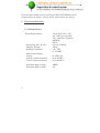
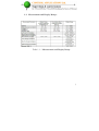
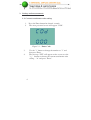
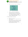
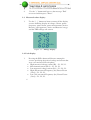
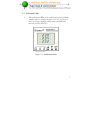
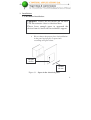
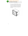
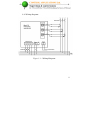
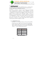
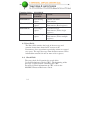
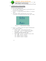
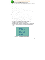
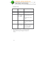
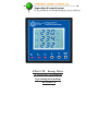
ElNet LTE Energy Meter
& Electrical Powermeter
Operating Instructions
Revision 1.4
Table of Contents
1.General specifications .................................................................. 2
1.1. Technical Data: ..................................................................... 2
1.2. Measurement and Display Range: ....................................... 3
2.Settings and measurements.......................................................... 4
2.1. Current transformer ratio setting: ...................................... 4
2.2. Voltage transformer ratio setting: ....................................... 5
2.3. Measured values display: ..................................................... 6
2.4. Peak display: ......................................................................... 6
2.5. Indication LEDs: ................................................................... 7
2.6. No volt & phase order alarm relay (option):....................... 8
3.Installations .................................................................................. 9
3.1. Mechanical installation: ....................................................... 9
3.2. Wiring diagram: ................................................................. 11
4.MODBUS Protocol: .................................................................... 12
4.1. MODBUS Framing ............................................................. 12
4.2. RTU Frame Format: ........................................................... 13
4.3. Address Field: ..................................................................... 13
4.4. Function Field: .................................................................... 13
4.5. Data Field: ........................................................................... 14
4.6. Check Field: ........................................................................ 14
4.7. Registers for Elnet LTE Powermeter: ............................... 15
4.8. Register addresses: ............................................................. 16
5.Communication Settings: ........................................................... 17
5.1. Communication Address: ................................................... 17
5.2. Baud Rate: ........................................................................... 17
5.3. Available Baud Rates for the ElNet LTE ........................... 17
Parity: .................................................................................. 17
6. Communication & Alarms Settings.......................................... 18
6.1. To set up Communication ................................................... 18
6.2. To set up Alarms: ................................................................ 19
Dear customer, thank you for selecting the Elnet LTE Multimeter for
measurements of voltage, current, power, power factor and energy.
1. General specifications
1.1. Technical Data:
Power Requirements
Dimensions (H x W x D)
Shipping Weight
Working Conditions
Measurement Range:
Voltage
Voltage (with transformer)
Current (with transformer)
Maximum Input Voltage
Maximum Input Current
2
: 110 or 230 VAC ± 10%
: 90 - 250 VAC (optional)
: 110 - 280 VDC (optional)
: 60/50 Hz
: 20VA
: 96 x 96 x 80 mm
: 450 gr.
: -20 – 70ºC
: 0 - 95 RH%
: 0 - 650 VAC
: up to 999 KV
: up to 999 KA
: 1000V
: 6A
1.2. Measurement and Display Range:
Table 1.1 – Measurement and Display Range
2. Settings and measurements
2.1. Current transformer ratio setting:
1.
2.
Press the Enter button for about 6 seconds.
The enter password screen will appear "COD".
Figure 2.1 – Enter Code
3.
4.
Use the " " button to change the number to "1" and
then press Enter.
The message "SET" will appear on the screen, use the
" " buttons to choose the current transformer ratio
setting – "A" and press "Enter".
5.
The current transformer setting screen will appear.
Figure 2.2 – Set Current Transformer
6.
7.
On the second line of the screen appears the
secondary value of the current transformer (5A).
On the third line appears the value of the primary
current transformer which you can change by using
the " " buttons, when finished press "Enter".
Use the " " button until the message "End" appears
on the screen and then press "Enter".
2.2. Voltage transformer ratio setting:
1.
2.
3.
Repeat steps 1.3.1 -1.3.3.
Use the " " button until "Set V" appears on the screen
and press "Enter".
On the second line of the screen appears the secondary
value of the voltage transformer (110V). On the third
line appears the value of the primary voltage
transformer which you can change by using the " "
buttons, when finished press "Enter".
4.
Use the " " button until you see the message "End"
on screen and then press "Enter".
2.3. Measured values display:
1.
Use the " " buttons to browse among all the display
screens including display of voltage, current, power,
frequency, power factor, power measurement (Active,
Reactive, and Apparent), Active and Reactive energy
and the THD voltage and current.
Figure 2.3 – Energy display
2.4. Peak display:
1.
Pressing the Hi/Lo button will browse among the
screens specifying the peak of voltage and current that
were ever measured for each phase:
High measured voltage current (Hi) – L1, L2, L3.
Max demand current (Hi.d) – L1, L2, L3.
Low measured voltage current (LO) – L1, L2, L3.
High (Hi) measured Frequency (hz), Power Factor
(Cos ) – L1, L2, L3.
Low (LO) measured Frequency (hz), Power Factor
(Cos ) – L1, L2, L3.
2.5. Indication LEDs:
1.
The indication LEDs easily enables the user to identify
whether there is voltage in phases L1, L2, L3. In case
there is voltage in phase connections, the LED will
turn on (at least 50 VAC).
Figure 2.4 – Indication Leds
2.6. No volt & phase order alarm relay (option):
1.
2.
When the voltage is proper (above 50VAC,
adjustable) and the phase order is proper, the alarm
relay will be closed, as it appears in the wiring
diagram. The maximum current possible to transfer
through this relay is 150ma, which is enough to
operate a regular control relay.
To set the minimum voltage value for the No Volt
alarm, and to enable / disable the alarms relay in case
of phase disorder please read paragraph 5.0 General
Setting.
3. Installations
3.1. Mechanical installation:
Comment: Please do not install the ELNET
LTE Powermeter close to electrical bars.
Please leave enough space to approach the
device from its back side for technical support.
Please choose the proper place for installation
in the panel and prepare a square hole
according to Figure below:
Height
90 mm
Width
90 mm
Figure 3.1 – Space in the electrical panel
Please insert the ELNET LTE Powermeter into
the suitable space prepared in advance. Make
sure you insert the device in the right direction.
The device is equipped with a plastic knob for
adjustment when installed in electrical panels.
The thickness of the panel door should be less
than 4mm.
3.2. Wiring diagram:
Figure 3.2 – Wiring Diagram
4. MODBUS Protocol:
The ElNet LTE Energy & Power Multimeter has a serial interface
port allowing direct interface with an external communication
network supporting the MODBUS Protocol.
MODBUS is an Industry Standard, widely known and commonly
used communications protocol. Using MODBUS provides
communication between a PC and up to 247 Powermeter slaves on
a common line - the PC being the master and the powermeters the
slaves. The PC initiates the transaction (either a query or
broadcast) and the Powermeter(s) responds. Powermeters respond
to the master PC’s request, but will not initiate any transmission
on its own. The PC sends a single Query transaction and the
Powermeter responds in a single response frame and is capable of
only one query and one response at a time.
4.1. MODBUS Framing
MODBUS uses the standard Remote Terminal Unit (RTU)
transmission mode. RTU mode sends data in 8-bit binary
with or without parity bit data format. For the ElNet LTE
Energy & Power Multimeter to successfully communicate,
choose “1” in the communication Set Up.
Field
No. of bits
Start bit
Data bits
Parity
Stop it
1
8
1
1
RTU Data Format
4.2. RTU Frame Format:
Query and response information is sent in frames.
Each frame contains: Address; Function; Data;
Check.
Address
Function
Data
Check
8 bits
8 bits
N * 8 bits
16 bits
RTU Message Frame Format
If the receiving device (Powermeter) detects a time laps of
five characters, it will assume the message is incomplete
and will flush the frame. The device then assumes that the
next byte received will be an address. The maximum query
and response message length is 256 bytes includuing check
characters.
4.3. Address Field:
Each Powermeter is designated in a network system by a
user assigned address. The Address can be any number
between 1 and 247. The Powermeter will only respond to
its own specifically assigned address.
4.4. Function Field:
The function field contains the code that tells the
Powermeter what action to perform.
The ElNet LTE uses and responds to four standard
Message Format Functions.
Function Codes : 03;04;06;16
Function
Meaning in
MODBUS
Function 03
Function 04
Function 06
Function 16
Read holding
register
Read input
register
Preset single
register
Preset multiple
register
Action
Obtain data from
Powermeter
Obtain data from
Powermeter (Read register)
Transmit data to
Powermeter (Write single
register)
Transmit data to
Powermeter (Write multiple
register)
4.5. Data Field:
The Data field contains the body of the message and
contains instructions from the PC master to the
Powermeter slave to perform a particular action or respond
to a query. The reply message from the Powermeter will be
information contained in one or more of its registers.
4.6. Check Field:
The error check field contains the result of the
Cyclical Redundancy Check (CRC). The beginning of the
message is ignored when calculating the CRC.
For more detailed information on CRC, refer to the
MODBUS Protocol Reference Guide.
4.7. Registers for Elnet LTE Powermeter:
The ElNet LTE is capable of supporting either the Function 03
or Function 04 Message Format. In a reply to a query from the
PC master for a reading from a particular field, the response
from the Powermeter can be either in Format 03 or Format 04
but will depend on the Format the query was originally sent in.
The difference is significant because when using Function 03,
the ElNet LTE will only send the INTERGER part of the field
value requested and the PC master will only display the
INTERGER part of the field value. On the other hand, Function
04 is capable of sending two separate halves of the full FLOAT
requested information (each half contained in a separate
register). Then it is the task of the PC master to merge the two
halves into a full FLOAT reply (For more detailed information
See IEEE Standard 754 Floating - Point).
E.G. 1: If the user’s PC master supports Function 03,
then the reply will contain the INTERGER part
of the field only.
The PC master requests the Voltage rom Line1,
and the actual Voltage in that field is 230.5 Volts.
Function 03 will respond with the INTERGER only
i.e.230V.
E.G. 2: If the user PC master supports Function 04, then the
reply will contain the information stored in the two
registers asssigned to that field and will contain the full
and accurate reply.
The PC master requests the Voltage from Line1, and the
actual Voltage in that field is 230.5 Volts.
Function 04 will respond with a composite reply of both
register 1 and 2 giving the full FLOAT value (in IEEE
Format) from that field i.e. 230.5V.
4.8. Register addresses:
The ElNet LTE MODBUS registers addresses are updated
from time to time and can be downloaded from the
following web site:
http://www.ddc.co.il/elnet-pdf/elnet_comm.pdf
5. Communication Settings:
In order to connect the ElNet LTE Energy & Power Multimeter
to a PC or other device, for successful communications, both
Communication Setup parameters must match; i.e. the PC port
and the configuration settings of the Power meter, Address,
Baud Rate, Parity must match.
5.1. Communication Address:
Each Power meter in a communication system must have its
own unique address. ElNet LTE works on MODBUS
protocol, so the available addresses are - from ‘1’ to ‘247’.
5.2. Baud Rate:
The Baud Rate is the communication speed in Bits per second
(BPS) for communication between ElNet LTE with the PC or
other device. The better the communication line quality, the
faster the communications may be (higher Baud Rate value).
If the communication line is routed through a “noisy”
environment, it may be necessary to decrease the Baud Rate.
5.3. Available Baud Rates for the ElNet LTE
are: 300; 600; 1200; 2400; 9600; 19200 bps.
5.4. Parity:
The parity can be defined as ODD, NONE or
EVEN.
6. Communication & Alarms Settings
6.1. To set up Communication
1. Press the "Enter" button for about 6 seconds until the insert
password screen will appear.
2. Use the " " to change the password (COD) to "2" and press
"Enter".
3. The message "SET" will blink on the screen. On the
second line, you will find the functions that require setting.
Figure 6.1 – Communications settings
4. Use the " " buttons to chose the required communication
feature and press "Enter":
Address "Adr" – can be changed by using " "
buttons from 1 to 255, when finished press "Enter".
Baud "bud" – use the " " buttons to choose
300,600,1200,2400,4800,9600,19200.
Parity "PAr" - use the " " buttons to choose from:
O81 - ODD, 8 data bit, 1 Stop bit.
E81 - EVEN, 8 data bit, 1 Stop bit.
n81 - NONE, 8 data bit, 1 Stop bit.
6.2. To set up Alarms:
1. Press the "Enter" button for about 6 seconds until
the insert password screen will appear.
2. Use the " " to change the password (COD) to "2" and press
"Enter".
3. The message "SET" will blink on the screen.
* The following will activate the "Alarms relay":
4.
In order to set the Low Voltage alarm - use the " "
buttons to scroll to "AL" and press "Enter".
5. The SET ALARM screen will appear - use the " " buttons
to define the Low Voltage level for activating the alarm
and press "Enter".
6. In order to set the Phase Order alarm - use the " "
buttons to scroll to Ord and press "Enter".
7. The Phase Order alarm will appear, use the " " buttons in
order to activate\deactivate the alarm (change from No to
Yes).
Figure 6.1 – Communications settings
Functions List:
Function
Value
Comments
Adr
Bud
0-247
300-19200
BPS
O = ODD
N = NONE
E = EVEN
Powermeter address
Setting the Baud rate
AL
0- 400 V
Minimum voltage to
activate the "No volt
relay".
Ord
YES = Yes
NO = NO
Setting the option to
activate the "No volt
relay" by the phase
disorder problem.
COP
8.
Parity setting
Data field is fixed = 8
bit
Start/Stop bit is fixed
= 1 bit
When finished use the " " buttons until the
"End" the message will appear and presses
"Enter".