1
MODEL 305 Manual
FLIGHT SYSTEMS
DESCRIPTION (Cont.)
VOLTAGE SENSE “J4-2 and 3”
When the engine starts, the generator supplies AC voltage to the voltage
regulator J4 pin 2 (L1), and J4 pin 3 (L0). The voltage regulator looks at
the amplitude of this AC voltage, and makes any necessary corrections
to the field current. During operation, applying or adding loads to the
generator decreases the voltage on the sensing terminals. The voltage
regulator will then increase the DC field current, thereby offsetting the
voltage drop. When loads are removed (decreasing load) the reverse is
true. Continuously adjusting the field current as load changes is how
voltage regulation is achieved.
VOLTAGE ADJUSTMENT “J4 Pins 1, 4 and 5”
J4- (1 and 4) are tied together internally in the voltage regulator and J4-5 is
connected to the internal return of the voltage regulator. For 60 Hz, an
external jumper is connected between J4-4 and J4-5; for 50 Hz a potentiometer is connected here. J4-1 is not used. (Refer to Generator Manual).
EXTERNAL CAPACITOR “J4-8 and 6”
The external capacitor on top of the original Onan voltage regulator
has been incorporated into the printed circuit board on F.S. Model
305. The two wires with Fast-On terminals that connected the
external capacitor (J4-8 and J4-6), are not connected to the Model
305 Regulator and should be taped. The function of this capacitor
is to filter the rectified voltage applied to J4-9.
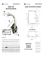
WIRE HARNESS
An eight inch long pigtail harness, from the voltage regulator to the
plug, is provided. The wire is automotive #18 AWG with SXL insulation designed to withstand vibration and high temperature. Each wire
is stamped J1-1 thru J1-12. The black wire is on J1-1.
4
MODEL 305 Manual
FLIGHT SYSTEMS
PRE-INSTALLATION MAINTENANCE
Important: It is necessary to perform certain maintenance
items prior to installing a new regulator. Failure to perform
this maintenance will void the warranty and may result in the
premature failure of the new regulator.
ENGINE
The engine must be in good running condition so that it can supply the
necessary horsepower to the generator under full load. The governor
must be set at so that the engine runs at the proper RPM (for 60 Hz,
4-pole, 1800 RPM; 2-pole, 3600 RPM). The governor must not be
surging, even at no load (slight surging is normal on cold start-up but
should go away after a minute or so). A dirty or gummed up carburetor will cause surging. The electric automatic choke must be operating
properly so that it does not stick or fail to open, thereby causing the
engine to run excessively rich. If any of these problems exist, they must
be corrected before installing the new regulator. Refer to the applicable
Onan service manual for your model for engine servicing details.
GENERATOR
Checking the rotor DC resistance is particularly important before installing a new regulator. This is your chance to find out if there is a problem
that possibly caused the last regulator to fail. Unplug regulator. Measure
the resistance between pins 9 and 10 on the connector that plugs into
the regulator. It should be between 23 and 28 ohms. A reading much
lower than 23 ohms indicates a partial short in the rotor. A reading much
higher than 28 ohms indicates a problem with the brushes, slip rings or
a bad connection. The most likely cause will be dirty or oxidized slip
rings so check them first and clean if necessary (See Slick Stick, Pg.
9). If the resistance is still high, check the brushes and connections.
If possible, check the stators for grounds (See G-MAN, pg. 9). Make
sure that the field flash voltage is reaching the regulator by measuring 12
VDC on pin 7 to frame ground during cranking. No voltage indicates a
control board or wiring problem.
5