1
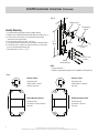
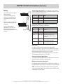
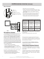
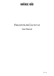
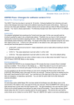
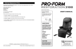
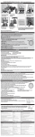
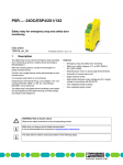
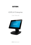
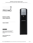
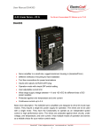
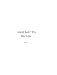
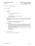
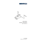
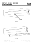
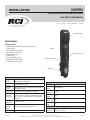
3525PRX
INSTALLATION
3525 Electromechanical Data Rack Handle
Lock with Proximity Reader
Proximity Reader
Specifications
Package Contents
•3525PRX Electromechanical Data Rack Handle Lock with Proximity Reader
•M3x25 Mounting Screws (qty 4)
•M3x14 Mounting Screw (qty 1)
•Rotation Limiter (qty 1)
•Cam Bolt (qty 1)
•Top Mounting Bracket (qty 1)
•Bottom Mounting Bracket (qty 1)
•Installation Instructions (qty 1)
Fig. 1
Tri-Color Status LED
Data Rack Handle
Lock Plug
Actuator Module
Supply
12VDC to 24VDC (NOTE: Status LED will blink red if the
Voltage
supply voltage is out of range.)
Standby
50mA maximum at 12VDC
Current
Operating
200mA maximum at 12VDC (with no external mechanical
Current
load applied to handle)
Stall Current 1A maximum at 12VDC (limited to 2 seconds)
1 second maximum (NOTE: Power must be present
Operating
during transit times. If power is removed while the lock
Transit Time slide is in transit, it will complete it’s cycle when power
is restored.)
Electronic
3 seconds minimum
Unlock Time
Open
Collector
Rated for supply voltage, maximum load
Outputs
Alarm Outputs 100mA/ output maximum
IS3525PRX
Proximity Reader Module
Voltage
12VDC to 24VDC
Operating
20mA maximum
Current
Transmit
125kHz
Frequency
DATA Signal
5VDC
Voltage
DATA Pulse
40µs
Interval Time
DATA Signal
2ms
Delay
3525PRX
Overall
8-1/4” H x 1-15/32” W x 2-1/8” D Dimensions (210 x 37 x 54.3mm)
© 2015 Rutherford Controls Int’l | A DORMA Group Company
www.rutherfordcontrols.com • Phone: 1.800.265.6630 • Fax: 1.800.482.9795 • E-mail: [email protected]
R03/15CA-2
YELLOW - 200 mA OUTPUT FOR ALARM
BROWN - 200 mA OUTPUT FOR ALARM
3525PRX Installation Instructions (Continued)
Fig. 2
1” *
25mm
Rotation Limiter
CAM
Handle Mounting
1.Assemble handle according to the proper handing required.
2.Rotation Limiter & Bottom Mounting bracket determine handing. (Fig. 3)
3.If existing cam or rod mechanism are installed on original handle
remove and install on new handle.
4.Ensure the proper cutout in the door. (See Fig. 2)
5.Install handle though cutout and install top & bottom mounting brackets.
6.Install wiring harness and route to hinge side of door securing in place
to ensure that nothing will bind or catch.
7.Proceed to wiring. (See Figs. 4, 5 & 6)
5.9” *
150mm
Top Mounting
Bracket
CAM Bolt
M3x14mm Screw
(1 place)
M3x25mm Screw
(4 places)
Bottom
Mounting Bracket
NOTE:
1.Cut-out dimensions.*
2.Handing is determined by rotation limiter and bottom mounting bracket.
VIEWED FROM BACKVIEWED FROM BACK
Fig. 3
VIEWED FROM BACKVIEWED FROM BACK
ROTATION
IS COUNTER CLOCKWISE
HANDLE ROTATION HANDLE
IS COUNTER
CLOCKWISE
ROTATION IS CLOCKWISE
HANDLE ROTATION HANDLE
IS CLOCKWISE
FROM FRONT
FROM FRONT
FROM FRONT
FROM FRONT
Rotation Limiter
Rotation Limiter
Viewed from back.
Handle rotation is counter
clockwise from front.
Viewed from back.
Handle rotation is clockwise
from front.
VIEWED FROM BACK
VIEWED FROM BACK
VIEWED FROM BACK
VIEWED FROM BACK
HANDLE ROTATION IS COUNTER
HANDLE
CLOCKWISE
ROTATION IS COUNTER CLOCKWISE
HANDLE ROTATION IS CLOCKWISE
HANDLE ROTATION IS CLOCKWISE
FROM FRONT
FROM FRONT
FROM FRONT
FROM FRONT
2
Bottom Mounting Bracket
Bottom Mounting Bracket
Viewed from back.
Key rotation is counter clockwise
from front.
Viewed from back.
Key rotation is clockwise from front.
VIEWED FROM BACKVIEWED FROM BACK
KEY ROTATION
IS COUNTER CLOCKWISE
KEY ROTATION IS COUNTER
CLOCKWISE
FROM FRONT
FROM FRONT
VIEWED FROM BACKVIEWED FROM BACK
KEY ROTATION IS CLOCKWISE
KEY ROTATION IS CLOCKWISE
FROM FRONT
FROM FRONT
© 2015 Rutherford Controls Int’l | A DORMA Group Company
www.rutherfordcontrols.com • Phone: 1.800.265.6630 • Fax: 1.800.482.9795 • E-mail: [email protected]
3525PRX Installation Instructions (Continued)
Wiring
The 3525PRX contains two separate
functional modules:
Positive Red
GND Black
DATA1 White
DATA0 Green
The proximity module reads the
contents of a compatible proximity
cards and converts it to Wiegand
format.
The actuator module controls and
monitors the locking function of the
swinghandle.
These two modules operate
independently of each other and
require connection to an access
control unit (not provided), to be fully
functional.
Positive Red
GND Black
Input Trigger
Electronic Lock Status
Mechanical Lock Status
Fig. 4
The proximity reader module of the swinghandle is accessed with a
four pin connector attached to a harness connected to the module’s circuit
board. The module’s connector pinout is:
Wire Color Description
Note
Black
GND
ground
Red
Positive
12 to 24VDC power supply input
Green
DATA0
DATA0 output
White
DATA1
DATA1 output
The actuator module of the swinghandle is accessed with a six pin
connector on the rear of the unit, shown below.
Wire Color
Description Note
Black
GND
ground
Red
Positive
12 to 24 VDC power supply input
Pin 3
N/C
no connect
Orange
Input Trigger
command input (9VDC up to
supply voltage, 100 milliseconds
minimum)
Brown
Electronic
Lock Status
open collector output (sink to
ground, 100mA max. load)
Blue
Mechanical
Lock Status
open collector output (sink to
ground, 100mA max. load)
Input Trigger
This signal is used to control the electronic lock slide position.
For UNLOCKED position: Supply 9VDC minimum (do not exceed supply
voltage) for at least 100 milliseconds. The lock will remain unlocked for as
long as the signal is present, or a minimum of 3 seconds. Signal timing can typically be adjusted through the access control device.
The input trigger current draw is less than 10mA.
Electronic Lock Status Output Signal
This output will provide a 100mA MAX sink to GND when the lock slide is
electromechanically moved to the unlocked position.
Mechanical Lock Status Output Signal
This output will provide a 100mA MAX sink to GND when the handle is in
the open position or when the keylock in the actuator is manually unlocked.
NOTE: These outputs are open collector outputs rated for input voltage
with a maximum load of 100mA. To avoid damage to the 3525PRX, do not
exceed voltage and current ratings.
© 2015 Rutherford Controls Int’l | A DORMA Group Company
www.rutherfordcontrols.com • Phone: 1.800.265.6630 • Fax: 1.800.482.9795 • E-mail: [email protected]
3
+
3525PRX Installation Instructions (Continued)
Wiring (Continued)
RED:
Postive
RED - 12/24
VDC POSITIVE
BLACK - 12/24 VDC NEGATIVE
BLACK: Negative
WHITE - ACTIVATION TRIGGER
YELLOW - 200 mA OUTPUT FOR ALARM
BROWN - 200 mA OUTPUT FOR ALARM
ORANGE: Activation Trigger
BLUE: 100mA Output for Alarm
BROWN: 100mA Output for Alarm
1.Red & Black are 12 to 24 VDC input voltage.
2.Orange is a positive input with a Normally Open Switch. The lock
will unlock for a minimum of 3 seconds on a momentary activation
(50 millisecond minimum) or remain unlocked as long as the
circuit is closed.
3.Blue is an alarm that will activate when the key is used to unlock
the cabinet or anytime the handle is not seated and locked.
4.Brown is an alarm that will activate when the lock is electrically
activated and will remain on until the lock electrically relocks.
Fig. 5
12~24 VDC
POWER SUPPLY
-
BLACK
RED
+
ORANGE
BLUE
100mA MAX
BROWN
100mA MAX
Fig. 6
FCC Compliance Statement
This equipment has been tested and found to comply with the limits
for a Class B digital device, pursuant to part 15 of the FCC rules.
These limits are designed to provide reasonable protection against
harmful interference in a residential installation. This equipment
generates, uses and can radiate radio frequency energy and, if not
installed and used in accordance with the instructions, may cause
harmful interference to radio communications. However, there is no
guarantee that interference will not occur in a particular installation. If
this equipment does cause harmful interference to radio or television
reception, which can be determined by turning the equipment off and
on, the user is encouraged to try to correct the interference by one or
more of the following measures:
•Reorient or relocate the receiving antenna.
•Increase the separation between the equipment & receiver.
•Connect the equipment into an outlet on a circuit different from
that to which the receiver is connected.
•Consult the dealer or an experienced radio/TV technician for help.
FCC Caution: This device complies with Part 15 of the FCC Rules.
Operation is subject to the following two conditions:
1.This device may not cause harmful interference and
2.This device must accept any interference received, including
interference that may cause undesired operation.
4
Lock Status
Latch LED
Alarm Wires
Secure
Steady Blue
Inactive
Electrically Released
Blue/ Magenta
Flashing
Brown Active
Mechanically
Released
Blue Flashing
Blue Active
Handle Not Fully
Closed
Blue/Red Flashing
Blue/Brown Active
Flashing Red
N/A
Supply Voltage out of spec
VIEWED FROM BACK
HANDLE ROTATION IS COUN
FROM FRONT
NOTE: The lock sensor is an optical device that senses the presence
of the locking cam. Reflectivity of the locking cam material can effect sensing.
VIEWED FROM BACK
KEY ROTATION IS COUNTER CLOCK
RF Exposure Warning: The equipment complies with RF exposure
FROM FRONT
limits set forth for an uncontrolled environment. The antenna(s) used
for this transmitter must not be co-located or operating in conjunction
with any other antenna or transmitter. You are cautioned that changes or modifications not expressly
approved by the party responsible for compliance could void your
authority to operate the equipment.
Industry Canada Compliance Statement
This digital apparatus does not exceed the Class B limits for radio
noise emissions from digital apparatus as set out in the interferencecausing equipment standard entitled “Digital Apparatus,” ICES-003 of
Industry Canada.
Cet appareil numérique respecte les limites de bruits radioélectriques
applicables aux appareils numériques de Classe B prescrites dans la
norme sur le material brouilleur: “Appareils Numériques,” NMB-003
édictée par l’Industrie.
© 2015 Rutherford Controls Int’l | A DORMA Group Company
www.rutherfordcontrols.com • Phone: 1.800.265.6630 • Fax: 1.800.482.9795 • E-mail: [email protected]