1
MacroNode I/O™
User Manual
Control & Information Technology Group
134 W Rio Robles Drive
San Jose, CA 95134
Main: 408.750.0300
Fax: 408.750.2990
Manual Rev. 10
03/2011
MacroNode I/O™ User Manual
Copyright
This manual and the software described in it are copyrighted with all
rights reserved. Under the copyright laws, this manual and software may
not be copied, in whole or part, without the prior written consent of MKS
Instruments. The same proprietary and copyright notices must be affixed
to any permitted copies as were affixed to the original. This exception
does not allow copies to be made for others whether or not sold, but all of
the materials purchased may be sold, given, or loaned to another person.
Under the law, copying includes translating into another language or
format.
© MKS Instruments - Controls Group, 2011
134 W Rio Robles Drive
San Jose, CA 95134
Preface
About this manual
This manual is designed to serve as a guideline for the installation, setup,
operation and basic maintenance of the MacroNode device. The
information contained within this manual, including product specifications,
is subject to change without notice. Please observe all safety precautions
and use appropriate procedures when handling the MacroNode product
and its related software.
Export Regulation
MKS Products provided subject to the US Export Regulations. Diversion
or transfer contrary to U.S. law is prohibited.
Page 2 of 44
© MKS Instruments CIT Products 2011, All rights reserved
MacroNode I/O™ User Manual
Table of Contents
General Information ......................................................................................................................................5
1.1
2
CONVENTIONS USED IN THIS USER MANUAL ......................................................................................5
Installation and Setup ............................................................................................................................6
2.1
SHIPPING BOX CONTENTS ................................................................................................................6
2.2
HARDWARE DESCRIPTION ................................................................................................................6
2.3
INSTALLATION ..................................................................................................................................7
2.4
POWER AND I/O W IRING ...................................................................................................................7
2.4.1
Power Supply Wiring .............................................................................................................7
2.4.2
I/O Mating Connector Information .........................................................................................8
2.4.3
Analog Expansion I/O Wiring .................................................................................................9
2.4.4
Digital Expansion I/O Wiring ............................................................................................... 10
2.4.5
Combo I/O Wiring ............................................................................................................... 11
2.5
DIGITAL INPUT INTERFACE EXAMPLE .............................................................................................. 12
2.6
DIGITAL OUTPUT INTERFACE EXAMPLE .......................................................................................... 12
2.7
ANALOG INPUTS ............................................................................................................................ 13
2.7.1
Configuring Analog Inputs .................................................................................................. 14
2.8
ANALOG OUTPUTS ........................................................................................................................ 15
2.9
DIAGNOSTIC SERIAL PORT ............................................................................................................ 15
2.10 ETHERNET CONNECTOR ................................................................................................................ 16
2.11 STATUS LED’S ............................................................................................................................. 16
2.12 ROTARY SWITCHES ....................................................................................................................... 16
2.13 I/O MONITORING ........................................................................................................................... 17
3
Quick-Start .......................................................................................................................................... 18
Network Configuration ............................................................................................................................... 24
3.1
3.2
CONNECTING TO A COMPUTER VIA TCP/IP ..................................................................................... 24
CONNECTING VIA A SERIAL TERMINAL SESSION .............................................................................. 25
TM
CONTROLweb
User Interface ................................................................................................................ 27
I/O MAPPING-MODBUS/TCP...................................................................................................................... 28
3.3
I/O MAPPING-ETHERNET IP ........................................................................................................... 31
3.3.1
Assembly Instance 100....................................................................................................... 33
3.3.2
Assembly Instance 101....................................................................................................... 34
3.3.3
Assembly Instance 102....................................................................................................... 35
3.3.4
Assembly Instance 103....................................................................................................... 36
4
TOOLweb™ Interface ......................................................................................................................... 37
4.1
TOOLWEB™ USER INTERFACE ..................................................................................................... 37
4.1.1
Control Access .................................................................................................................... 37
4.1.2
I/O Bindings ........................................................................................................................ 37
4.1.3
Data Collection Plans ......................................................................................................... 38
4.1.4
Data Collection Plan Editing ............................................................................................... 39
4.1.5
Charting Applet ................................................................................................................... 39
4.1.6
Download Data to Local PC ............................................................................................... 40
4.2
TOOLWEB™ TOOL SIDE INTERFACE ............................................................................................. 40
5
Specifications ...................................................................................................................................... 41
6
Model Code Description ..................................................................................................................... 43
Page 3 of 44
© MKS Instruments CIT Products 2011, All rights reserved
MacroNode I/O™ User Manual
WARRANTY .............................................................................................................................................. 44
Page 4 of 44
© MKS Instruments CIT Products 2011, All rights reserved
MacroNode I/O™ User Manual
General Information
The MacroNode I/O product line provides high density, compact and economical I/O solutions
for Ethernet Networks. The MacroNode supports up to 4 expansion slots of I/O which can be
ordered with any arrangement of digital, analog or combination cards. Both Modbus/TCP and
Ethernet/IP networks are supported. Additional data monitoring is available through a standard
web browser and the TOOLweb™ tool side Interface (XML over HTTP). The MacroNode
package provides DIN rail mounting and easy access to I/O through standard 37-pin D-Sub
connectors.
1.1 Conventions used in this User Manual
Warning
The WARNING sign denotes a hazard to personnel. It calls attention
to a procedure, practice, condition, or the like, which, if not correctly
performed or adhered to, could result in injury to personnel.
Caution
The CAUTION sign higlights information that is important to the safe
operation of the MacroNode, or to the integrity of your files. .
Note
The NOTE sign denotes important information. It calls attention to a
procedure, practice, condition, or the like, which is essential to highlight.
On screen buttons or menu items appear in bold and italics.
Example: Click OK to save the settings.
Keyboard keys appear in brackets.
Example: [ENTER] and [CTRL]
Pages with additional information about a specific topic are cross-referenced within the
text.
Example: (See page xxx)
Page 5 of 44
© MKS Instruments CIT Products 2011, All rights reserved
MacroNode I/O™ User Manual
2 Installation and Setup
This section describes the MacroNode hardware setup as well as the interface with the Ethernet
network. I/O connection examples are given in section 2.4.
2.1 Shipping Box Contents
•
•
2.2
MacroNode Product
Power mating connector
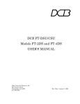
Hardware Description
LAN Interface
IP Address
Switches
Device Status
I/O Expansion
Figure 1 MacroNode Front Panel
Page 6 of 44
© MKS Instruments CIT Products 2011, All rights reserved
MacroNode I/O™ User Manual
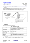
2.3 Installation
The MacroNode mounts on a standard 35mm DIN rail system. Make sure there is sufficient
side clearance for ventilation, to maintain an ambient operating temperature of 0°C to 50°C.
Figure 2 MacroNode DIN Rail Mounting
2.4 Power and I/O Wiring
The MacroNode requires three connections – one to the Ethernet network, one for device
power, and one for I/O signals. Ethernet and I/O cables are available from a variety of industrial
sources.
2.4.1
Power Supply Wiring
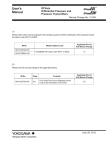
Connect an external 18-30 VDC power supply to the 3-terminal power connector. The
connector should be wired according to the labeling on the case.
Pin
1
2
3
Signal
18-30 VDC
Chassis GND
GND
Figure 3 Power Terminal Block
The manufacturer and ordering part number for the power terminal block connector is described
in the following table.
Table 1 Terminal Block Ordering Information
Description
MFG
Part Number
3-pin Terminal Block Weidmuller 1625620000
Page 7 of 44
© MKS Instruments CIT Products 2011, All rights reserved
MacroNode I/O™ User Manual
2.4.2 I/O Mating Connector Information
The following tables supply reference part numbers for mating I/O connectors. Table 2
describes a connector that uses terminal blocks and therefore appropriate for development.
Table 3 contains part numbers that are suitable for production purposes with solder cup
connections. Table 2 also contains the part number for a D-SUB hood that conforms to the 0.65
inch (1.65 cm) maximum height requirement.
Table 2 Development Mating I/O Connector
Description
37-pin D-SUB with Shell (Terminal Block)
MFG
Phoenix
Part Number
2300986
Table 3 Production Mating I/O Connector and Hood
Description
37-pin D-Sub Receptacle (solder cup)
37-pin D-Sub Metal Hood
Caution
Warning
MFG
Mouser
Mouser
Part Number
523-L77-DC37S
523-17E-1727-2
In order to guarantee proper operation and to prevent damage to
the product insure that the chassis ground is properly attached
for the application.
Follow all applicable electrical codes when mounting and
wiring any electrical device.
Page 8 of 44
© MKS Instruments CIT Products 2011, All rights reserved
MacroNode I/O™ User Manual
2.4.3 Analog Expansion I/O Wiring
+ 15V
+ 15V
AG ND
AG ND
A I8
AG ND
A I7
AG ND
A I6
AG ND
A I1
AG ND
A I2
AG ND
A I3
AG ND
A I4
AG ND
A I5
The MacroNode analog expansion board has two 37-pin D-Sub connectors used to access the
I/O points. Each I/O card type has unique pin assignments; the assignments for the analog
card are shown in the following figures.
1 2 3 4 5 6 7 8 9 10 11 12 13 14 15 16 17 18 19
-1 5V
-1 5V
AG ND
A I16
AG ND
A I15
AG ND
A I14
AG ND
A I9
AG ND
A I10
AG ND
A I11
AG ND
A I12
AG ND
A I13
20 21 22 23 24 25 26 27 28 29 30 31 32 33 34 35 36 37
Figure 4a Analog Inputs – Single-ended Mode
+ 15V
+ 15V
AG ND
AG ND
A I8+
AG ND
A I7+
AG ND
A I6+
AG ND
A I1+
AG ND
A I2+
AG ND
A I3+
AG ND
A I4+
AG ND
A I5+
Top Side Connector
1 2 3 4 5 6 7 8 9 10 11 12 13 14 15 16 17 18 19
-15V
-15V
AG ND
A I8-
AG ND
A I7-
AG ND
A I6-
AG ND
A I1AG ND
A I2AG ND
A I3AG ND
A I4AG ND
A I5-
20 21 22 23 24 25 26 27 28 29 30 31 32 33 34 35 36 37
Figure 4b Analog Inputs – Differential Mode
+15V
+15V
AG ND
AG ND
AO 8
AG ND
AO 7
AG ND
AO 6
AG ND
AO 1
AG ND
AO 2
AG ND
AO 3
AG ND
AO 4
AG ND
AO 5
Top Side Connector
1 2 3 4 5 6 7 8 9 10 11 12 13 14 15 16 17 18 19
-15V
-15V
NC
NC
NC
NC
NC
NC
NC
NC
NC
NC
NC
NC
NC
NC
NC
NC
20 21 22 23 24 25 26 27 28 29 30 31 32 33 34 35 36 37
Figure 5 Analog Outputs
Bottom Side Connector
Note
All Analog power comes from an internal power converter. External
pins for +/- 15 volts should be used as reference only. Supplies
have limited power and should not be used to drive external loads.
Page 9 of 44
© MKS Instruments CIT Products 2011, All rights reserved
MacroNode I/O™ User Manual
2.4.4 Digital Expansion I/O Wiring
19
SinkSel
SourceSel
37
RefSel
NC
17
24 GND
DIO 6
16
18
36
NC
35
NC
34
DIO 12
DIO 5
14
+24 IN
13
15
33
24 GND
32
DIO 11
24 GND
31
+24 IN
DIO 4
30
24 GND
12
29
DIO 10
11
+24 IN
28
+24 IN
10
24 GND
DIO 3
27
24 GND
9
26
8
+24 IN
24 GND
DIO 9
7
6
25
+24 IN
+24 IN
24 GND
DIO 2
24
24 GND
5
23
DIO 8
4
22
+24 IN
3
DIO 1
21
24 GND
1
2
20
DIO 7
+24 IN
The MacroNode digital expansion board has two 37-pin D-Sub connectors used to access the
I/O points. The +24V power must be supplied by an external source via these connectors. Each
I/O card type has unique pin assignments; the assignments for the digital card are shown in the
following figures. All “24 GND” labels are one net; they are not separate ground points.
Figure 6 Digital Top Side Connector
Table 4 Source/Sink Select for Digital Top Connector
Sink/Source Select
SinkSel
37
RefSel
19
SourceSel
NC
36
NC
18
35
NC
17
DIO 18
34
DIO 24
16
DIO 17
24 GND
15
33
24 GND
14
32
DIO 23
13
31
+24 IN
24 GND
DIO 16
30
24 GND
12
29
DIO 22
11
+24 IN
28
+24 IN
10
24 GND
DIO 15
27
24 GND
9
26
DIO 21
8
+24 IN
24 GND
25
+24 IN
7
24
24 GND
6
DIO 14
23
DIO 20
5
24 GND
+24 IN
4
22
+24 IN
3
DIO 13
21
24 GND
+24 IN
1
2
20
DIO 19
+24 IN
Short Pin 18 to 37
Short Pin 19 to 37
Sinking Input/Sourcing Output
Sourcing Input/Sinking Output
Figure 7 Digital Bottom Side Connector
Table 5 Source/Sink Select for Digital Bottom Connector
Sink/Source Select
Sinking Input/Sourcing Output
Sourcing Input/Sinking Output
Short Pin 18 to 37
Short Pin 19 to 37
Page 10 of 44
© MKS Instruments CIT Products 2011, All rights reserved
MacroNode I/O™ User Manual
2.4.5 Combo I/O Wiring
19
SinkSel
SourceSel
37
18
36
17
RefSel
NC
DIO 1
NC
35
34
16
NC
DIO 9
24 GND
15
33
+24 IN
32
DIO 2
14
DIO 8
+24 IN
24 GND
13
31
24 GND
DIO 7
30
DIO 3
12
29
+24 IN
11
+24 IN
24 GND
9
28
DIO 4
10
DIO 6
27
24 GND
+24 IN
24 GND
8
26
DIO 5
7
25
24 GND
24 GND
24
DIO 10
6
+24 IN
23
+24 IN
5
22
4
24 GND
+24 IN
DIO 11
3
21
24 GND
2
20
DIO 12
1
+24 IN
The Combo I/O Expansion Card has two 37-pin D-Sub connectors used to access the I/O
points. The +24V power must be supplied by an external source via these connectors. The
±15V power is supplied by an internal converter. The pin assignments are shown in the
following tables. All “24 GND” labels are one net; they are not separate ground points.
Figure 8 Combo Top Side Connector
Table 6 Digital Source/Sink Select for Combo Top Connector
Sink/Source Select
37
AO 1 +
19
AGND
AO 2 +
36
AO 1 -
18
AO 2 35
AGND
17
AGND
34
AI 1
16
AI 3
33
AI 5
15
AI 7
32
AI 2
14
31
AI 6
13
-15V
AI 8
12
30
+15 V
11
29
+15 V
-15V
24 IN
28
24 GND
9
27
SinkSel
10
RefSel
NC
26
SourceSel
8
25
NC
7
NC
24
24 GND
6
24 GND
23
DIO 16
5
DIO 14
4
22
+24 IN
+24 IN
21
DIO 15
3
24 GND
DIO 13
2
1
20
24 GND
AI 4
Short Pin 18 to 37
Short Pin 19 to 37
Sinking Input/Sourcing Output
Sourcing Input/Sinking Output
Figure 9 Combo – Diffrential Mode - Bottom Side Connector
Card Type
Analog Expansion Card
Combo Expansion Card
Number of Inputs
16/8
4
Type
Single-ended/differential
See Figures 4a and 4b in section 2.4.3 for wiring information.
Differential only
Single ended inputs must be connected in
pairs to create differential inputs. Particular
pairs must be used (input 1-5, 2-6, 3-7, 4-8).
Single-ended mode input is not supported on
combo card.
Page 11 of 44
© MKS Instruments CIT Products 2011, All rights reserved
MacroNode I/O™ User Manual
Table 7 Digital Source/Sink Select for Combo Bottom Connector
Sink/Source Select
Short Pin 18 to 37
Short Pin 19 to 37
Sinking Input/Sourcing Output
Sourcing Input/Sinking Output
Note
All Analog power comes from an internal power converter. External
pins for +/- 15 volts should be used as reference only. Supplies
have limited power and should not be used to drive external loads
2.5 Digital Input Interface Example
Digital I/O can be configured as either sinking or sourcing. Each input circuit includes an indicator
LED in series with the detection opto-coupler. The opto-coupler provides isolation between the
input and the processing circuitry. The inputs require 1.5 mA in order to turn on.
Vcc
V Ref
Vcc
LED X
V Ref
Digital Input point
LED X
Digital Input point
Vcc
Figure 10 Sourcing Input
Figure 11 Sinking Input
Below is an example of how to use the digital input interface for both the sinking and sourcing
hardware configurations. The digital I/O circuitry is powered from an external +24-volt power
source via the I/O connector.
24V GND
+24 V IN
DIO1
DIO1
Figure 12 Sourcing Input
Figure 13 Sinking Input
2.6 Digital Output Interface Example
The individual outputs will support up to a 200 mA load per channel. Each output is thermally
protected against short-circuiting (500 mA typically) and includes under voltage protection. The
output Fault State is accessible through software. External Schottky diodes are provided for output
transient protection and each I/O point is protected with a self-resetting poly fuse rated for 500 mA.
Page 12 of 44
© MKS Instruments CIT Products 2011, All rights reserved
MacroNode I/O™ User Manual
Outputs default to the OFF condition during power up and processor reset conditions. The figure
below shows the output circuitry.
+24V
Output
Driver
DIO X
24_GND
Figure 14 Digital Output
Below is an example of how to interface with the digital outputs for both the sinking and sourcing
hardware configurations. The digital I/O circuitry is again powered from an external +24-volt
power source via the I/O connector.
+24 V IN
+
24V GND
+
DIO1
DIO1
Figure 15 Sinking Output
Figure 16 Sourcing Output
2.7 Analog Inputs
The analog inputs are coupled directly to the processor. The processor is limited to 14-bits
analog to digital conversion. MacroNode SW allows analog conversion up to 16 bits, singleended or differential for easy implementation and compatibility. Resolution data is left-shifted if
resolution is set at 16-bits. The analog voltage span is fixed at –10V to +10V. See Section 3 for
configuration.
All analog circuitry is powered from an internal ±15 Vdc power source. The +15 V and -15 V
power is protected with a self-resetting poly fuse rated at 100 mA.
Table 8 Analog Voltage 2’s Complement Conversion Table for 12-bits A/D
Conversion Table
+10 V
0x07FF
5 mV
0x0001
0V
0x0000
-5 mV
0xFFFF
-10 V
0xF800
Page 13 of 44
© MKS Instruments CIT Products 2011, All rights reserved
MacroNode I/O™ User Manual
Table 9 Analog Voltage 2’s Complement Conversion Table for 14-bits A/D
Conversion Table
+10 V
0x1FFF
5V
0x0FFF
0.0012 V
0x0001
0V
0x0000
-0.0012 V
0xFFFF
-5 V
0x2FFF
-10 V
0x2000
Table 10 Analog Voltage Straight Binary Conversion Table for 14-bits A/D
Conversion Table
+10 V
0xFFFF
1V
0x8CCB
0.001 V 0x8003
0V
0x7FFF
-0.001 V 0x7FFC
-1 V
0x0CCC
-10 V
0x0000
Table 11 Number and Type of AI
Card Type
Analog Expansion Card
Combo Expansion Card
Number of Inputs
16/8
4
Type
Single-ended/differential
See Figures 4a and 4b in section 2.4.3 for wiring information.
Differential only
Single ended inputs must be connected in
pairs to create differential inputs. Particular
pairs must be used (input 1-5, 2-6, 3-7, 4-8).
Single-ended mode input is not supported on
combo card.
2.7.1 Configuring Analog Inputs
Analog inputs can be configured as single-ended, differential mode, up to 16-bit resolution,
straight binary or 2’s complement format. These are configured through the Webpage interface.
To configure these, unit has to be reset and the unit Webpage is refreshed within 30 second
after the unit boots.
Page 14 of 44
© MKS Instruments CIT Products 2011, All rights reserved
MacroNode I/O™ User Manual
2.8 Analog Outputs
The analog outputs are implemented using 12 bit D/A’s with a –10V to +10V output range.
MacroNode allows configuration up to 16-bits for compatibility. Data is left-shifted is resolution is
set higher than the HW resolution at 12-bit DAC. Analog outputs can also be configured as 2’s
complement or straight binary. The output drivers are capable of driving 2 KΩ (5 mA) output loads.
Analog outputs default to 0 volt during power up and processor reset conditions.
Table 12 Analog Voltage 2’s complement Conversion Table
Conversion Table
+10 V
0x07FF
5 mV
0x0001
0V
0x0000
-5 mV
0xFFFF
-10 V
0xF800
Table 13 Number and Type AO
Card Type
Analog Expansion Card
Number of Outputs
8
Type
Single-ended outputs
See Figure 5 in section 2.4.3 for wiring information.
Combo Expansion Card
2
Differential outputs
See Figure 9 in section 2.4.5 for wiring information.
2.9 Diagnostic Serial Port
The MacroNode has an RS-232 serial diagnostics interface available. The serial port will also
provide access to a proprietary command-line interface, with specific commands to display
advanced or detailed status information, and control of configuration parameters including those
available via the Web interface, and others that are intended for advanced or factory use, that
are not normally exposed via the Web interface.
The command-line interface supports the "help" command, which displays a brief synopsis of all
other supported commands, which should be self-explanatory to anyone sufficiently familiar with
the controller theory of operation, and the technologies involved (see section 3.2 for how to
connect the unit using serial COM port).
The diagnostics serial port is also used to display all legally required Copyright messages,
current version information and hardware configuration information during the unit's power-up
sequence.
Table 14 Diagnostic Serial Port Connector Pin-Out (DB-9 Female Connector)
Pin
2
3
5
RS232 Function
TXD
RXD
SGND
Page 15 of 44
© MKS Instruments CIT Products 2011, All rights reserved
MacroNode I/O™ User Manual
2.10 Ethernet Connector
The 100/10 BaseT Ethernet Port uses a standard shielded RJ45 connector or Fiber Optic
Channels. Indicators for the Ethernet Port are located on the front panel.
2.11 Status LED’s
The MacroNode has one LED that indicates the unit status and an additional LED that indicates
the network status. The function of these LED’s meets the requirements for each network
protocol. The following tables describe meaning of the various LED state for each protocol.
Table 10 Modbus/TCP Status LEDs
LED Color
Status LED
Network LED
Off
No power
No Power
Solid Red
Solid Amber
Not Supported
Booting
No Network Response (Disconnected)
Network Initializing, configuring DHCP
Alternating Red-Green
Watchdog failure, outputs off
Network Configuration Error
Alternating Red-Amber
I/O failure
Null network, IP address configuration Error
Alternating Green-Amber Not Supported
Not Supported
Blinking Amber
Unit Okay, Diagnostic Mode, Watchdog Inactive Standing by for Modbus master to connect
Blinking Green
Unit Okay, Production Mode, Watchdog Active Modbus master present and active
Table 11 Ethernet/IP Status LEDs
LED Color
OFF
Solid Green
Blinking Green
Blinking Red
Status LED
No Power
Device Operational
Not Supported
Minor Fault-recoverable
Network LED
No Power
Connected
No Connections
Connection Timeout
2.12 Rotary Switches
The Ethernet MacroNode has three rotary switches on the front panel, each switch representing
a decimal digit 0 through 9. These three switches serve two purposes:
1. Determines the least significant section of the IP address
2. Determines the operating mode
Table 12 Switch Conditions
Mode
Production
Production
Diagnostic
Diagnostic
Switch Settings
000
001-254
300
301-554
Watchdog
Enabled
Enabled
Disabled
Disabled
IP address
DHCP
192.168.0. (Switch Settings)
DHCP
192.168.0. (Switch Settings – 300)
Page 16 of 44
© MKS Instruments CIT Products 2011, All rights reserved
MacroNode I/O™ User Manual
When the unit is in normal (production) mode, the combinations of the rotary switches
represent a decimal number between 000 and 254. When the number is between 001 and 254,
this number is used to configure the last network segment of the static IP address, with a
factory set prefix 192.168.0.xxx, or any other prefix that may be configured through the
diagnostic serial port. If the rotary switch combination is set to 000, the unit will obtain an IP
address automatically using DHCP protocol.
To set the operating mode to diagnostics mode set the rotary switches to 300 or above. In
Diagnostic mode the watchdog is disabled, and the user is allowed to change the value of the
outputs via the Web-based diagnostic pages. Setting the switches to a value of 300 configures
the IP address using DHCP, and setting the switches above 300 configures the unit to a static
IP address.
For example: A switch setting of 330 means that the diagnostic mode is set, and the IP address
is statically configured to 192.168.0.30.
Note
Rotary switches decimal representation above 554 are reserved and
should not be used.
2.13 I/O Monitoring
There are multiple control and data monitoring interfaces for the unit:
• Modbus/TCP or Ethernet/IP control
• Web browser, manual control
• Web browser, configuration and graphical data monitoring
• XML streaming data acquisition, using TOOLweb™ protocol
Page 17 of 44
© MKS Instruments CIT Products 2011, All rights reserved
MacroNode I/O™ User Manual
3 Quick-Start
•
Set the IP address switches on the front of the unit to 3 1 0. The unit is now in Diagnostic
mode with a static IP address. The units IP address will be 192.168.0.10. Power the
MacroNode by supplying +24 volts to the 3-position terminal block power connector.
•
Power the I/O modules by supplying +24V for Digital modules via the I/O connector.
Note Analog +/-15 volts for Analog modules is supplied internally.
•
Attach a network cross-over cable between the unit and your PC or use a HUB to build a
small network.
•
Modify your PC network TCP/IP settings using the computer’s Connection Properties
menu to match the following:
PC IP Address:
PC Netmask:
192.168.0.1
255.255.255.0
Page 18 of 44
© MKS Instruments CIT Products 2011, All rights reserved
MacroNode I/O™ User Manual
•
Open a web browser window and enter http://192.168.0.10 in the address line. There is
a slight delay as the unit transfers content to your local browser. The main Device page
is displayed. If you are unable to load the page, check the units switch settings and
ensure the IP address of the PC is 192.168.0.1. Also check the Ethernet cable
connections to your PC and to the MacroNode.
Figure 17 Device ControlWeb page
Page 19 of 44
© MKS Instruments CIT Products 2011, All rights reserved
MacroNode I/O™ User Manual
•
To access configuration mode, reset the unit and refresh the above page within 30
seconds after the unit boots.
Figure 18 Device Configuration Webpage
Page 20 of 44
© MKS Instruments CIT Products 2011, All rights reserved
MacroNode I/O™ User Manual
•
Click on the Config I/O for the block to open the configuration page for the card. The
digital IO card debounce setting for all the digital IO point for the card is currently not
implemented. Please refer to cLogic documentation for software work-around.
Figure 19 Device Digital Card Configuration Webpage
•
The analog configuration is fixed for Ethernet/IP protocol except for analog input for
single-ended or differential. Modbus/TCP protocol allows protocol resolution, data
representation and type configuration as shown below:
Figure 20 Configurable analog parameters for Modbus/TCP protocol
Page 21 of 44
© MKS Instruments CIT Products 2011, All rights reserved
MacroNode I/O™ User Manual
•
The Device page provides current status on the unit and provides basic I/O control and
monitoring when the device is in diagnostic mode. Once in production mode, the
outputs can no longer be controlled via the webpage.
•
Selecting the underlined items in the I/O blocks chart will launch secondary I/O pages.
The following figures show the digital and analog input statuses that are displayed after
an underlined link is selected.
Figure 21 Digital and Analog Input WebPages
Page 22 of 44
© MKS Instruments CIT Products 2011, All rights reserved
MacroNode I/O™ User Manual
•
The digital and analog output WebPages provide basic control of the output points if the
unit is in diagnostics mode. The pull down menu allows the user to select the digital
output state or to enter in a value for an analog output. There is also a Blinking Output
pull down menu that allows the user to put an output into a blinking or oscillating state.
Figure 22 Digital and Analog Output WebPages
•
Click on the link for the analog or digital output page. Change the state of one of the
outputs by selecting an option from the pull down menu and for the case of analog enter
a number within the range of –10V to +10V.
If the output does not come on, check the status and network LEDs on the front of the unit. The
module LED should be blinking amber and the network LED should be blinking green. If the
states are different, reference the LED status table in section 2.10. Also, check all power
connections.
Page 23 of 44
© MKS Instruments CIT Products 2011, All rights reserved
MacroNode I/O™ User Manual
Network Configuration
The MacroNode network settings configure the 10/100 BaseT Ethernet port. The following are
factory-default Ethernet settings.
Parameter
IP-Address
Subnet mask
Default Gateway
Note
Setting
192.168.0.X
255.255.255.0
None
Reading or changing the network settings of an unknown unit is achieved by
connecting via a serial terminal session.
3.1 Connecting to a computer via TCP/IP
The Ethernet MacroNode is configured and controlled via its Ethernet port. The following steps
show how to configure a Windows PC for first-time communication with a unit.
1) Connect the unit to your PC by using an Ethernet crossover cable for direct point-to-point
connection, or connect through an Ethernet switch or hub.
Note
Some 10/100MB Ethernet interfaces may not detect the MacroNode™ when
using an Ethernet crossover cable. If you experience problems, connect through
an Ethernet switch or hub.
2) Change IP switches on the MacroNode to 3 1 0.
3) Change your PC network TCP/IP settings so that PC resides on same sub network as the
MacroNode I/O™.
Use the following TCP/IP settings:
IP Address:
Subnet Mask:
Default Gateway:
192.168.0.1
255.255.255.0
none
4) Open your PC web browser (Netscape, Internet Explorer, or equivalent).
Enter the IP address in the web browser’s address line.
http://192.168.0.10
The main page for the MacroNode will open.
Page 24 of 44
© MKS Instruments CIT Products 2011, All rights reserved
MacroNode I/O™ User Manual
3.2 Connecting via a Serial Terminal Session
Connect your computer to the diagnostics port (DB9) using a standard straight thru cable.
Using a terminal program such as Microsoft® HyperTerminal or Tera Term Pro you can now
communicate via the diagnostics port of the unit. The serial connection parameters are listed in
the following table.
Table 13 Serial Connection Parameters
Parameter
Baudrate
Data bits
Parity
Stop bits
Flow Control
Value
38400
8
None
1
None
Once connected the IP-Address can be changed by typing the menu command and pressing m
within 3 seconds: The current the IP address of the unit can be view by just typing menu.
Figure 23 Serial Diagnostics Menu Command
Page 25 of 44
© MKS Instruments CIT Products 2011, All rights reserved
MacroNode I/O™ User Manual
The modbus Throttle => Back2Back Limit is the number of back-to-back modbus commands
threshold before modbus request is changed to lower priority to allow other processes time to
run.
Modbus Throttle => Min Task Pri: should be set at 11.
The serial interface provides diagnostics for the device. The help command can be used to
display all commands available through the serial interface.
Figure 24 Serial Diagnostics Help Command
Page 26 of 44
© MKS Instruments CIT Products 2011, All rights reserved
MacroNode I/O™ User Manual
CONTROLwebTM User Interface
The user interface is web based. You can access it by simply browsing to the IP-address of the
CONTROLweb™ node.
Note
Microsoft Internet Explorer versions older than 5.5 may not function as expected
due to limitations of the browser.
The main page of the CONTROLweb™ unit shows a top view of the module. This is
referenced as the Device tab near the top of the page.
Figure 25 Device Homepage
Dynamic diagnostic details available from this page are:
• Unit data- model number, serial number, and software version
• Operational Mode
• Operation statistics
• Ethernet load
• Fieldbus Protocol
• Unit MAC address
Page 27 of 44
© MKS Instruments CIT Products 2011, All rights reserved
MacroNode I/O™ User Manual
By selecting an I/O of interest from the main page, a pop-up will appear for each section of I/O.
• Inputs can be read. (dynamic)
• Outputs can be set manually if the unit is in diagnostics mode
Note
The I/O is arranged in blocks, which represent expansion modules. The
last block is always a virtual I/O block which can be used in conjunction
with the cLogic feature. Please contact MKS for the cLogic API document
for more information on implementing the virtual I/O.
I/O Mapping-Modbus/TCP
The unit Modbus Slave ID is fixed at 255.
The Modbus mapping details can be viewed through the web browser interface by clicking on
the I/O Mapping Tab from the main page. The figure below is one example of what will appear
on the screen. The mapping will change depending on which I/O expansion modules are
installed and whether IO mapping is in block or contguous. The last block is not a physical
expansion module; it consists of virtual I/O only.
Page 28 of 44
© MKS Instruments CIT Products 2011, All rights reserved
MacroNode I/O™ User Manual
Figure 26 Modbus Data Mapping for unit with 2 expansion modules
Page 29 of 44
© MKS Instruments CIT Products 2011, All rights reserved
MacroNode I/O™ User Manual
The MacroNode IO supports the following MODBUS Functions:
1. ReadDiscreteInputs. As defined in the MODBUS Application Protocol Specification,
the device shall support reading one or more discrete inputs via the ReadDiscreteInputs
function.
2. ReadCoils. For the purposes of this device, a coil shall be synonymous with a Discrete
Output. As defined in the MODBUS Application Protocol Specification, the device shall
support reading one or more coils (discrete outputs) via the ReadCoils function.
3. WriteSingleCoil.
4. WriteMultipleCoils.
5. ReadHoldingRegisters. As defined in the MODBUS Application Protocol Specification,
the device shall support reading one or more registers via the ReadHoldingRegisters
function.
6. WriteSingleRegister. Is defined to access the HoldingRegisters.
When accessing an IO point, the following method is used.
DI address = Reference of DI Number – 1
For example for DI number = 4 with a reference of 4, the DI address would be 3.
Map this data in your Modbus/TCP scanner.
Note
For more details on Modbus, see http://www.modbus.org.
WATCHDOG TIMER
The Modbus/TCP Interface includes a watchdog timer to monitor and react in the event that
communications are not maintained between the client and the server within a programmable
amount of time. If communications exceed the timeout value (programmed into the Watchdog
Timeout Value Holding Register) a timeout will occur and the Watchdog Timeout Counter
register will increment 1 count for every timeout event that occurs. In the event that a timeout
occurs the Status LED will alternate between red-amber and green. Once a timeout occurs all
outputs are disabled.
The Watchdog Timeout value can be set from 100ms to 65535ms and can be disabled by
writing a value of 0 to the register. The Watchdog Timeout Counter increments on each timeout
event and is cleared by writing any value to the register.
Note
To ensure that the Watchdog Counter register is cleared the register should be
written to during initialization.
Page 30 of 44
© MKS Instruments CIT Products 2011, All rights reserved
MacroNode I/O™ User Manual
3.3 I/O Mapping-Ethernet IP
The Ethernet/IP I/O details can be viewed through the web browser interface by clicking on the
I/O Mapping Tab from the main page. The figure below is one example of what will appear on
the screen. The mapping will change depending on which I/O expansion modules are installed.
This page provides information for Instances 100 – 103. The table is broken down by byte
number as well as by the bits within said bytes. The byte total is displayed at the bottom of the
table. To change the instance, use the Assembly Instance drop down menu at the top of the
screen. Instances 100 and 101 do not include the virtual I/O where as instances 102 and 103
do.
Note
The I/O is arranged in blocks, which represent expansion modules. The
last block is always a virtual I/O block which can be used in conjunction
with the cLogic feature. Please contact MKS for the cLogic API document
for more information on implementing the virtual I/O.
Figure 27 Ethernet IP I/O Mapping
Page 31 of 44
© MKS Instruments CIT Products 2011, All rights reserved
MacroNode I/O™ User Manual
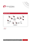
Below is an example of one way the expansion slots can be populated and the following
sections explains the resulting input and output bytes for this configuration. Note this is only one
example of how the expansion slots can be populated. The byte order conforms to the following
rules:
Expansion Slot 3
Expansion Slot 2
Expansion Slot 1
Expansion Slot 0
Digital control bytes for each slot always come before the analog control bytes.
Analog falls on even byte boundaries, a null byte is used for stuffing.
Analog is always low byte first then high byte.
Virtual I/O is after physical I/O
CPU Slot
•
•
•
•
{
{
{
{
{
MacroNode I/0TM
DIDO
LINK
100M
1
Combo
AIAO
2
1
2
Tx
LA N
Rx
0
100
8
2
6
IP
8
ADD. 10
6
16
15
4
0
2
4
0
1 8
2
6
4
MOD
NET
23
STAT 24V
24
STAT 15V
STAT 24V
mks
Figure 28 MacroNode with Digital, Analog, and Combo Expansion cards
Page 32 of 44
© MKS Instruments CIT Products 2011, All rights reserved
MacroNode I/O™ User Manual
3.3.1 Assembly Instance 100
Below is an example of Instance 100, which describes the information provided by the unit
(input values). This example demonstrates the fact that digital bytes always appear before
analog bytes. Also notice that byte number five is a stuff byte that forces the least significant
analog bytes to fall on an even byte boundary. The last line displays the total number of bytes
this unit produces.
Digital Inputs
Stuff Byte
Analog Inputs
Figure 29 Instance 100-Input Mapping
Page 33 of 44
© MKS Instruments CIT Products 2011, All rights reserved
MacroNode I/O™ User Manual
3.3.2 Assembly Instance 101
Below is an example of Instance 101, which describes the information, provided to the unit
(Outputs). This example demonstrates the fact that digital bytes always appear before analog
bytes. Also notice that byte number five is a stuff byte that forces the least significant analog
bytes to fall on an even byte boundary. The last line displays the total number of bytes this unit
consumes.
Digital outputs
Stuff Byte
Analog outputs
Figure 30 Instance 101-Output Mapping
Page 34 of 44
© MKS Instruments CIT Products 2011, All rights reserved
MacroNode I/O™ User Manual
3.3.3 Assembly Instance 102
Below is an example of Instance 102, which describes the information provided by the unit
(input values) plus the virtual inputs. This example demonstrates the fact that digital bytes
always appear before analog bytes and physical I/O appears before virtual I/O. Also notice that
byte number nine is a stuff byte that forces the least significant analog bytes to fall on an even
byte boundary. The last line displays the total number of bytes this unit produces including the
virtual inputs.
Physical Digital Inputs
Virtual Digital Inputs
Stuff Byte
Physical Analog Inputs
Virtual Analog Inputs
Figure 31 Instance 102-Input Mapping with Virtual I/O
Page 35 of 44
© MKS Instruments CIT Products 2011, All rights reserved
MacroNode I/O™ User Manual
3.3.4 Assembly Instance 103
Below is an example of Instance 103, which describes the information provided to the unit
(Outputs) including the virtual outputs. This example demonstrates the fact that digital bytes
always appear before analog bytes and that physical I/O appears before virtual I/O. Also notice
that byte number nine is a stuff byte that forces the least significant analog bytes to fall on an
even byte boundary. The last line displays the total number of bytes this unit consumes
including the virtual outputs.
Physical Digital Outputs
Virtual Digital Outputs
Stuff Byte
Physical Analog Outputs
Virtual Analog Outputs
Figure 32 Instance 103- Output Mapping with Virtual I/O
Page 36 of 44
© MKS Instruments CIT Products 2011, All rights reserved
MacroNode I/O™ User Manual
4 TOOLweb™ Interface
TOOLweb™ is a system-wide program for enabling and gathering real time data from multiple
elements of a process, and providing this data to factory based modules for analysis, FDC and
APC.
The Ethernet MacroNode uses TOOLweb™ functionality for the following:
•
•
Web based tools for data analysis and debug, directly from the I/O module
Real time data acquisition, using XML over HTTP
4.1 TOOLweb™ User Interface
TOOLweb™ functions are accessed and configured through the web browser interface. Users
must determine the I/O points of interest, those usually referred to as Key Process Variables.
Once these variables are named and scaled, they are available for data collection and analysis.
4.1.1
Control Access
Create the allowed permissions to process data.
Figure 33 Access Control
4.1.2
I/O Bindings
Select the I/O points to be available for TOOLweb™ functions. Each point is selected, given a
description, and scaled to meaningful process units. Up to 64 variables can be configured.
Page 37 of 44
© MKS Instruments CIT Products 2011, All rights reserved
MacroNode I/O™ User Manual
Figure 34 Collection Variables
4.1.3
Data Collection Plans
A data collection plan selects the process variables of interest, and the frequency of data
collection. Each collection plan can then be viewed using a Charting Applet, or can be
downloaded in CSV format to your local PC.
Figure 35 Collection Plan
Page 38 of 44
© MKS Instruments CIT Products 2011, All rights reserved
MacroNode I/O™ User Manual
4.1.4
Data Collection Plan Editing
Create a collection plan, and select the key process variables of interest:
Figure 36 Edit Collection Plan
4.1.5
Charting Applet
Once a data collection plan is configured, you can view the data using a built-in charting applet.
Figure 37 Charting Applet
Page 39 of 44
© MKS Instruments CIT Products 2011, All rights reserved
MacroNode I/O™ User Manual
4.1.6
Download Data to Local PC
Collection plan data can also be downloaded in CSV format:
Figure 38 Collection Plan Data
4.2 TOOLweb™ Tool Side Interface
The tool side interface is relevant when a MacroNode is connected to a BlueBox™ in a
semiconductor process tool APC, and e-diagnostic system.
The following messages are supported via the TOOLwebTM tool side Interface:
Message
CapabilitiesRequest/Response
Polling
Tracing
Bulktrace
Events
ControlParameter
SetRequest/Response
Supported
Yes
Yes
Yes
No
No
Yes
No
The names and units as exposed in the CapabilitesResponse are the same as defined in the
channel configuration. Reference the BlueBox™ Manual for additional details on interfacing with
BlueBox™.
Note
Microsoft Internet Explorer 5.0.1 or higher is required. Microsoft Internet Explorer
versions less than 5.5 may not function as expected due to limitations of the
browser.
Page 40 of 44
© MKS Instruments CIT Products 2011, All rights reserved
MacroNode I/O™ User Manual
5 Specifications
Physical Specifications
Criteria
Dimensions
I/O Connector
Ethernet Connector
RS-232 Connector
Weight
Specifications
4” H x 4” W x 1.5”D plus 0.7” per I/O slot
37-pin male D-sub
10/100 BaseT auto-switched, RJ45 with EMI filter, LED
indicators OR Fiber optic connector
TXD, RXD; DB9 connector
600g (1.32 lb)
Environmental Specifications
Criteria
Operating Temperature
Storage
Humidity
Specifications
0 to +55°C
-40 to +85 °C
5 to 95% non-condensing
Functional Specifications
Criteria
BUS Interface
Front Panel Indicators
Rotary Switches
Specifications
Ethernet – Modbus/TCP or Ethernet/IP
Network Status, Module Status, LINK, 100MB
IP address, operating mode
Power Specifications
Criteria
Input
Isolation
Specifications
Powered from I/O connector
+24VDC@120 mA min
DC/DC Isolation
Power Specifications
Criteria
Input
Isolation
Over Current Protection
Each Channel
Total
Specifications
Powered from I/O connector
+24VDC@120 mA min
DC/DC Isolation, 2.5KVrms
1.5A
3.0A
Input/Output Specifications per Card
Criteria
Specifications
DIDO Card
Number of Digital I/O
24 points (input or output)
Response Time
50µsec
Digital Input
Sink
Current sinking
Max -2.18 mA at Vin=0V
Logic Low Voltage
Min 4.1V to Max 30V
Logic High Voltage
Min 0V to Max 3.6V
Source
Current sourcing
Max 2.33 mA at Vin=24V
Input Low Voltage
Min 0V to Max 6V
Page 41 of 44
© MKS Instruments CIT Products 2011, All rights reserved
MacroNode I/O™ User Manual
Input High Voltage
Digital Output
Min 6.5V to Max 30V
Sink
Current sinking
Output OFF Voltage
200 mA max / channel
Min 23.8V @ 580uA @ RL=240Ω
Min 23.8V @ 1mA @ RL=120Ω
Output ON Voltage
Max 240mV @ 200mA @ RL=120Ω
Max 133mV @ 100mA @ RL=240Ω
Source
Current sourcing
Current max
Output ON Voltage
Output OFF Voltage
AIAO Card
Analog Accuracy
Analog Response Time
Analog Input
200 mA max / channel
750 mA per 6 DO
Min 23.3V @ 100mA @ RL=240Ω
Min 23.1V @ 200mA @ RL=120Ω
Max 0V @ 0uA @ RL=120Ω
Max 0V @ 0mA @ RL=240Ω
0.1% Full scale (-10V to 10V)
200 µsec
16 single-ended points or 8 differential points (s/w
selectable)
14 bit
1Khz RC filter
Analog Output
8 single-ended points
12 bit
Range (–10 to +10V)
5mA / channel into a 2 KΩ load
COMBO Card
Number of Digital I/O
Response Time
Digital Input
Current sinking
Current sourcing
Digital Output
Current sinking
Current sourcing
Current max
Analog Accuracy
Analog Response Time
Analog Input
Analog Output
16 points (input or output)
50 µsec
1.5 mA min,
1.5 mA min,
200 mA max / channel
200 mA max / channel
750 mA per 6 DO
0.1% Full scale (-10V to 10V)
200 µsec
4 differential points (s/w selectable)
14 bit
1khz RC filter
2 differential points
12 bit
Range (–10 to +10V)
5mA / channel into a 2 KΩ load
Page 42 of 44
© MKS Instruments CIT Products 2011, All rights reserved
MacroNode I/O™ User Manual
6 Model Code Description
The Model code of MacroNode defines the features of the Unit for Hardware, software and other
options:
BASE
Format:
MNOD
OPTIONS
-
E
FE
SLOT 1
-
DIDO
AIAO
AI
AIC
COMB
SLOT 2
-
DIDO
AIAO
AI
AIC
COMB
SLOT 3
-
Options
-E
-FE
Ethernet, RJ45
Ethernet, Fiberoptic
Slot Designations
-DIDO
-AIAO
-AI
-AIC
-COMB
24 Channel Digital I/O Card
16 Channel Analog In, 8 Channel Analog Out
16 Analog Inputs (Voltage Type Inputs)
8 Analog Inputs (Current Type Inputs)
Combination: 16DIDO, 4AI-DIF, 2AO-DIF
DIDO
AIAO
AI
AIC
COMB
SLOT 4
-
DIDO
AIAO
AI
AIC
COMB
Page 43 of 44
© MKS Instruments CIT Products 2011, All rights reserved
MacroNode I/O™ User Manual
WARRANTY
MKS Instruments, Inc. (MKS) warrants that for one year from the date of shipment the
equipment described above (the “equipment”) manufactured by MKS shall be free from defects
in materials and workmanship and will correctly perform all date-related operations, including
without limitation accepting data entry, sequencing, sorting, comparing, and reporting,
regardless of the date the operation is performed or the date involved in the operation, provided
that, if the equipment exchanges data or is otherwise used with equipment, software, or other
products of others, such products of others themselves correctly perform all date-related
operations and store and transmit dates and date-related data in a format compatible with MKS
equipment. THIS WARRANTY IS MKS’ SOLE WARRANTY CONCERNING DATE-RELATED
OPERATIONS.
For the period commencing with the date of shipment of this equipment and ending one year
later, MKS will, at its option, either repair or replace any part which is defective in materials or
workmanship or with respect to the date-related operations warranty without charge to the
purchaser. The foregoing shall constitute the exclusive and sole remedy of the purchaser for
any breach by MKS of this warranty.
The purchaser, before returning any equipment covered by this warranty, which is asserted to
be defective by the purchaser, shall make specific written arrangements with respect to the
responsibility for shipping the equipment and handling any other incidental charges with the
MKS sales representative or distributor from which the equipment was purchased or, in the
case of a direct purchase from MKS, with the MKS-CIT home office in San Jose, CA
This warranty does not apply to any equipment, which has not been installed and used in
accordance with the specifications recommended by MKS for the proper and normal use of the
equipment. MKS shall not be liable under any circumstances for indirect, special, consequential,
or incidental damages in connection with, or arising out of, the sale, performance, or use of the
equipment covered by this warranty.
THIS WARRANTY IS IN LIEU OF ALL OTHER RELEVANT WARRANTIES, EXPRESSED OR
IMPLIED, INCLUDING THE IMPLIED WARRANTY OF MERCHANTABILITY AND THE
IMPLIED WARRANTY OF FITNESS FOR A PARTICULAR PURPOSE, AND ANY WARRANTY
AGAINST INFRINGEMENT OF ANY PATENT.
Page 44 of 44
© MKS Instruments CIT Products 2011, All rights reserved