1
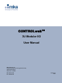
CONTROLwebTM
3U Modular I/O
User Manual
MKS Instruments, Inc.
Control & Information Technology Products Group
3350 Scott Blvd Bldg 4
Santa Clara CA 95054
Main: 408.235.7620
Fax: 408.235.7625
Revision 03
02/05
CONTROLwebTM User Manual
Copyright
This manual and the software described in it are copyrighted with all rights
reserved. Under the copyright laws, this manual and software may not be copied,
in whole or part, without the prior written consent of MKS Instruments. The same
proprietary and copyright notices must be affixed to any permitted copies as were
affixed to the original. This exception does not allow copies to be made for others
whether or not sold, but all of the materials purchased may be sold, given, or
loaned to another person. Under the law, copying includes translating into another
language or format.
© MKS Instruments - CIT Products Group, 2003
3350 Scott Blvd Bldg 4
Santa Clara, CA 95054
Preface
About this manual
This manual is designed to serve as a guideline for the installation, set up,
operation and basic maintenance of the CONTROLwebTM Remote I/O Unit. The
information contained within this manual, including product specifications, is
subject to change without notice. Please observe all safety precautions and use
appropriate procedures when handling this product and its related software.
2 of 32
© MKS Instruments CIT Products 2004, All rights reserved
CONTROLwebTM User Manual
Table of Contents
1
GENERAL INFORMATION ..................................................................................................................................4
1.1
1.2
2
THEORY OF OPERATION ............................................................................................................................................... 5
CONTROLWEB 3U ARCHITECTURE ........................................................................................................................... 6
INSTALLATION & SETUP ...................................................................................................................................8
2.1
CONTROLWEB INTERFACE DESCRIPTION ................................................................................................................. 8
2.2
MECHANICAL INSTALLATION ......................................................................................................................................... 9
2.3
ELECTRICAL INSTALLATION ........................................................................................................................................ 10
2.3.1 Power Wiring ........................................................................................................................................................ 10
2.3.2 I/O Wiring .............................................................................................................................................................. 10
2.3.3 Com Port Configuration ...................................................................................................................................... 13
2.3.4 Ethernet Connector ............................................................................................................................................. 13
2.4
NETCOM CARD ........................................................................................................................................................... 14
2.4.1 IP Address Rotary Switches............................................................................................................................... 15
2.4.2 Operation Mode Rotary Switch......................................................................................................................... 15
2.4.3 Indicator LEDs...................................................................................................................................................... 16
3
QUICK-START ...................................................................................................................................................17
4
CONTROLWEBTM USER INTERFACE..............................................................................................................19
4.1
I/O USER INTERFACE ................................................................................................................................................. 20
4.2
COMMUNICATION PORT INTERFACE ........................................................................................................................... 20
4.3
MODULE CONFIGURATION .......................................................................................................................................... 22
4.3.1 Modbus/TCP Data Mapping............................................................................................................................... 22
4.3.2 Serial Port Settings.............................................................................................................................................. 23
5
MODBUS/TCP INTERFACE ..............................................................................................................................24
6
TOOLWEB INTERFACE ....................................................................................................................................25
6.1
TOOLWEB USER INTERFACE ..................................................................................................................................... 25
6.1.1 Control Access ..................................................................................................................................................... 25
6.1.2 I/O Bindings .......................................................................................................................................................... 25
6.1.3 Data Collection Plans.......................................................................................................................................... 26
6.1.4 Data Collection Plan Editing .............................................................................................................................. 27
6.1.5 Charting Applet .................................................................................................................................................... 27
6.1.6 Download Data to Local PC ............................................................................................................................... 28
6.2
TOOLWEB TOOLSIDE INTERFACE.............................................................................................................................. 29
APPENDIX A - CONTROLWEB SPECIFICATIONS .................................................................................................30
APPENDIX B – INTERLOCK CARD I/O MAPPING..................................................................................................31
WARRANTY ...............................................................................................................................................................32
3 of 32
© MKS Instruments CIT Products 2004, All rights reserved
CONTROLwebTM User Manual
1 General Information
CONTROLwebTM is a system for providing high density networked I/O in standard 4U, or customer
specific modules. Each system consists of the following components
• NetCom card
• I/O cards
o Digital
o Analog
o Interlock
• Card cage with rear and/or side signal distribution
Each node communicates to a master using Modbus/TCP protocol. Setup and data is also available
through standard web browser and through the TOOLweb ToolSide Interface (XML over HTTP).
4 of 32
© MKS Instruments CIT Products 2004, All rights reserved
CONTROLwebTM User Manual
1.1 Theory of Operation
A CONTROLweb unit operates mainly as Ethernet controlled remote I/O. In addition, several features
have been added which extend its functionality to provide a unique distributed control architecture and
independent monitoring for Fault Detection and Correlation (FDC).
Each of these functions falls under two main technology categories:
CONTROLweb features
• Modbus/TCP slave I/O
• Distributed logic and peer-to-peer control (future)
• I/O diagnostics and manual control
Note: CONTROLweb data is related to raw, physical entities. All scaling and logical assignment exists
in the module controller which hosts the Modbus/TCP master.
TOOLweb features
• Up to 64 variables for offline and real-time data collection
• Logical names and scaling of selected input points
• Collection plans, with selectable frequency
• Web browser based data plots and download to local host
• XML real-time data streaming for FDC/APC applications
Note: TOOLweb data is logical, with all scaling and identification residing on the I/O module.
5 of 32
© MKS Instruments CIT Products 2004, All rights reserved
CONTROLwebTM User Manual
1.2 CONTROLweb 3U Architecture
The 3U architecture provides a modular approach for creating high density modules of I/O, with
combinations of DIDO, AIAO, Serial and Interlock. A card cage hosts these 3U Eurocards, and provides
rear and/or side signal distribution using standard or customer specific connection points.
Netcom card is the main processing card:
• Motorola Coldfire 32 bit processor
• Ethernet connectivity and Ethernet switch
• 4 UART’s with s/w selectable RS232/485 functionality
• Internal CAN bus controller, for plug-and-play I/O
I/O Cards:
• CDN491-C-E Digital I/O Card
o 48 in/out points
o Each point in/out
o 24V, active low
•
CDN496-C-E Analog I/O Card
o 32 analog in, 16 analog out
o 12 bit, single ended
•
CDN497-C-E (Part of CDN500-x-C-E)
o Interlock Card, dual slot
o 36 – 68 Relays
o 8 – 32 DIDO
CONTROLweb 3U Physical Architecture
S
Interlock
DIDO
AIO
C
A
N
Diagnostic
RS232 (Front)
Interface
Controller
Front side
Ethernet
Back
Back side
side
Ethernet
Ethernet
4 x RS485
(Back)
6 of 32
© MKS Instruments CIT Products 2004, All rights reserved
CONTROLwebTM User Manual
CONTROLweb 3U Functional Architecture
Diagnostics
R/T Control
Data
Logger
DC
SCAN
Modbus
Gateway
ModbusTCP
UI
HTTP Server
TCP/IP
CAN
UART
UART
UART
Ethernet
7 of 32
© MKS Instruments CIT Products 2004, All rights reserved
CONTROLwebTM User Manual
2 Installation & Setup
The base operation of a CONTROLweb 3U unit, is to provide remote, slave I/O to a control system.
This section describes electrical installation and software configuration to provide operation of I/O.
2.1 CONTROLweb Interface Description
Installation instructions will be based upon a standard configuration of modules:
Part Number
AS00482-02
CDN491-C-E
CDN496-C-E
CDN500-x-C-E
Description
Card cage, 4U, 4 I/O Slots
Card, DIDO
Card, AIAO
Card, Interlock
Slot
0
1
2
3
Interfaces
Interfaces
Ethernet Interface –
Monitor
LED indicators
Interlock status – scrolling
Serial Port – Monitor
Power input – DC
Ethernet Interface –
Control
Com 1
I/O connectors
I/O connectors
Com 2, Com 3
Com 4
8 of 32
© MKS Instruments CIT Products 2004, All rights reserved
CONTROLwebTM User Manual
2.2 Mechanical Installation
Install all cards into their correct slots.
Note, card cage can be configured for any combination of I/O cards. Zero ohm resistors are located on
the backplane to route the correct power for each type of card. Contact an MKS application engineer for
details.
Mount card cage using the 4 front, slotted mounting holes.
Ensure proper ventilation of cage. Air flow moves from bottom (fan tray) to top (perforated cover).
Keep at least 1” open on top and bottom of the cage. For thermal verification, running temperature of
cards can be monitored from the web based interface.
9 of 32
© MKS Instruments CIT Products 2004, All rights reserved
CONTROLwebTM User Manual
2.3 Electrical Installation
2.3.1 Power Wiring
Power connector provides inputs for 24, +15, -15 VDC.
Cage Connector:
AMP Mate-n-Lok # 194018-1
Mating Connector:
Pins:
AMP Mate-n-Lok # 770016-1
AMP Socket # 770251-3
Power Connector Pinout
Pin
1
2
3
4
5
Description
+24V IN
24V COMM
+15V IN
15V COMM
-15V IN
2.3.2 I/O Wiring
Each I/O card slot is assigned to (2) rear signal distribution connectors. Use the below pinouts, in
conjunction with the manual for each I/O card, which designates the electrical specifications for that card.
Cage Connector:
AMP 748831-1
Mating Connector:
10 of 32
© MKS Instruments CIT Products 2004, All rights reserved
CONTROLwebTM User Manual
DIDO Signals
AIAO Signals
11 of 32
© MKS Instruments CIT Products 2004, All rights reserved
CONTROLwebTM User Manual
Interlock Signals – Slot 3
Interlock Signals – Slot 4
12 of 32
© MKS Instruments CIT Products 2004, All rights reserved
CONTROLwebTM User Manual
2.3.3 Com Port Configuration
There are 4 available serial communication ports. Each is s/w selectable for RS232/485.
Use web browser configuration for all serial port settings.
Serial COM Connector Pinout
2.3.4 Ethernet Connector
CONTROLweb 3U contains a single 100BT Ethernet controller, and an Ethernet switch. The rear
connector has highest priority, and is intended for all control functions. The front connector, located on
the Netcom card, is intended for monitoring functions.
13 of 32
© MKS Instruments CIT Products 2004, All rights reserved
CONTROLwebTM User Manual
2.4 NetCom Card
The Netcom card is the main processor of the 3U Ethernet I/O system. Netcom manages all
connectivity with the master controller, controls all I/O functions and provides a user interface through a
built-in web browser.
Interfaces
Status LED – Local Module
Status LED – Remote Network
Ethernet Port – Monitoring
Status LED’s – Front Ethernet
Status LED’s – Rear Ethernet
Serial Port - Monitor
14 of 32
© MKS Instruments CIT Products 2004, All rights reserved
CONTROLwebTM User Manual
2.4.1 IP Address Rotary Switches
IP Address Rotary Switches
IP0, IP1, IP2
- These three decimal digits form a number between 0 to 999 which specifies the last two network
segments.
Example: 192.168.y.x
0
1 - 999
- Use automatic IP address configuration using DHCP protocol
- Set the IP address to 192.168.y.x
where
w = current setting of the three switches
x = w mod 256
y = floor( w / 256)
for example, if the three rotary switches are set to 770, the IP address will be set to 192.168.3.2
The netmask will always be set to 255.255.255.0, and the default gateway will be configured so that the first three
numbers equal those of the IP address, and the last equals to "1", in the above example the gateway will be set to
192.168.3.1
NOTE: Some combinations of the rotary switch settings may yield to illegal IP address setting, e.g. addresses
reserved to local broadcast addresses. Such combination should be avoided. For example, 192.168.0.255 is a
reserved address, hence the setting of "255" on the rotary switches must be avoided.
2.4.2 Operation Mode Rotary Switch
All even mode numbers enable the three IP address switches, and allow them to override the current non-volatile
memory settings
All odd mode values, lead to using the non-volatile memory setting instead of the switches.
Mode 0,1
- Normal Production Operation Mode, Diagnostics disabled, Network Watch-Dog Enabled
Mode 2,3
- Field diagnostic mode, Normal operation with Watch-Dog, Diagnostics disabled
Mode 4,5
- Not Defined
Mode 6,7
- Not Defined
Mode 8,9
- Manual Configuration mode.
When the Mode switch is set to "9" and the IP address switches are set to "000", the factory configuration
parameters, serial number, Ethernet hardware address can be changed.
15 of 32
© MKS Instruments CIT Products 2004, All rights reserved
CONTROLwebTM User Manual
2.4.3 Indicator LEDs
LOCAL STATUS "LOC"
Off
Steady Green
Blinking Green
Green-Amber
Solid Amber
Blinking Amber
Green-Red
Amber-Red
Blinking Red
-
Power Off
Not Used
Normal Operation
Local Auto-Configuration in progress
Software initialization in progress
Self-Diagnostics in progress
Thermal Warning
Internal Communication Failure
Safety Warning / Interlock Failure
REMOTE STATUS "REM"
Off
Steady Green
Blinking Green
Green-Amber
Solid Amber
Blinking Amber
Green-Red
Amber-Red
Blinking Red
-
Power off, unit self-test
Not Used
Network Good, Master Connected, Watch-Dog Enabled
Network Good, Master Connected, Watch-Dog Disabled
Network Good, Waiting for Master to connect
Network Configuration Error: Wrong IP address, no other network devices
Network Auto-Configuration In Progress
Network interface internal error
Not Used (Safety Warning)
16 of 32
© MKS Instruments CIT Products 2004, All rights reserved
CONTROLwebTM User Manual
3 Quick-Start
This section provides a quick method to connect to a CONTROLweb 3U I/O module, and manually turn
on a digital output, through the web browser interface.
1. Modify your network TCP/IP settings to match the following:
PC IP Address:
192.168.1.1
PC Netmask:
255.255.255.0
2. Set the IP Address of the CONTROLweb 3U unit to be 192.168.1.2 and Mode for user
diagnostics. This is done by setting the Mode Switch to 2, and the IP Address Switches to 2 5 8
(sets last 2 network segments as .1 .2).
3.
Start up a web browser and point it to 192.168.1.2. You will see the main CONTROLweb
configuration page, showing an overview of the cards in the unit, and status
17 of 32
© MKS Instruments CIT Products 2004, All rights reserved
CONTROLwebTM User Manual
4. Click on the link to Digital Output access.
5. Change an output state by writing a 1 to that location.
channel, will turn green.
Note, LED on the DIDO card for that
18 of 32
© MKS Instruments CIT Products 2004, All rights reserved
CONTROLwebTM User Manual
4 CONTROLwebTM User Interface
The user interface is web based. You can access it by simply browsing to the IP-Address of the
CONTROLweb node.
Note
Microsoft Internet Explorer versions less than 5.5 may not function as expected
due to limitations of the browser.
The main page of the CONTROLweb unit shows a top view of the module. This is referenced as the
Device tab.
•
•
•
I/O cards installed are shown in the center of the page.
Netcom CPU status is shown on the right side of the page. (dynamic)
Bottom toolbar shows module main clock and status. (dynamic)
19 of 32
© MKS Instruments CIT Products 2004, All rights reserved
CONTROLwebTM User Manual
4.1 I/O User Interface
By selecting I/O of interest from the main page, a pop-up will appear for each section of I/O.
• Inputs can be read. (dynamic)
• Outputs can be set manually, in Netcom mode 2 or 3 only. (dynamic)
4.2 Communication Port Interface
Click on a port to establish communication using your local Telnet server.
20 of 32
© MKS Instruments CIT Products 2004, All rights reserved
CONTROLwebTM User Manual
A serial communication session will be established which allows you to communicate to connected serial
devices:
21 of 32
© MKS Instruments CIT Products 2004, All rights reserved
CONTROLwebTM User Manual
4.3 Module Configuration
The Configuration tab provides access to all configurable settings for the module. This includes:
•
•
•
•
Modbus/TCP Data Mapping
Serial port settings
TOOLweb control access
TOOLweb I/O bindings
Note
Changes to configuration can only happen in Netcom mode 2,3 AND you must
gain access within the first 60 seconds after system boot. Changes are lockedout after 60 seconds.
Main Configuration Page
4.3.1 Modbus/TCP Data Mapping
Since CONTROLweb 3U is a modular i/o system, the Modbus/TCP mapping is dynamic, based upon the
card content of each system. To see the mapping details, select Modbus Data Mapping:
22 of 32
© MKS Instruments CIT Products 2004, All rights reserved
CONTROLwebTM User Manual
4.3.2 Serial Port Settings
23 of 32
© MKS Instruments CIT Products 2004, All rights reserved
CONTROLwebTM User Manual
5 Modbus/TCP Interface
Use the Modbus mapping details provided through the web browser interface under the Configuration
tab. Manual, section 4.2.1.
Map this data in your Modbus/TCP scanner.
For more details, see http://www.modbus.org.
24 of 32
© MKS Instruments CIT Products 2004, All rights reserved
CONTROLwebTM User Manual
6 TOOLweb Interface
TOOLweb is a system-wide program for enabling and gathering real time data from all parts of a
process, and providing this data to factory based modules for analysis, FDC and APC.
CONTROLweb modules utilize TOOLweb functionality for the following:
•
•
Web based tools for data analysis and debug, directly from the I/O module
Real time data acquisition, using XML over HTTP
6.1 TOOLweb User Interface
TOOLweb functions are accessed and configured through the web browser interface. Users must
determine the I/O points of interest, those usually referred to as Key Process Variables. Once these
variables are named and scaled, they are available for data collection and analysis.
6.1.1 Control Access
Create the allowed permissions to process data.
6.1.2 I/O Bindings
Select the I/O points which will be available for TOOLweb functions. Each point is selected, given a
description, and scaled to meaningful process units.
The list can be 1 – 64 variables.
25 of 32
© MKS Instruments CIT Products 2004, All rights reserved
CONTROLwebTM User Manual
6.1.3 Data Collection Plans
A data collection plan selects the process variables of interest, and the frequency of data collection.
Each collection plan can then be viewed using a Charting Applet, or can be downloaded in CSV format
to your local PC.
26 of 32
© MKS Instruments CIT Products 2004, All rights reserved
CONTROLwebTM User Manual
6.1.4 Data Collection Plan Editing
Create a collection plan, and select the key process variables of interest:
6.1.5 Charting Applet
Once a data collection plan is configured, you can view the data using a built-in charting applet.
27 of 32
© MKS Instruments CIT Products 2004, All rights reserved
CONTROLwebTM User Manual
6.1.6 Download Data to Local PC
Collection plan data can also be downloaded in CSV format:
28 of 32
© MKS Instruments CIT Products 2004, All rights reserved
CONTROLwebTM User Manual
6.2 TOOLweb Toolside Interface
TOOLweb interface is relevant when a SenseLink™ is connected to a BlueBox in a Semiconductor
process tool APC and e-diagnostic system.
The following messages are supported via the TOOLwebTM ToolSide Interface:
Message
CapabilitiesRequest/Response
Polling
Tracing
Bulktrace
Events
ControlParameter
SetRequest/Response
Supported
Yes
Yes
Yes
No
No
Yes
No
The names and units as exposed in the CapabilitesResponse are the same as defined in the channel
configuration.
Reference the BlueBox Manual for additional details on operating SenseLink™ with BlueBox.
29 of 32
© MKS Instruments CIT Products 2004, All rights reserved
CONTROLwebTM User Manual
Appendix A - CONTROLweb SPECIFICATIONS
Processor
CPU
Memory
Flash
Communications
Ethernet Port
Ethernet Switch
RS232 Port
RS232/485 Ports
General
Power Supply
Power Consumption
Operating Temperature
Storage Temperature
CE
32-bit Motorola Coldfire
8MB SDRAM
2MB
100BaseT, RJ45 connector with EMI filter, LED indicators
100BT
TXD, RXD, RTS, CTS signals; DB9 connector
S/W selectable RS232 (TXD, RXD) or RS485
Serial Baud Rates
300bps to 115Kbps (38.4Kbps maximum with
all 3 ports operating continuously).
18VDC to 28VDC
10W minimum + I/O card requirements
0C to 50C
-20C to 85C
pending
30 of 32
© MKS Instruments CIT Products 2004, All rights reserved
CONTROLwebTM User Manual
Appendix B – Interlock Card I/O Mapping
Each interlock card represents a total of 72 inputs and 32 outputs. For complete details, see the
manuals for CDN497 and CDN498. The table below shows a summary of resources for a complete dual
slot interlock card, CDN500-x.
Interlock Card Resources
DIO
RIN, DPDT
ROUT, DPDT
CDN497
CDN498
8 sourcing (1-8)
24 sinking (9-32)
24 with readback
16 with readback
12
16
Uncomitted I/O
Pins on J2
connector
40
32
TOTAL
32
40
28
72
Input Map
Input
1–8
9 – 32
33 – 56
57 - 72
Resource
DIO 1 - 8
RIN 1 - 24
DIO 9 - 32
RIN 1 - 16
Location
CDN497
CDN497
CDN498
CDN498
Output Map
Output
1–8
9 – 32
Resource
DIO 1 - 8
DIO 9 - 32
Location
CDN497
CDN498
31 of 32
© MKS Instruments CIT Products 2004, All rights reserved
CONTROLwebTM User Manual
WARRANTY
MKS Instruments, Inc. (MKS) warrants that for two years from the date of shipment the equipment
described above (the “equipment”) manufactured by MKS shall be free from defects in materials and
workmanship and will correctly perform all date-related operations, including without limitation accepting
data entry, sequencing, sorting, comparing, and reporting, regardless of the date the operation is
performed or the date involved in the operation, provided that, if the equipment exchanges data or is
otherwise used with equipment, software, or other products of others, such products of others
themselves correctly perform all date-related operations and store and transmit dates and date-related
data in a format compatible with MKS equipment. THIS WARRANTY IS MKS’ SOLE WARRANTY
CONCERNING DATE-RELATED OPERATIONS.
For the period commencing with the date of shipment of this equipment and ending two years later, MKS
will, at its option, either repair or replace any part which is defective in materials or workmanship or with
respect to the date-related operations warranty without charge to the purchaser. The foregoing shall
constitute the exclusive and sole remedy of the purchaser for any breach by MKS of this warranty.
The purchaser, before returning any equipment covered by this warranty, which is asserted to be
defective by the purchaser, shall make specific written arrangements with respect to the responsibility for
shipping the equipment and handling any other incidental charges with the MKS sales representative or
distributor from which the equipment was purchased or, in the case of a direct purchase from MKS, with
the MKS-CIT home office in Santa Clara, CA
This warranty does not apply to any equipment, which has not been installed and used in accordance
with the specifications recommended by MKS for the proper and normal use of the equipment. MKS
shall not be liable under any circumstances for indirect, special, consequential, or incidental damages in
connection with, or arising out of, the sale, performance, or use of the equipment covered by this
warranty.
THIS WARRANTY IS IN LIEU OF ALL OTHER RELEVANT WARRANTIES, EXPRESSED OR IMPLIED,
INCLUDING THE IMPLIED WARRANTY OF MERCHANTABILITY AND THE IMPLIED WARRANTY OF
FITNESS FOR A PARTICULAR PURPOSE, AND ANY WARRANTY AGAINST INFRINGEMENT OF
ANY PATENT.
32 of 32
© MKS Instruments CIT Products 2004, All rights reserved