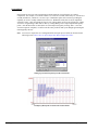
1
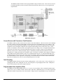
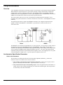
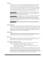
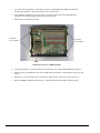
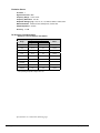
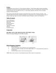
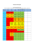
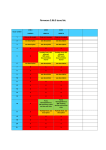
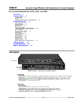
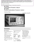
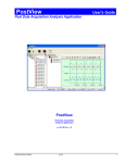
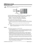
WBK18 Dynamic Signal Conditioning Module Description…… 1 Software Setup …… 7 Current Source with Transducer Fault Detection…… 2 Input Coupling …… 2 Programmable Gain Amplifier (PGA) …… 2 Low-Pass Anti-Aliasing Filter …… 3 Overrange Detection …… 3 Simultaneous Sample and Hold …… 3 TEDS Support …… 4 Excitation Source …… 4 LEDs …… 4 Hardware Setup …… 5 Configuration…… 5 Power…… 5 Assembly…… 6 Input Connections ……6 General ……7 Maximizing Alias Protection ……9 Using the 2-Pole Filter and Bypass……11 Module Configuration …… 13 Using Accelerometers …… 18 Overview …… 18 Accelerometer Specification Parameters …… 18 Electrical Grounding…… 20 Cable Driving…… 20 Fuse Replacement …… 22 Specifications …… 24 Description The WBK18 is a dynamic analog signal input module for the WaveBook data acquisition system. The WBK18 provides a complete system to interface to piezoelectric transducers that include accelerometers, microphones, force/pressure transducers, and others. WBK18, Front and Rear Panel Views Each WBK18 channel features: • • • • • • • • a 4 mA current source for transducer biasing hardware detection of a transducer fault AC (0.1 Hz or 10 Hz) or DC coupling a programmable gain amplifier (range selection) hardware overrange detection an anti-aliasing low-pass filter a simultaneous sample-and-hold (SSH) amplifier support for optional TEDS (Transducer Electronic Data Sheet), if purchased All of these parameters are independently controlled in software on a per channel basis except for overrange detection level, which is set on a per module basis. WBK18, Dynamic Signal Input Module 926896 WBK18, pg. 1 The WBK18 module includes a built-in programmable voltage excitation source. This source can be used to stimulate dynamic systems for transfer function measurements, and also serves as a test signal for the input channels. WBK18 Block Diagram Current Source with Transducer Fault Detection The WBK18 module provides constant current of 4mA to bias ICP transducers. The bias current is sourced through the center conductor of the input channel BNC connector and returns to the WBK18 by the outer conductor. The current source features an operating compliance of 24V and is short-circuit and overvoltage protected. Operating compliance refers to the highest voltage that can be applied without change of the current source value. In the absence of a transducer, the current source will output an open circuit voltage of 30V. For applications that do not require bias, the current source can be disconnected from the input via software control on a per channel basis. When the current source is enabled, the input voltage is continuously monitored with level detection circuitry. Recognition of a voltage greater than 25V (transducer open) or less than 1V (transducer short) triggers a transducer fault condition for the affected channel. This error is communicated to the user via a front panel LED and is also available through a software status request at the end of an acquisition. When recognized, an error is latched until the commencement of a new acquisition. Consequently, even intermittent faults are detected and communicated. Detection of a fault does not, however, alter the acquisition process or its data. Input Coupling Each WBK18 channel offers the selection of three coupling modes: 0.1 Hz, 10 Hz, or DC. The 0.1 Hz path is a 1pole high-pass filter with a –3dB point at 0.1 Hz. The 10 Hz path is a 2-pole high-pass filter with a –3dB point at 10 Hz. The DC path provides a direct signal connection. Programmable Gain Amplifier (PGA) The WBK18 provides programmable gains of 1, 2, 5, 10, 20, 50, 100, and 200. These correspond to bipolar input ranges of 5V, 2.5V, 1V, 500mV, 250mV, 100mV, 50mV, and 25mV. Additionally, there is a 25V DC-coupled only range that is suitable for proximity sensor measurements. Range selection is programmable on a per channel basis. WBK18, pg. 2 926896 WBK18, Dynamic Signal Input Module Low-Pass Anti-Aliasing Filter Each channel features a programmable low-pass filter to provide alias protection and to allow for the removal of undesired frequencies from the measured response. This filter is configurable within 3 modes: 8-pole, 2-pole, and Bypass. The 8-pole Butterworth switched capacitor filter offers the greatest alias protection and is most commonly used in vibration measurements. Its –3dB cutoff frequency is settable from 10 Hz to 50 kHz in a 1-2-5 progression. Application information regarding the proper setting of this filter is provided in Maximizing Alias Protection. 2-pole mode utilizes two RC filters in series. Its –3dB cutoff frequency is settable as well from 10 Hz to 50 kHz in a 1-2-5 progression. It provides tighter amplitude and offset accuracy than 8-pole mode at the expense of reduced alias protection (due to its more gradual roll-off). It is most commonly used in proximity sensor measurements, where the DC component of the input signal is critical. Additionally, the filter can be bypassed altogether, resulting in a signal bandwidth of up to 200 kHz. When the LPF (Low Pass Filter) is in the Bypass mode, the bandwidth of the system depends on the coupling mode selected. For the 0.1 Hz and 10 Hz selections, the bandwidth is approximately 190 kHz. For the DC selection, the bandwidth is approximately 130 kHz. For the 25 V range, the bandwidth is approximately 120 kHz. Reference Note: Application information regarding the 2-pole and Bypass settings of the filter is provided in the section entitled, Using the 2-Pole Filter and Bypass (page 11). Overrange Detection Each WBK18 channel is equipped with overrange detection circuitry. Use of this feature insures that all data collected during an acquisition did not exceed a user-specified level, set as a percentage of range. In its most common use, with the level set to 100%, the user is notified if the input signal exceeded the input full-scale range, even momentarily. This protection is critical, for overrange signals result in clipped data that significantly corrupts FFT analysis. This error is communicated to the user via a front panel LED and is also available through a software status request at the end of an acquisition. When recognized, an error is latched until the commencement of a new acquisition. Consequently, even intermittent faults are detected and communicated. However, an overrange event does not stop the acquisition process or change the data, providing the user with full control over the disposition of data. An extension of the overrange capability could involve its integration into a process monitor application, whereby the fault condition is used to monitor the stability of a previously characterized dynamic signal. The overrange level is programmable from 1 to 100% of range on a per WBK18 basis. Overrange detection can be enabled or disabled on a per channel basis. Simultaneous Sample and Hold All WBK18 channels are sampled simultaneously, after which the WaveBook measures each output until all channels are digitized. The time-skew between sampling on all channels is 100ns, regardless of the number of WBK18s connected to the WaveBook. This maximizes channel-to-channel phase matching. When using WaveBook with an SSH channel enabled, the per-channel sample rates are reduced. The rate reduction is the same as that which would occur if another channel were added. The per-channel rate (with SSH enabled) is: 1 MHz / (n+1), where n is the number of active channels. WBK18, Dynamic Signal Input Module 926896 WBK18, pg. 3 TEDS Support TEDS, Transducer Electronic Data Sheet, is a purchased option. The TEDS feature enables a WBK18 module to access the calibration information that is stored within TEDS-compatible sensors. The WBK18 can read calibration information from sensors and automatically scale the readings from each sensor, using the acquired calibration information. TEDS support is a software option that can easily be added after the initial purchase of the WBK18. Reference Note: Information regarding TEDS in relation to the WaveView software application begins on page 8. Excitation Source The WBK18’s AC excitation source is a sine wave-based voltage source that is programmable in frequency from 1 Hz to 5 kHz and in discrete amplitudes from 100 mVp-p to 10 Vp-p. Continuous sine, sweep sine, and custom sine modes are available. It can be used as a test source for the input channels or as excitation for other system elements, such as the amplifier for a shaker table. All of its parameters are software controlled, and its output is conveniently provided on a front panel BNC connection. Detailed information on the excitation source and its operation can be found in the Software Setup section. Do not confuse excitation source with the Source Level column in WaveView’s main window, as source level refers to transducer bias current (see Source Level, page 8) and not to the excitation source. LEDs The right-hand side of the WBK18 front panel includes 19 indicator LEDs. There are eight Transducer Fault LEDs (1 for each channel), eight Overrange LEDs (1 for each channel), an Active LED, Ready LED and a Power LED. The indicators have the following meanings. Transducer Fault (1 LED per Channel) Overrange (1 LED per Channel) When lit, a Transducer Fault LED indicates that the transducer for the associated channel has either an open circuit or a short circuit. In addition to LED indication, transducer fault information is available through a software status request at the end of an acquisition. Transducer fault errors are latched until the commencement of a new acquisition. Consequently, even intermittent faults are detected and communicated. Detection of a transducer fault does not stop an acquisition or alter data. For related information refer to Current Source with Transducer Fault Detection on page 2. When lit, an Overrange LED indicates that the associated channel’s input signal has exceeded the input full-scale range, which was programmed for that specific WBK18 module. Even a momentary exceeding of the range will cause the LED to light. This indication is critical, for overrange signals result in clipped data that significantly corrupts FFT analysis. In addition to LED indication, the overrange condition is available through a software status request at the end of an acquisition. Overrange errors are latched until the commencement of a new acquisition. Consequently, even intermittent faults are detected and communicated. Overrange events do not stop an acquisition or alter data. For related information refer to Overrange Detection on page 3. Active Lights when data is being converted. Ready Lights when the WBK18 has established communication via its Expansion Control In connector. Power Lights when power to the unit is turned on and present. WBK18, pg. 4 926896 WBK18, Dynamic Signal Input Module Hardware Setup Configuration The WBK18 requires no physical hardware settings. All WBK18 configurations are controlled by software. Reference Note: Setup information pertaining to power, expansion control, and expansion signal connections is contained in the chapter System Setup and Power Options, in the WaveBook User’s Manual. It is possible to connect a WaveBook to the host computer’s parallel port with either a 2-foot (CA-35-2) or 6-foot (CA-35-6) communication cable. To minimize the amount of noise that is introduced to the WBK18, use of the 2-foot (CA-35-2) cable with the WaveBook is recommended. Power The WBK18 module can be powered by an AC power adapter or directly from any 10 to 30 VDC source, such as a 12 V car battery. For portable or field applications, the WBK18 and the WaveBook can be powered by the DBK30A rechargeable battery module. Reference Note: For details regarding power, refer to the chapter, System Setup and Power Options, in the WaveBook User’s Manual. As described in this referenced chapter, it is possible to power the WBK18 from the POWER OUT DIN5 connector on the WaveBook and to power other WBK expansion modules from the POWER OUT DIN5 connector on the WBK18. The following notes apply to those types of power connections. Tables for determining amp load are provided in the WaveBook User’s Manual chapter entitled System Setup and Power Options. The following factors are very important. • Calculate system amp load prior to creating a system daisy-chain. Although WaveBook device connectors and CA-115 power cables have 5 amp limits, TR-40Us are limited to 2.2 amps. If necessary use auxiliary or high-current power supplies. • If using an AC power adapter for the system power, use separate adapters for the WaveBook and the WBK18. • The WBK18 has a 5 amp current limit. TR-40U power supplies are limited to 2.2 amps. Power consumption calculations must be done to ensure that a particular daisy-chain scheme does not exceed either of these current limits. WBK18, Dynamic Signal Input Module 926896 WBK18, pg. 5 To ensure that the software recognizes all system components, when powering up an Ethernet connected WaveBook system, it is important that the WaveBook/516E (or WBK25) is powered last, and that the most remote system components are powered first. Other power-up sequences will result in software’s failure to recognize all components.* • First, power-on the WBK expansion modules. • Second, power-on WaveBooks or WBK modules that are connected to the expansion ports of the WaveBook/516E or WBK25. • Finally, power-on the WaveBook/516E and/or WBK25 devices. *An exception to this power-up scheme is to power-on the entire system at once. Assembly The WBK18 has the same footprint as the WaveBook and other modules, allowing for convenient mounting. A fastener panel allows multiple units to be stacked vertically. Screw-on handles are available for portable applications. For more assembly information, see chapter 3 of the WaveBook User’s Manual (p/n 489-0901). Input Connections All input connections are made into the front panel BNCs, in which the BNC center conductor is the signal HI and the BNC shell is the signal LO. The BNC shell is common among all eight input channels and is not isolated from earth ground. Consequently, the shell is not meant to be driven with respect to earth ground. An additional consideration exists regarding the setup of the input transducer. If the transducer case is effectively earth grounded through its connection to a device under test, there exists the possibility for added measurement noise due to the ground loop that is created. This issue is minimized by electrically isolating the transducer from the device. CAUTION The BNC shell is not to be driven with respect to earth ground. Attempting to do so could result in equipment damage. Additional measurement noise may be present when using earth grounded transducers. For best results, electrically isolate the input transducers from earth ground. WBK18, pg. 6 926896 WBK18, Dynamic Signal Input Module Software Setup General Depending on your application, you will need to set several software parameters. Proper settings will allow WaveView to organize data to meet your requirements. Some items of importance to the WBK18 are the low-pass and high-pass filter options that can be selected from the WaveView Configuration main window and the excitation source and overrange detection parameters that can be chosen from the Module Configuration window. The Module Configuration window can be accessed from the View pulldown menu or by use of the first toolbar button (located just below the File pull-down menu). Reference Note: For detailed WaveView information, refer to the WaveView Document Module. WaveView Configuration Window In the WaveView Configuration main window (see figure) the following columns are applicable to the WBK18. LPF Mode – Click on a cell in the LPF Mode column to make the cell active, and then change its setting. Options for WBK18’s LPF Mode are: (a) 8-Pole: selects the 8-pole low-pass filter (b) 2-Pole: selects the 2-pole low-pass filter (c) Bypass – bypasses the low-pass filter LPF Cutoff - Click on a cell in the LPF Cutoff column to make the cell active, and then change its setting. Options for LPF Cutoff (in Hz) are: 10, 20, 50, 100, 200, 500, 1000, 2000, 5000, 10000, 20000, and 50000. Note that when the LPF Mode is “Bypass,” this parameter is fixed at 200000 Hz. Reference Note: Application information regarding the proper setting of LPF Mode and LPF Cutoff is provided in the sections entitled Maximizing Alias Protection (page 9) and Using the 2-Pole Filter and Bypass (page 11). HPF Cutoff - This is used to select input coupling. Click on a cell in the HPF Cutoff column to make the cell active, and then change its setting. Options for HPF Cutoff are: (a) 0.1 Hz: selects the 0.1 Hz, 1-pole high-pass filter (b) 10 Hz: selects the 10 Hz, 2-pole high-pass filter (c) DC: selects DC coupling Note that when the Range is “±25V,” the HPF Cutoff is fixed at DC. Range - This is used to select the input range. Click on a cell in the Range column to make the cell active, and then change its setting. Options for Range are: ±25V, ±5V, ±2.5V, ±1V, ±500mV, ±250mV, ±100mV, ±50mV, and ±25mV. Note that when the Range is “±25V,” the HPF Cutoff is fixed at DC. WBK18, Dynamic Signal Input Module 926896 WBK18, pg. 7 Source Level – Source Level refers to the transducer bias current and is not to be confused with the excitation source that is discussed on pages 4 and 14. The current Source Level column of WaveView’s main window is used to turn the transducer bias current on at a current value of 4 mA, or to turn the transducer bias current off. Click on a cell in the Source Level column to make the cell active, and then change its setting to 4 mA or to off, according to the application. If a channel is connected to a transducer that requires a current source, set the source level to 4 mA; otherwise set the source level to off. TEDS (Transducer Electronic Data Sheet) TEDS is a purchased option that enables WBK18 modules to access calibration information from TEDS-compatible sensors. The WBK18 automatically scales the readings and sets the range according to the information stored on the sensor. This is done independently for each TEDS associated channel, providing that “Yes” appears in the TEDS Data cell (right-hand column, following figure). WaveView Configuration Window If no WBK18 channels are connected to a TEDS sensor, the entire TEDS Data column, including the heading, will be grayed-out. When a channel does have a TEDS sensor it will have an associated cell. You can click on the cell to access the “Use TEDS Data” pull-down list, which offers 3 choices: No, Yes, and Show. • “No” instructs WaveView not to use TEDS. When TEDS is not used the associated channel will use the default range and units of volts (V). • “Yes” instructs WaveView to use TEDS. The channel’s ranges will be automatically scaled according to the TEDS sensor’s calibration data and the units will appear as “g.” • “Show” accesses an Accelerometer TEDS Information box for the associated channel. An example is provided to the right. The channel, in this case channel 9, is identified in the title bar. When the information box is closed the TEDS Data cell will indicate its previous status of Yes or No. Accelerometer TEDS Information Box If you add, remove, or relocate a TEDS sensor at the WBK18 channel inputs, the TEDS information, and WaveView’s range and units will not reflect the change until either (a) the WaveBook is reselected as a device, or (b) WaveView is closed and then reopened. WBK18, pg. 8 926896 WBK18, Dynamic Signal Input Module Maximizing Alias Protection What is Aliasing? Aliasing is a phenomenon of sampled data systems wherein a high frequency signal is misrepresented as a low frequency signal when the A/D converter sampling rate being used is too slow. This misrepresentation can result in severe data corruption and incorrect FFT results. Aliasing is a well-documented data acquisition effect, and interested users are encouraged to research detailed information that is available online from companies such as Analog Devices and Texas Instruments. This text aims to not supplant those resources, but to provide most users with sufficient knowledge to avoid most alias problems through proper filter and sampling rate configuration. For a given sampling rate, FS, input signals of frequency up to FS/2 will be processed correctly. However, input signals above FS/2 are subject to aliasing. For example, a sampling rate of 100 kHz can process signals up to 50 kHz without aliasing. An input signal of 90 kHz, however, will be aliased. Specifically, it will appear in the sampled data as a signal of frequency FS-FIN, which in this case is 100 kHz-90 kHz = 10 kHz. Aliasing, and its prevention, should be a consideration in all sampled data systems. This is especially important in mechanical vibration measurements, because most mechanical systems exhibit a resonance apart from their fundamental frequency. That is, there may be signal energy present that has the potential to be aliased that is unknown to the user. And the worst part of aliasing is that its effects are indistinguishable from real input signals. That is, in the given example, it is not apparent to the user whether the 10 kHz energy is real or an alias. Aliasing Protection using the WBK18 The WBK18 provides alias rejection via its 8-pole filter. This filter has an extremely steep roll-off characteristic, very closely achieving an ideal “brickwall” response. It consequently passes frequencies of interest without significant attenuation, but significantly attenuates frequencies just above. Its attenuation is so high that most alias frequency energy is reduced to a level below the noise floor of the measurement system. However, it must be configured correctly to achieve these results. In general, the cutoff frequency (FC) of the filter should be set as close to, but above, the highest input frequency of interest. This will maximize the alias rejection it provides. The 8-pole filter provides excellent filter response. However, no filter is perfect, meaning that some signal attenuation occurs for frequencies just below FC and maximum attenuation is not exhibited for frequencies just above FC. For reference, the typical response of the 8-pole filter is provided in the table at the right and the graphs that follow. WBK18, Dynamic Signal Input Module 926896 FIN/FC <0.1 0.1 0.2 0.3 Gain (dB) -0.15 -0.15 -0.18 -0.22 0.4 0.5 0.6 0.7 0.8 0.9 1.0 1.25 1.5 1.75 2.0 2.5 2.8 3.0 3.3 3.5 4.0 -0.27 -0.33 -0.39 -0.47 -0.68 -1.4 -3.6 -16 -28 -39 -48 -63 -70 -75 -80 -86 -95 WBK18, pg. 9 Gain of 8-pole Filter Mode 0 0.5 1 1.5 2 2.5 3 3.5 4 0 Gain (dB) -20 -40 -60 -80 -100 FIN/FC Gain of 8-pole Filter Mode 0 0.2 0.4 0.6 0.8 1 0 Gain (dB) -2 -4 -6 -8 -10 -12 -14 FIN/FCFrequency Region FIN/FC, Zoom-In to Filter Cutoff As described above, aliasing results from the relationship between input frequency and sampling frequency. Configuring the filter correctly serves to attenuate undesired frequencies. However, thought must also be given to the sampling rate of the A/D converter. In general, for alias considerations, the sampling rate should be set as high as possible, given the number of active channels being used. Recall that the maximum sampling rate is 1 MHz/(n +1) where n is the number of active channels. Because the sampling rate determines the frequency at which aliasing occurs, it determines the input signal bandwidth, for a given level of alias rejection. This relationship is shown in the following example. Example # of channels: 4 Alias rejection: -70dB min The sampling rate (FS) is chosen to be the maximum of 1 MHz/(4 +1) = 200 kHz. The alias frequency is FS/2, or 100 kHz. Referring to the attenuation table, to achieve a minimum of –70dB of alias rejection, there must be at least a 2.8 ratio between FIN and FC. For the FIN value of 100 kHz, this translates into a maximum value of FC of 100 kHz / 2.8 = 35.7 kHz. The largest available FC value that satisfies this condition is 20 kHz. The input signal bandwidth for this case is then 20 kHz. WBK18, pg. 10 926896 WBK18, Dynamic Signal Input Module 1.2 Using the 2-pole Filter and Bypass 2-pole Filter Mode For applications where the signal of interest is entirely AC in nature, the low-pass filter mode of 8-pole is the best choice. Vibration signals coupled through an ICP accelerometer are an example of this. However, for applications where the DC component of the input signal is also of importance, 2-pole mode may provide better results. Proximity sensor measurements are an example of this. This is because the 8-pole switched capacitor filter, while providing excellent attenuation characteristics, does not process DC signals with a high level of accuracy. For accelerometer applications this is not a limitation, as there is no information in the DC component of the input signal. The 2-pole filter, in contrast, is formed by two 1pole RC filters in series. This filter provides excellent passband accuracy, at the expense of a more gradual roll-off characteristic, as detailed below. Gain of 2-pole Filter Mode 0 10 20 30 40 50 60 70 80 90 100 0 -10 Gain (dB) -20 -30 -40 -50 -60 -70 -80 FIN/FC Gain of 2-pole Filter Mode 0 0.5 1 1.5 2 2.5 3 3.5 4 4.5 5 0 Gain (dB) -5 -10 -15 -20 -25 FIN/FC, Zoom-In to Filter Cutoff Frequency Region WBK18, Dynamic Signal Input Module 926896 WBK18, pg. 11 Bypass Mode Bypass mode also provides excellent passband accuracy and provides minimal signal attenuation up to very high frequencies for those applications that need to measure signals of frequency exceeding 20 kHz. For reference, the typical roll-off characteristic of Bypass mode is the following: Gain of Bypass Mode Gain (dB) 0 25 50 75 100 125 150 175 200 225 250 35 40 45 50 0 -0.5 -1 -1.5 -2 -2.5 -3 -3.5 -4 -4.5 FIN (kHz) Gain of Bypass Mode 0 5 10 15 20 25 30 0 Gain (dB) -0.05 -0.1 -0.15 -0.2 -0.25 -0.3 FIN (kHz), Zoom-In to Filter Cutoff Frequency Region WBK18, pg. 12 926896 WBK18, Dynamic Signal Input Module DC Accuracy As previously mentioned, the 2-pole and Bypass filter modes are most commonly used in applications where DC signal information is important. The AC response of each of these modes is described above. The DC accuracy, excluding noise, for both modes is: Accuracy at 0° to 50°C (32° to 122°F) Range ± % of Reading Typical Maximum Offset ±25V 0.5 1 ±15mV ±5V 0.15 0.3 ±3mV ±2.5V 0.15 0.3 ±2mV ±1V 0.15 0.3 ±1mV ±500mV 0.15 0.3 ±900µV ±250mV 0.15 0.3 ±800µV ±100mV 0.15 0.3 ±800µV ±50mV 0.15 0.3 ±800µV ±25mV 0.2 0.4 ±800µV These numbers are valid for 1 year after calibration and over the entire operating temperature range of the unit. Module Configuration Overrange Detection The configuration of overrange detection is done through the Module Configuration window. The Module Configuration window can be accessed from the View pull-down menu or by use of the first toolbar button (located just below the File pulldown menu). In this window, the user enables/disables overrange detection on a per channel basis. A checkmark next to the channel number indicates that overrange detection is enabled for that channel. The overrange detection level is also set in this screen. It is set as a percentage of range that applies to all channels of the WBK18 unit being configured. After channel enable and level selections are made, the “Apply” button must be clicked to accept the changes. Module Configuration Window When configuring overrange detection, after channel enable and level selections are made, the <Apply> button must be clicked to accept the changes. WBK18, Dynamic Signal Input Module 926896 WBK18, pg. 13 Excitation Source In order to configure the excitation source, click on the Configure Sine Wave Output button in the Module Configuration window. This brings up a secondary window in which the excitation source is configured. Do not confuse excitation source with the Source Level column in WaveView’s main window. Continuous Mode Continuous mode refers to a continuously running sine wave of the selected amplitude and frequency. To configure, select a frequency and amplitude, and then click “Start.” The selected output will begin and continue running until the <Stop> button is clicked or WaveView is terminated. Note: You can save output sine wave configuration files and open pre-saved files as discussed in the upcoming section, How to Save or Open Output Sine Wave Configuration Files, page 17. Continuous Tab Selected Sweep Mode Sweep mode refers to a constant amplitude sine wave that is being swept in frequency from a selected start frequency to a selected stop frequency over a selected sweep time duration. The frequency sweep characteristic can be chosen to be linear or logarithmic, and is distributed among 1280 discrete steps. The transitions between steps are continuous in phase and in amplitude. To configure, make selections for the available parameters, and then click the <Start> button. Once a sweep is completed, the waveform returns to its start frequency and is swept again and again until stopped by the user or WaveView is terminated. Note: You can save output sine wave configuration files and open pre-saved files as discussed in the upcoming section, How to Save or Open Output Sine Wave Configuration Files, page 17. Sweep Tab Selected WBK18, pg. 14 926896 WBK18, Dynamic Signal Input Module Sweep Mode (continued) Example of a Linear Sweep Waveform Example of a Log Sweep Waveform WBK18, Dynamic Signal Input Module 926896 WBK18, pg. 15 Custom Mode In this mode, the user can create customized waveforms built out of specified sine wave-based components. For example, a waveform could be 1V, 1 kHz for 2 seconds, followed by 5V, 100 Hz for 5 seconds, and then 2V, 500 Hz for 1 second. Up to 1280 distinct points can be entered, providing the capability to create a virtually unlimited waveform set. Within this mode, there is also an amplitude selection of 0 mV. This corresponds to an active zero voltage and is used to create off time in a voltage waveform. Programming of this mode is done by creating/editing a list of output amplitude/frequency points. After the desired list is entered, the waveform output is begun by clicking “Start.” Once the waveform sequence completes, it returns to the first entry in the list and cycles through again and again until stopped by the user. Note: You can save output sine wave configuration files and open pre-saved files as discussed in the following section, How to Save or Open Output Sine Wave Configuration Files. Setting Up Custom Waveforms from the Custom Tab Example of Waveforms Created in the Custom Mode WBK18, pg. 16 926896 WBK18, Dynamic Signal Input Module How to Save or Open Output Sine Wave Configuration Files Within all modes, there is the ability to save and recall waveform configurations, which is very beneficial for complex custom configurations. Within WaveView, this feature is accessed through File in the WBK18 Output Sine Wave Configuration Window. To Save a Configuration 1. Click on “File” in the upper left corner of the screen. 2. Click on the option labeled “Save Waveform Configuration As…” 3. Name the file. Note that it will have a .dds extension. 4. Save the file to the desired drive. To Open a Configuration 1. Click on “File” in the upper left corner of the screen. 2. Click on the option labeled “Open Waveform Configuration…” 3. Open the desired file. WBK18, Dynamic Signal Input Module 926896 WBK18, pg. 17 Using Accelerometers Overview A low-impedance piezoelectric accelerometer consists of a piezoelectric crystal and an electronic amplifier. When stretched or compressed, the two crystal surfaces develop a charge variation that is related to the amount of stress, shock, or vibration on the crystal. The amplifier outputs a corresponding signal and transforms the sensor’s high impedance to a lower output impedance of a few hundred ohms. Note that, in addition to acceleration, these sensors can also measure pressure and force. The circuit requires only two wires (coax or twisted pair) to transmit both power and signal. At low impedance, the system is insensitive to external or “triboelectric” cable noise. Cable length does not affect sensitivity. The following figure shows a simple sensor-WBK18 connection. The voltage developed across R is applied to the gate of the MOSFET. The MOSFET is powered from a constant current source of 4 mA and 30 volts. The MOSFET circuit will bias at approximately 12 V in the quiet state. As the system is excited, voltage is developed across the crystal and applied to the gate of the MOSFET. This voltage will cause linear variation in the impedance of the MOSFET and a proportional change in bias voltage. This voltage change will be coupled to the WBK18 input amplifier through the capacitor C. The value of R and the internal capacitance of the piezoelectric crystal control the low frequency corner. Units weighing only a few grams can provide high-level outputs up to 1 V/g with response to frequencies below 1 Hz. Accelerometer Specification Parameters Noise in Accelerometers The noise floor or resolution specifies the lowest discernible amplitude (minimum “g”) that can be measured. There are two main sources of noise as follows: • Noise from the crystal and microcircuit inside the accelerometer. Some types of crystals, such as quartz, are inherently noisier than others. A good noise floor is 10 to 20 µV. • Noise from electrical activity on the mounting surface. Since the signal from the accelerometer is a voltage, 60 Hz or other voltages (ground loop, etc) can interfere with the signal. The best protection is to electrically isolate the accelerometer. WBK18, pg. 18 926896 WBK18, Dynamic Signal Input Module Sensitivity The sensitivity of an accelerometer is defined as its output voltage per unit input of motion. The unit of motion used is “g.” One “g” is equal to the gravitational acceleration at the Earth’s surface, which is 32.2 ft/(sec)(sec) or 981 cm/(sec)(sec). The output is usually specified in millivolts per “g” (mV/g). Sensitivity is usually specified under defined conditions such as frequency, testing levels, and temperature. An example: 100 mV/g at a frequency of 100 Hz, level +1 g, at 72°F. Note that, although a sensor may have a “typical” sensitivity of 100 mV/g, its actual sensitivity could range from 95 to 105 mV/g (when checked under stated conditions). Manufacturers usually provide sensor calibration values. Transverse Sensitivity - An accelerometer is designed to have one major axis of sensitivity, usually perpendicular to the base and co-linear with its major cylindrical axis. The output caused by the motion perpendicular to the sensing axis is called transverse sensitivity. This value varies with angle and frequency and typically is less than 5% of the basic sensitivity. Base-Strain Sensitivity - An accelerometer’s base-strain sensitivity is the output caused by a deformation of the base, due to bending in the mounting structure. In measurements on large structures with low natural frequencies, significant bending may occur. Units with low base-strain sensitivity should be selected. Inserting a washer (smaller in diameter than the accelerometer base) under the base reduces contact surface area; and can substantially reduce the effects of base-strain. Note that this technique lowers the usable upper frequency range. Acoustic Sensitivity - High-level acoustic noise can induce outputs unrelated to vibration input. In general, the effect diminishes as the accelerometer mass increases. Use of a light, foam-rubber boot may reduce this effect. Frequency Response An accelerometer’s frequency response is the ratio of the sensitivity measured at frequency (f) to the basic sensitivity measured at 100 Hz. This response is usually obtained at a constant acceleration level, typically 1 g or 10 g. Convention defines the usable range of an accelerometer as the frequency band in which the sensitivity remains within 5% of the basic sensitivity. Measurements can be made outside these limits if corrections are applied. Care should be taken at higher frequencies because mounting conditions greatly affect the frequency range (see Mounting Effects, in upcoming text). Dynamic Range The dynamic measurement range is the ratio of the maximum signal (for a given distortion level) to the minimum detectable signal (for a given signal-to-noise ratio). The dynamic range is determined by several factors such as sensitivity, bias voltage level, power supply voltage, and noise floor. Bias Level Under normal operation, a bias voltage appears from the output signal lead to ground. There are two basic MOSFET configurations commonly used. One exhibits a 7-8 V bias and the second a 9-12 V bias. Operation of the two circuits is identical except for the available signal swing. Thermal Shock - Temperature Transients Piezoelectric accelerometers exhibit a transient output that is a function of a temperature’s “rate-ofchange.” This “thermal shock” is usually expressed in g/°C and is related to: • Non-uniform mechanical stresses set up in the accelerometer structure. • A pyroelectric effect in piezoelectric materials—an electrical charge is produced by the temperature gradient across the crystal. This quasi-static effect produces a low-frequency voltage input to the MOSFET amplifier. This voltage is usually well below the low-frequency corner, but the effect can reduce the peak clipping level and cause loss of data. This effect does not affect the accelerometer’s basic sensitivity or the data unless the thermal shift in the operation bias level results in clipping. Where drastic thermal shifts are expected, use 12 V bias models. The effect’s severity is related to the mass of the accelerometer. In 100 mV/g industrial units, the effect is usually negligible. Using rubber thermal boots can reduce the effect significantly. WBK18, Dynamic Signal Input Module 926896 WBK18, pg. 19 Overload Recovery Recovery time from clipping due to over-ranging is typically less than 1 ms. Recoveries from quasi-static overloads that generate high DC bias shifts are controlled by the accelerometer input RC time constant that is fixed during manufacture. Connector This parameter specifies the connector type and size (4-48, 6-40, 10-32 coaxial etc) and the location on the sensor, that is, top or side (usually on the hex base). Where there is no connector on the sensor, an integral cable is specified with the length and the connector, that is, integral 6-ft to 10-32. Electrical Grounding Case-Grounded Design In case-grounded designs, the common lead on the internal impedance matching electronics is tied to the accelerometer case. The accelerometer base/stud assembly forms the signal common and electrically connects to the shell of the output connector. Case-grounded accelerometers are connected electrically to any conductive surface on which they are mounted. When these units are used, take care to avoid errors due to ground noise. Isolated-Base Design To prevent ground noise error many accelerometers have base-isolated design. The outer case/base of the accelerometer is isolated electrically off ground by means of an isolation stud insert. The proprietary material used to form the isolation provides strength and stiffness to preserve high-frequency performance. Cable Driving Operation over long cables is a concern with all types of sensors. Concerns involve cost, frequency response, noise, ground loops, and distortion caused by insufficient current available to drive the cable capacitance. The cost of long cables can be reduced by coupling a short (1 m) adapter cable from the accelerometer to a long low-cost cable like RG-58U or RG-62U with BNC connectors. Since cable failure tends to occur at the accelerometer connection where the vibration is the greatest, only the short adapter cable would need replacement. Capacitive loading in long cables acts like a low-pass, second-order filter and can attenuate or amplify high-frequency signals depending on the output impedance of the accelerometer electronics. Generally this is not a problem with low-frequency vibration (10 Hz to 2000 Hz). For measurements above 2000 Hz and cables longer than 100 ft, the possibility of high-frequency amplification or attenuation should be considered. The maximum frequency that can be transmitted over a given length of cable is a function of both the cable capacitance and the ratio of the maximum peak signal voltage to the current available from the constant current source: f = WBK18, pg. 20 K V 2πC Icc − Ib Drive Current Cable Length (mA) @30 pF/ft (Ft) Frequency Response to 5% of Maximum Output Signal Amplitude ±1V ±5V 4 10 550 kHz 110 kHz 4 100 55 kHz 11 kHz 4 1000 5.5 kHz 1.1 kHz Where: f = Maximum frequency in Hz 9 K = 3.45 ×10 . K is the scale factor to convert Farads to picoFarads and Amperes to milliAmperes and a factor to allow cable capacitance to charge to 95% of the final charge. C = Cable capacitance in picoFarads V = Maximum peak measured voltage from sensor in volts Icc = Constant current from current source in mA Ib = Current required to bias the internal electronics, typically 1 mA 926896 WBK18, Dynamic Signal Input Module Fuse Replacement – for WBK18 CAUTION Turn OFF the power to, and UNPLUG the WBK18 module and all connected equipment. Remove all signal I/O lines from the unit. Electric shock or damage to equipment can result even under low-voltage conditions. Take ESD precautions, to include using a grounded wrist strap. Use care to avoid touching board surfaces and onboard components. Ensure boards do not come into contact with foreign elements such as oils, water, and industrial particulate. You should only replace a fuse if your device shows no sign of damage. If your device appears damaged such as evidenced by a “smoked” component, contact the factory as soon as possible. If the replacement fuse blows, contact the factory as this indicates a problem may exist with your WBK18 module. Each WBK18 has one user-replaceable fuse designated as F900. F900 Input Power Fuse. 4.0 A, MINI ATO. This 4-amp fuse is located near the rear panel’s 5DIN POWER IN connector. If this fuse has blown the WBK18 module will not power up. Factory Part Number: FU-8-4 Littelfuse Part Number: 297-004, Littelfuse Body Color Code: Pink You will need the following: • • • • Phillips Screwdriver 3AG Fuse Puller, or needle-nose pliers* Grounding wrist strap and associated anti-static pad Replacement fuse F900 * Needle-nose pliers can be used to pull MINI ATO fuses; but should not be used to insert fuses. WBK18, Dynamic Signal Input Module 926896 WBK18, pg. 21 1. If you have not already done so, turn OFF the power to, and UNPLUG the WBK18 module and all connected equipment. Remove all signal I/O lines from the unit. 2. Using a Phillips screwdriver, remove the four Cover Plate Screws from the left and right sides of the unit. The following figure points out the screw locations. 3. Remove the Cover Plate [not shown]. Cover Plate Screw Locations Cover Plate Screw Locations F900 F900 Fuse Location in a WBK18 Module 4. Locate the F900 fuse. It is located near the rear panel edge, close to the DIN5 POWER IN connector. 5. While wearing a grounded wrist strap, remove and replace the bad fuse. Ensure that the new fuse is fully seated. 6. Replace the Cover Plate and secure it to the chassis with the 4 screws that were removed in step 2. 7. Return the WBK18 module to normal service. Should any problems be noted, consult the factory. WBK18, pg. 22 926896 WBK18, Dynamic Signal Input Module Specifications – WBK18 Specifications are subject to change without notice. General System Connectors: BNC connector, mates with expansion signal input on the WaveBook; female DB15 connector, mates with expansion control signal on the WaveBook. Input Power Range: 10 to 30 VDC Input Power Fuse F900: 4A MINI ATO, user replaceable; refer to page 21 for details. Power Consumption @ 12V: 1.6A @ 15V: 1.3A @ 24V: 0.8A Environment Operating: 0° to 50°C; 0 to 95% RH, non-condensing Storage: 0° to 70°C Vibration: MIL STD 810E, category 1 Dimensions: 280 mm W x 216 mm D x 42 mm H (11” x 8.5” x 1.65”) Weight: 1.3 kg (2.9 lbs) Analog Inputs Channels: 8 Signal Connection: 1 BNC per channel Input Impedance: 200k Ohm (single-ended) Input Coupling: AC, DC (software programmable per channel) High-Pass Filter: 0.1 Hz or 10 Hz (software programmable per channel) Input Ranges: ±25V (DC coupled only), ±5V, ±2.5V, ±1V, ±500mV, ±250mV, ±100mV, ±50mV, ±25mV (software programmable per channel) Overrange Detection: Programmable from 1% to 100% of range Overrange Indication: Front panel LED per channel, software status Low-Pass Filter (software programmable per channel) Type: 8-pole Butterworth with simultaneous sample-and-hold (SSH) Cutoff Frequency (Fc): 10 Hz to 50 kHz in 1-2-5 progression Alias Rejection: 75dB min Channel-to-Channel Phase Matching*: 1° typ, 2° max Unit-to-Unit Phase Matching*: 1° typ, 2° max SSH latency: 100ns max Amplitude Accuracy**: ±0.5dB (Fin ≤ Fc/2) Total Harmonic Distortion: -70dB typ ICP Bias Source: 4mA, 24V compliance (on/off software programmable per channel) ICP Fault Detection Thresholds: <1V (short), >25V (open) ICP Fault Indication: Front panel LED per channel, software status * Conditions for Low-Pass Filter Phase-Matching 8-pole LPF mode, 0.1 Hz or DC HPF mode 1 Hz ≤ Fin ≤ Fc/2 200 Hz ≤ Fc ≤ 20 kHz All WBK18 units connected to same WaveBook ** Condition for Amplitude Accuracy For Fin < 20 kHz WBK18, Dynamic Signal Input Module 926896 WBK18, pg. 23 Excitation Source Channels: 1 Signal Connection: BNC Frequency Range: 1 Hz to 5 kHz Frequency Resolution: 0.01 Hz Amplitude Settings (p-p): 10V, 5V, 2V, 1V, 500mV, 200mV, 100mV, 0mV Waveform Modes: Continuous sine, Sweep sine, Custom sine Output Impedance: 50 Ohm Accuracy: ±0.1dB DC Accuracy, Excluding Noise Applies to 2-Pole and Bypass Filter Modes Accuracy at 0° to 50°C (32° to 122°F) Range ± % of Reading Typical Maximum Offset ±25V 0.5 1 ±15mV ±5V 0.15 0.3 ±3mV ±2.5V 0.15 0.3 ±2mV ±1V 0.15 0.3 ±1mV ±500mV 0.15 0.3 ±1mV ±250mV 0.15 0.3 ±1mV ±100mV 0.15 0.4 ±1mV ±50mV 0.15 0.4 ±1mV ±25mV 0.2 0.4 ±1mV These numbers are valid for 1 year after calibration and over the entire operating temperature range of the unit. Specifications are continued on following page. WBK18, pg. 24 926896 WBK18, Dynamic Signal Input Module Typical Performance Characteristics WBK18 Frequency Spectrums (typical) Each spectrum was taken from a WaveBook/516A that was sampling at 20kSamples/sec, 4096-point FFT, B-H Window. 3 Vpp, 1000Hz Sine wave input; ±5V range, 10Hz High pass filter, 10 kHz 8-pole Low pass filter. 8 Vpp, 1000Hz Sine wave input; ±5V range, 10Hz High pass filter, 10 kHz 2-pole Low pass filter. 8 Vpp, 1000Hz Sine wave input; ±5V range, 10Hz High pass filter, 200 kHz Low pass filter (Bypass mode). WBK18, Dynamic Signal Input Module 926896 WBK18, pg. 25 WBK18, pg. 26 926896 WBK18, Dynamic Signal Input Module