1
Embedded Now ComExpress Carrier Hardware User Manual
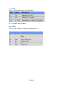
7. LEDs
There are LEDs on the board as described below;
LED
Signal
Description
D2
5V
On when 5V is valid
D3
3.3V
On when 3.3V is valid
D12
V_LCD
On when the 5V to the LVDS is enabled
8. Switches and Shunts
8.1. Shunts
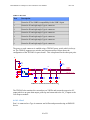
There are four shunts on the board. They are defined below.
!
Shunt
State
Description
J10
In
Allows software control of the V_LCD
Enable
J10
Out
V_LCD is forced on
J11
In
V_LCD = 3.3V
J11
Out
V_LCD = 5V
!
! of 21
21
!
Rev 0.20